JP3660955B2 - Heat exchange ventilator - Google Patents
Heat exchange ventilator Download PDFInfo
- Publication number
- JP3660955B2 JP3660955B2 JP00958096A JP958096A JP3660955B2 JP 3660955 B2 JP3660955 B2 JP 3660955B2 JP 00958096 A JP00958096 A JP 00958096A JP 958096 A JP958096 A JP 958096A JP 3660955 B2 JP3660955 B2 JP 3660955B2
- Authority
- JP
- Japan
- Prior art keywords
- motor
- impeller
- casing
- air
- chamber
- Prior art date
- Legal status (The legal status is an assumption and is not a legal conclusion. Google has not performed a legal analysis and makes no representation as to the accuracy of the status listed.)
- Expired - Fee Related
Links
Images


Description
【0001】
【発明の属する技術分野】
屋外からの給気と室内からの排気との間で熱交換させつつ換気する天井埋込形の熱交換換気装置に関する。
【0002】
【従来の技術】
上記の熱交換換気装置では、この熱交換エレメントで交差する給気及び排気の流れは、それぞれシロッコファンやターボファン等の遠心ファンによって生成されている。この種のファンは、遠心式の羽根車と、この羽根車を収容したファンケーシングにより構成されている。
【0003】
また、通常、この種のファンでは、羽根車を収容した羽根車室と、羽根車を駆動するためのモータを収容したモータ室とが、独立して構成されているが、このモータ室内にモータが発生する熱が滞留するのを防止することが要望されていた。
従来、排気のみを目的とする換気扇において、遠心ファンとして、両吸込形の羽根を用い、モータ室側とこれの反対側の双方から室内空気を吸い込むようにしたものが提供されている(実公平6−3321号公報参照)。
【0004】
【発明が解決しようとする課題】
しかしながら、上記公報のものでは、両吸込形の羽根を使用しなければならず、製造コストが高くなる。
ところで、風量が少なくても空気が流れておれば、モータの冷却には十分である一方、モータに風を当て過ぎると、モータの駆動軸やこれを支持する軸受に多くの塵埃が付着し、軸受の寿命を低下させる傾向にある。
【0005】
これに対して、上記の両吸込形の羽根車では、一般に、両側からの吸い込み風量に差を持たせ難いので、モータを通過する風量をあまり小さく設定することができない。したがって、モータの駆動軸等に塵埃等が付着し易い。
そこで、本発明の目的は、製造コストが安く且つモータの駆動軸等への塵埃等の付着を抑制することができる熱交換換気装置を提供することである。
【課題を解決するための手段】
上記目的を達成するため、
1)請求項1記載の発明は、
箱型の本体ケーシング内に、熱交換エレメント及びこの熱交換エレメントで交差する給気と排気の流れをそれぞれ生成する一対のファンを収容した熱交換換気装置において、
少なくとも一のファンは、モータと同軸に連結され且つモータと反対側から空気を吸い込む片吸込形の羽根車と、この羽根車を収容した羽根車室を区画形成したファンケーシングとで構成され、上記ファンケーシングによって、上記モータを収容したモータ室の少なくとも一部が区画され、上記羽根車室は、収容した羽根車の吸込側に対応して吸込口を形成しており、この吸込口へは、モータ室を経由する風路およびモータ室を経由しない風路を介して空気が吸い込まれ、上記ファンケーシング (18) は上下に二分割された第1および第2の分割体 (19,20) からなり、各分割体 (19,20) の3つの側面が本体ケーシング (1) の対応する3つの側板 (11 〜 13) にそれぞれ当接して位置決めされることを特徴とする。
【0006】
上記構成では、モータ室を経由する風路とモータ室を経由しない風路とが、ともに羽根車の同側に導かれるように風路構成し、これに応じて安価な片吸込形の羽根車を用いた。また、羽根車を片吸込形としたので、モータ室を経由する風路の風量とモータ室を経由しない風路の風量の比を所望に設定でき、ひいては、モータ室を経由する風路の風量を、モータの冷却が可能な必要最小限の風量に設定できる結果、モータの駆動軸への塵埃の付着を抑制できる。
【0007】
また、ファンケーシングによってモータ室の一部が区画されるので、これを区画するために別部材を設ける場合と比較して、部品コスト及び組立コストを削減できる結果、製造コストを安価にすることができる。
2)請求項2記載の発明は、
請求項1記載の熱交換換気装置において、上記モータ室を経由する風路は、モータ室と上記羽根車室の吸込口を連通する連通空間を含み、この連通空間は、上記ファンケーシングの上部に形成された凹部と本体ケーシングの天板との間に形成されていることを特徴とする。
【0008】
上記構成では、本体ケーシングにファンケーシングを組み込むだけで、これら両者の間に、第1の排気風路に含まれる連通空間を形成できるので、上記両者と別の部材を用いて連通空間を形成する場合と比較して、部品コスト及び組立コストの低減を通じて製造コストを安価にすることができる。
【0010】
【発明の実施の形態】
図1は本発明の一実施形態に係る熱交換換気装置の概略構成を示す分解斜視図であり、図2はメンテナンス時において本装置を下方から見た一部破断斜視図であり、図3は本装置の組み立て工程を説明するための部分断面分解側面図である。
【0011】
図1を参照して、本熱交換換気装置A(以下、単に換気装置Aという)は、屋外からの給気S(図中、実線矢印で示す)と室内からの排気E(図中では、経路毎にハッチング付矢符E1、白抜き矢符E2で示し、両排気E1,E2が合流したものを黒抜き矢符で示す)との間で熱交換エレメント2を介して熱交換させつつ換気する天井埋込形のものである。1は、下面が開口1aにより全開放した箱型の本体ケーシングであって、天板10、第1側板11、第2側板12、第3側板13及び第4側板14により構成されている。第1側板11と第2側板12が互いに対向し、第3側板13と第4側板14が互いに対向している。第1側板11には、屋外空気を本体ケーシング1内へ吸い込むための(給気のための)室外側吸込口3と、室内空気を本体ケーシング1外へ吹き出すための(排気のための)室外側吹出口4が設けられている。これら室外側吸込口3と室外側吹出口4は、天井裏空間に配管されたダクト(図示せず)にそれぞれ接続されている。
【0012】
図1を参照して、本体ケーシング1の下面の開口1aの周縁部には、各辺毎にフランジ1bが形成されており、これらフランジ1bと四角環状の化粧パネル7(図2参照)との間で、天井面8を挟み込んで本体ケーシング1が取り付けられている。
開口1aは、格子状のグリル60(図2参照)によって覆われるが、このグリル60と矩形のゴム板等からなる仕切板9(図2参照)によって、開口1aが、屋外空気を室内へ吹き出すための(給気のための)室内側吹出口61と、室内空気を本体ケーシング1内に吸い込むための(排気のための)室内側吸込口62とに仕切られるようになっている。グリル60は、化粧パネル7から完全に取り外せるものであっても良いし、化粧パネル7に対して回動により開閉自在に取り付けられているものであっても良い。
【0013】
熱交換エレメント2は、多数のライナが所定間隔毎に積層され、積層方向に長い略四角柱形状をした公知の構成(例えば特公昭47−19990号公報参照)のものである。熱交換エレメント2の長手方向は、第4側板14に平行になっている。熱交換エレメント2は本体ケーシング1内で浅い角度で傾斜しており、上向きに傾斜した給気側吸込面2aと排気側吹出面2bとを有し、また、下向きに傾斜した給気側吹出面2cと排気側吸込面2dとを有している。
【0014】
給気の流れを生成するための給気ファンと排気の流れを生成するための排気ファンとは、一体的なファンユニットUとして構成されている。
このファンユニットUは、両軸モータ15と、このモータ15の両駆動軸15aにそれぞれ一体回転可能に連結された給気用羽根車16及び排気用羽根車17と、モータ15の駆動軸15aを境に上下に2分割された第1の分割体19及び第2の分割体20からなるファンケーシング18とにより構成されている。このファンケーシング18は、発泡スチロール等の発泡樹脂により形成されている。
【0015】
両分割体19,20が組み合わされて形成されるファンケーシング18は、上記給気用羽根車16を収容するための給気用羽根車室21、及び上記排気用羽根車17を収容するための排気用羽根車室22を区画していると共に、両羽根車室21,22間に、モータ室23の周壁を区画している。本実施形態では、給気のためのファンは、給気用羽根車16と、ファンケーシング18の給気用羽根車室21を区画する部分とで構成され、排気のためのファンは、排気用羽根車17と、ファンケーシング18の排気用羽根車室22を区画する部分とで構成されることになる。
【0016】
上記のモータ15は、上下の取付部材24,25によって、天板10に固定される。一方、本体ケーシング1内において、ファンケーシング18は、第2の分割体20の下面44を下方の支持板26によって支持される。この支持板26の下面には、電装品27が取り付けられており、この電装品27を覆うようにしてカバー部材28が取り付けられている。したがって、化粧パネル7の内方に配置されたグリル及びカバー部材28を取り外せば、図2に示すように、電装品27が下方の室内空間側へ露出する状態となり、電装品27に対して容易にメンテナンスが行えるようになっている。
【0017】
上記の支持板26には、電装品27が取り付けられた状態で、モータ室23に連通する開口29が形成されるようになっている。また、支持板26は、第1切欠部30及び第2切欠部31を有している。
上記のカバー部材28は、支持板26の下面に密着して取り付けられる第1の部分32と、電装品27及び第2切欠部31を一体的に覆うために第1の部分32に対して膨出形成された第2の部分33とを有している。第1の部分32には、支持板26の開口29に連通する開口34が形成されている。
【0018】
ファンケーシング18の第1の分割体19には、モータ室23を形成するための貫通孔35が上下に貫通形成され、第1の分割体19の下面には、給気用羽根車室21を形成するための第1の凹部36と、排気用羽根車室22を形成するための第2の凹部37が形成されている。第1の分割体19の上面38は、本体ケーシング1の天板10に当接して位置決めされるようになっている。また、第1の分割体19の対向する両端面39,40は、それぞれ対応する、第1の側板11及び第2の側板12に当接することにより、本体ケーシング1内で位置決めされる。第1の分割体19の一側面47は、本体ケーシング1の第3側板13と当接することにより、本体ケーシング1内で位置決めされる。第1の分割体19を本体ケーシング1内へ挿入する際には、第1〜第3側板11〜13によって、第1の分割体19の3つの面39,40,47が案内される。
【0019】
第2の分割体20には、モータ室23を形成するための貫通孔41が上下に貫通形成され、また、第2の分割体20の上面には、給気用羽根車室21を形成するための第1の凹部42と、排気用羽根車室22を形成するための第2の凹部43が形成されている。第2の分割体20の上面は、第1の分割体19の下面に当接して位置決めされるようになっている。また、第2の分割体20の対向する両端面45,46は、それぞれ対応する、第1の側板11及び第2の側板12に当接することにより、本体ケーシング1内で位置決めされる。第2の分割体20の一側面48は、本体ケーシング1の第3側板13と当接することにより、本体ケーシング1内で位置決めされる。第2の分割体20を本体ケーシング1内へ挿入する際には、第1〜第3側板11〜13によって、第2の分割体20の3つの面45,46,48が案内される。
【0020】
また、図において、49は給気用羽根車室22の吸込口であり、50は給気用羽根車室21の吹出口である。また、51は排気用羽根車室22の吸込口であり、52は排気用羽根車室22の吹出口である。
第1の分割体19の上面には、排気用羽根車室22の裏面に対応して凹部53が形成されており、この凹部53と本体ケーシング1の天板10との間に、モータ室23と排気用羽根車室22の吸込口51とを連通する連通空間54が形成されている。
【0021】
本換気装置Aでは、室外空気は、本体ケーシング1の室外側吸込口3、吸込口49、給気用羽根車室21、吹出口50、熱交換エレメント2の給気側吸込面2a及び給気側吹出面2c、並びに本体ケーシング1の下面の室内側吹出口を順次に介して、給気Sとして室内に供給される。
一方、室内空気は、モータ室23を経由しないで排気用羽根車室22の吸込口51に至る主風路55(ハッチング付き矢符E1を順次に辿る風路)と、モータ室23を経由して上記吸込口51に至る副風路56(白抜き矢符E2を順次に辿る風路)を介して、室外へ排出される。即ち、主風路55は、ケーシング1の下面の室内側吸込口から、切欠部30を経て吸込口51に至る風路であり、副風路56は、ケーシング1の下面の室内側吸込口、カバー部材28の開口34、支持板26の開口29、モータ室23、連通空間54を順次に介して、排気用羽根車室22の吸込口51に至る風路である。主風路55及び副風路56は、排気用羽根車室22で合流し、以降は、黒抜き矢符で示すように、吹出口52、熱交換エレメント2の排気側吸込面2d及び排気側吹出面2b、並びに、本体ケーシング1の室外側吹出口4を、順次に経由して、室外へ排出される。
【0022】
上記の副風路56は、モータ15を冷却するための風路であり、モータ15を冷却するのに必要最小限の風量に設定されている。即ち、副風路56の風量は、主風路55と比較して非常に微小な風量に設定されている。
次いで、図3を参照して、本換気装置Aを組み立てる工程について、説明する。本体ケーシング1を開口1aが上向きとなる状態で机面等に載置しておく。モータ15を取り付けるための一方の取付部材24は、本体ケーシング1の天板10に予め取り付けておく。まず、ファンケーシング18の第1の分割体19を、上方から開口1aを通して挿入し、本体ケーシング1の3側板11〜13をガイドにして天板10に当接するまで押し込む。
【0023】
次いで、羽根車16,17の付きのモータ15を第1の分割体19に装着した後、他方の取付部材25を一方の取付部材24にビス止めにより固定し、両取付部材24,25によってモータ15の軸受部分(図示せず)を上下から挟持することにより、モータ15を本体ケーシング1に対して固定する。
次いで、ファンケーシング18の第2の分割体20を、上方から開口1aを通して挿入し、本体ケーシング1の3側板11〜13をガイドにして第1の分割体19に密接するまで押し込む。その後、電装品27付きの支持板26を本体ケーシング1内に挿入して、これを本体ケーシング1に(具体的には本体ケーシング1内に設けられた図示しない取付ステーに)ビス止めにより固定し、該支持板26を、第2の分割体20の下面44(組立中は、上下逆になっているため、下面44が上方に向いている)に当接させることにより、ファンケーシング18を、支持板26と天板10との間に挟持して固定し、ファンユニットUの組立が完了する。
【0024】
なお、ファンケーシング18が熱交換エレメント2側へ移動しないための位置決めストッパ(図示せず)が、本体ケーシング1の第1側板11及び第2側板12にそれぞれ設けられている。これらのストッパが、本体ケーシング1内に挿入される各分割体19,20に形成した溝に係合することにより、各分割体19,20の挿入を案内するようにしても良い。また、支持板26は、本体ケーシング1内に設けられた取付ステー(図示せず)にビス止めされる。
【0025】
このように、本実施形態では、ファンユニットUを構成する各部品を、上下逆向きにした本体ケーシング内に順次に挿入して積み重ねた後、支持板26を取り付けることにより、ファンユニットUを完成させることができる。従来は、ファンを構成する各部品を、本体ケーシングの外で一旦仮組みしてから、本体ケーシング内に挿入して組み立てていたが、本発明では、直接、本体ケーシング1内に組み込んでいくことができ、従来必要であった仮組み作業を不要にすることができる結果、組立工数を削減して、製造コストを安価にすることができる。
【0026】
また、ファンケーシング18の各分割体19,20を、本体ケーシング1内に組み込む際には、本体ケーシング1の側板11〜13をガイド面や位置決め面として利用できるので、組立が容易になる。また、ガイド面や位置決め面を構成する部材を別途に形成する場合と比較して、部品点数及び組立工数の削減を通じて製造コストをより安価にできる。
【0027】
特に、給気及び排気のための両ファンを、一体的なファンユニットUとして構成したので、簡単な積み重ね作業にて、一括して両ファンを組み立てることができる。
加えて、グリル60やカバー部材28を取り外すことにより、電装品27を、本体ケーシング1の開口1aを通して下方の室内空間に、容易に露出させることができるので、他の多くの部材を取り外さなければならない場合と比較して、電装品27に対するメンテナンスが非常に容易に行える。しかも、ファンケーシング18を本体ケーシング1に取り付けるための支持板26が、電装品27の取付板を兼用しているので、電装品27の取付板を別構成する場合と比較して、部品コスト及び組立コストの低減を通じて、製造コストをより安価にできる。
【0028】
また、本実施形態では、モータ室23を経由する副風路56とモータ室23を経由しない主風路55とが、ともに給気用羽根車17の同側に導かれるように風路構成し、これに応じて安価な片吸込形の羽根車を用いることができた。また、羽根車17を片吸込形としたので、モータ室23を経由する副風路56の風量とモータ室23を経由しない主風路55の風量の比を所望に設定でき、ひいては、モータ室23を経由する副風路56の風量を、モータ15の冷却が可能な必要最小限の風量に設定できる結果、モータ15の駆動軸15aへの塵埃の付着を抑制できる。したがって、駆動軸15aやこれを支持する軸受の劣化を防止することができ、駆動軸15aや軸受の寿命を向上させることができる。また、仮に、モータ15の冷却のために室外空気を用いた場合には、砂等を含む塵埃を吸い込んで駆動軸15a等の劣化を促進するおそれがあるが、本実施形態では、室内空気を用いてモータ15を冷却するので、駆動軸15a等の寿命を低下させるおそれがない。
【0029】
また、ファンケーシング18によってモータ室23の周壁が区画されるので、これを区画するために別部材を設ける場合と比較して、部品コスト及び組立コストを削減できる結果、製造コストを安価にすることができる。
また、モータ室23を経由する風路に不可欠な、モータ室23と排気用羽根車室22の吸込口51を連通する連通空間54が、第1の分割体19に形成された凹部53と本体ケーシング1の天板10との間に形成されていることから、本体ケーシング1にファンケーシング18(第1の分割体19)を組み込むだけで、上記連通空間54を形成できる。したがって、ファンケーシング18とは別の部材を用いて連通空間を形成する場合と比較して、部品コスト及び組立コストの低減を通じて製造コストを安価にすることができる。
【0030】
さらに、ファンケーシング18によって、両羽根車室21,22とモータ室23の周壁を一括して形成できるので、これらを別々に形成する場合と比較して、部品コスト及び組立コストの低減を通じて製造コストを安価にすることができる。
なお、本実施形態では、給気及び排気の両ファンをファンユニットとして一括構成したが、各ファンが、それぞれ個別のモータ、羽根車及びファンケーシングで構成されるようにし、各ファン毎に別構成しても良い。
【0031】
また、上記実施形態においては、熱交換換気装置として、本体ケーシング1の室内に面する下面に、給排気を行うためのグリル60を配したタイプの天井埋め込み形のものを示したが、これに限定されるものではなく、天井裏空間内に完全に収容され、全てダクトを介して給排気を行うタイプの天井埋め込み形のものにも適用することができる。また、天井吊り下げ形のものや、建物の天井以外の部分に取り付けられるものにも適用することができる。
【0032】
また、上記実施形態においては、グリル60を開放して電装品27のメンテナンスを行うようにしたが、給排気のためのグリルが設けられないタイプのものでは、下面に設けたメンテナンス用の蓋を開閉してメンテナンスするようにすれば良い。
【0033】
【発明の効果】
請求項1記載の発明では、モータ室を経由する風路とモータ室を経由しない風路とが、ともに羽根車の同側に導かれるように風路構成し、これに応じて安価な片吸込形の羽根車を用いたので、製造コストを安価にすることができる。また、片吸込形としたので、モータ室を経由する風路の風量を、モータの冷却が可能な必要最小限の風量に設定できる結果、モータの駆動軸等への塵埃の付着を抑制でき、ひいては、駆動軸やこれを支持する軸受の寿命を向上できる。
また、ファンケーシングの各分割体を、本体ケーシング内に組み込む際には、本体ケーシングの側板をガイド面や位置決め面として利用できるので、組立が容易になる。ガイド面や位置決め面を構成する部材を別途に形成する場合と比較して、部品点数及び組立工数の削減を通じて製造コストをより安価にできる。
【0034】
請求項2記載の発明では、モータを経由する経路を構成するための連通空間が、ファンケーシング及び本体ケーシングによって形成できるので、上記両者と別の部材を用いて連通空間を形成する場合と比較して、部品コスト及び組立コストの低減を通じて製造コストを一層安価にすることができる。
【図面の簡単な説明】
【図1】本発明の一実施形態に係る熱交換換気装置の概略構成を示す分解斜視図である。
【図2】メンテナンス時において、本装置を下方から見た一部破断斜視図である。
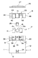
【図3】本装置の部分断面分解斜視図である。
【符号の説明】
1 本体ケーシング
2 熱交換エレメント
S 給気
E,E1,E2 排気
10 天板
15 モータ
16 給気用羽根車
17 排気用羽根車
18 ファンケーシング
21,22 羽根車室
23 モータ室
51 吸込口
53 凹部
55 主風路(モータ室を経由しない風路)
56 副風路(モータ室を経由する風路)[0001]
BACKGROUND OF THE INVENTION
The present invention relates to a ceiling-embedded heat exchange ventilator that ventilates while exchanging heat between air supply from the outside and exhaust from the room.
[0002]
[Prior art]
In the heat exchange ventilator described above, the flow of supply air and exhaust gas that intersect at the heat exchange element is generated by a centrifugal fan such as a sirocco fan or a turbo fan, respectively. This type of fan includes a centrifugal impeller and a fan casing that houses the impeller.
[0003]
Usually, in this type of fan, an impeller chamber that houses an impeller and a motor chamber that houses a motor for driving the impeller are independently configured. It has been desired to prevent the heat generated by the stagnation.
Conventionally, ventilating fans for exhaust purposes only have been provided that use both suction type blades as a centrifugal fan and suck in room air from both the motor room side and the opposite side (actual fairness) No. 6-3321).
[0004]
[Problems to be solved by the invention]
However, in the above-mentioned publication, both suction type blades must be used, which increases the manufacturing cost.
By the way, if the air is flowing even if the air volume is small, it is sufficient for cooling the motor, but if too much air is applied to the motor, a lot of dust adheres to the drive shaft of the motor and the bearing supporting it, It tends to reduce the life of the bearing.
[0005]
On the other hand, in the above-described double-suction type impeller, since it is generally difficult to make a difference in the suction air volume from both sides, the air volume passing through the motor cannot be set very small. Therefore, dust or the like tends to adhere to the drive shaft of the motor.
Accordingly, an object of the present invention is to provide a heat exchange ventilator that can be manufactured at low cost and can suppress the adhesion of dust and the like to a drive shaft of a motor.
[Means for Solving the Problems]
To achieve the above objective,
1) The invention of
In a heat exchange ventilator that accommodates a pair of fans that respectively generate a heat exchange element and a flow of air supply and exhaust that intersect at the heat exchange element in a box-shaped main body casing,
At least one fan is composed of a single-suction impeller that is coaxially connected to the motor and sucks air from the opposite side of the motor, and a fan casing that defines an impeller chamber that houses the impeller. At least a part of the motor chamber containing the motor is partitioned by the fan casing, and the impeller chamber forms a suction port corresponding to the suction side of the stored impeller. air passage passing through the motor chamber and sucked air through the air passage without passing through the motor chamber, the fan casing (18) first and second split bodies which are bisected vertically from (19,20) Thus, the three side surfaces of the divided bodies (19, 20) are positioned in contact with the corresponding three side plates (11 to 13) of the main casing (1) .
[0006]
In the above configuration, the air passage that passes through the motor chamber and the air passage that does not pass through the motor chamber are both guided to the same side of the impeller, and an inexpensive single-suction impeller according to this configuration. Was used. Moreover, since the impeller is a single suction type, the ratio of the air volume of the air passage that passes through the motor chamber and the air volume of the air passage that does not pass through the motor chamber can be set as desired. As a result, the dust can be prevented from adhering to the drive shaft of the motor.
[0007]
In addition, since a part of the motor chamber is partitioned by the fan casing, parts costs and assembly costs can be reduced as compared with the case where a separate member is provided to partition the motor chamber, thereby reducing manufacturing costs. it can.
2) The invention according to
2. The heat exchange ventilator according to
[0008]
In the above configuration, the communication space included in the first exhaust air passage can be formed between both of them simply by incorporating the fan casing into the main body casing. Therefore, the communication space is formed using a member different from the above. Compared to the case, the manufacturing cost can be reduced through the reduction of the component cost and the assembly cost .
[0010]
DETAILED DESCRIPTION OF THE INVENTION
FIG. 1 is an exploded perspective view showing a schematic configuration of a heat exchange ventilator according to an embodiment of the present invention, FIG. 2 is a partially broken perspective view of the apparatus viewed from below during maintenance, and FIG. It is a fragmentary sectional exploded side view for demonstrating the assembly process of this apparatus.
[0011]
Referring to FIG. 1, the present heat exchange ventilator A (hereinafter simply referred to as a ventilator A) includes an outdoor air supply S (indicated by solid arrows in the figure) and an indoor exhaust E (in the figure, Ventilation while exchanging heat via the
[0012]
Referring to FIG. 1, flanges 1 b are formed on the periphery of the opening 1 a on the lower surface of the
The opening 1a is covered with a grid-like grill 60 (see FIG. 2). The opening 1a blows outdoor air into the room by the
[0013]
The
[0014]
The supply fan for generating the supply air flow and the exhaust fan for generating the exhaust flow are configured as an integrated fan unit U.
The fan unit U includes a double-
[0015]
A
[0016]
The
[0017]
The
The
[0018]
A through
[0019]
A through
[0020]
In the figure, 49 is a suction port of the air
A
[0021]
In the ventilator A, outdoor air is supplied from the
On the other hand, the indoor air passes through the main air passage 55 (the air passage that sequentially follows the hatched arrow E1) and the
[0022]
The
Next, with reference to FIG. 3, a process of assembling the present ventilation device A will be described. The
[0023]
Next, after the
Next, the second divided
[0024]
A positioning stopper (not shown) for preventing the fan casing 18 from moving toward the
[0025]
Thus, in this embodiment, after each component which comprises the fan unit U is inserted in the main body casing turned upside down in order and stacked, the fan unit U is completed by attaching the
[0026]
Further, when the divided
[0027]
In particular, since both fans for supplying and exhausting air are configured as an integrated fan unit U, both fans can be assembled together by a simple stacking operation.
In addition, by removing the
[0028]
In the present embodiment, the air passage is configured so that the
[0029]
In addition, since the peripheral wall of the
In addition, a
[0030]
Further, since the peripheral walls of the two
In this embodiment, both the air supply and exhaust fans are collectively configured as a fan unit. However, each fan is configured by an individual motor, an impeller, and a fan casing, and each fan is configured separately. You may do it.
[0031]
Moreover, in the said embodiment, although the thing of the ceiling embedding type of the type which has arrange | positioned the
[0032]
Further, in the above embodiment, the maintenance of the
[0033]
【The invention's effect】
According to the first aspect of the present invention, the air passage is configured such that the air passage passing through the motor chamber and the air passage not passing through the motor chamber are both guided to the same side of the impeller, and an inexpensive single suction is provided accordingly. Since the shaped impeller is used, the manufacturing cost can be reduced. In addition, because it is a single suction type, the air volume passing through the motor chamber can be set to the minimum necessary air volume that can cool the motor, and as a result, the adhesion of dust to the motor drive shaft, etc. can be suppressed, As a result, the lifetime of the drive shaft and the bearing that supports the drive shaft can be improved.
Further, when the divided parts of the fan casing are incorporated in the main body casing, the side plates of the main body casing can be used as guide surfaces and positioning surfaces, so that assembly is facilitated. Compared with the case where the members constituting the guide surface and the positioning surface are separately formed, the manufacturing cost can be further reduced by reducing the number of parts and the number of assembly steps.
[0034]
In the invention described in
[Brief description of the drawings]
FIG. 1 is an exploded perspective view showing a schematic configuration of a heat exchange ventilator according to an embodiment of the present invention.
FIG. 2 is a partially broken perspective view of the apparatus as viewed from below during maintenance.
FIG. 3 is a partial cross-sectional exploded perspective view of the apparatus.
[Explanation of symbols]
DESCRIPTION OF
56 Secondary air passage (air passage via motor room)
Claims (2)
少なくとも一のファンは、モータ(15)と同軸に連結され且つモータ(15)と反対側から空気を吸い込む片吸込形の羽根車(17)と、この羽根車(17)を収容した羽根車室(22)を区画形成したファンケーシング(18)とで構成され、
上記ファンケーシング(18)によって、上記モータ(15)を収容したモータ室(23)の少なくとも一部が区画され、
上記羽根車室(22)は、収容した羽根車(17)の吸込側に対応して吸込口(51)を形成しており、この吸込口(51)へは、モータ室(23)を経由する風路(56)およびモータ室(23)を経由しない風路(55)を介して空気が吸い込まれ、
上記ファンケーシング (18) は上下に二分割された第1および第2の分割体 (19,20) からなり、
各分割体 (19,20) の3つの側面が本体ケーシング (1) の対応する3つの側板 (11 〜 13) にそれぞれ当接して位置決めされることを特徴とする熱交換換気装置。In a box-shaped main casing (1), a heat exchange element (2) and a pair of air supply (S) and exhaust (E, E1, E2) flows that intersect at the heat exchange element (2) are generated. In a heat exchange ventilator containing a fan,
At least one fan is coaxially connected to the motor (15) and is a single-suction impeller (17) that sucks air from the opposite side of the motor (15), and an impeller chamber housing the impeller (17) (22) and a fan casing (18) with compartments formed,
The fan casing (18) defines at least a part of the motor chamber (23) containing the motor (15),
The impeller chamber (22) forms a suction port (51) corresponding to the suction side of the housed impeller (17), and this suction port (51) is routed through the motor chamber (23). The air is sucked in through the air passage (56) and the air passage (55) that does not pass through the motor chamber (23) ,
The fan casing (18) is composed of first and second divided bodies (19, 20) which are divided into upper and lower parts ,
Heat exchange ventilator, characterized in that three sides are positioned in contact to corresponding three side plate of the main casing (1) (11 to 13) of each divided member (19, 20).
Priority Applications (1)
| Application Number | Priority Date | Filing Date | Title |
|---|---|---|---|
| JP00958096A JP3660955B2 (en) | 1996-01-23 | 1996-01-23 | Heat exchange ventilator |
Applications Claiming Priority (1)
| Application Number | Priority Date | Filing Date | Title |
|---|---|---|---|
| JP00958096A JP3660955B2 (en) | 1996-01-23 | 1996-01-23 | Heat exchange ventilator |
Publications (2)
| Publication Number | Publication Date |
|---|---|
| JPH09196428A JPH09196428A (en) | 1997-07-31 |
| JP3660955B2 true JP3660955B2 (en) | 2005-06-15 |
Family
ID=11724256
Family Applications (1)
| Application Number | Title | Priority Date | Filing Date |
|---|---|---|---|
| JP00958096A Expired - Fee Related JP3660955B2 (en) | 1996-01-23 | 1996-01-23 | Heat exchange ventilator |
Country Status (1)
| Country | Link |
|---|---|
| JP (1) | JP3660955B2 (en) |
Families Citing this family (2)
| Publication number | Priority date | Publication date | Assignee | Title |
|---|---|---|---|---|
| KR100628090B1 (en) * | 2005-05-11 | 2006-09-26 | 엘지전자 주식회사 | Air-conditioning system |
| KR101299766B1 (en) * | 2009-04-27 | 2013-08-23 | 미쓰비시덴키 가부시키가이샤 | Heat exchanging ventilator |
-
1996
- 1996-01-23 JP JP00958096A patent/JP3660955B2/en not_active Expired - Fee Related
Also Published As
| Publication number | Publication date |
|---|---|
| JPH09196428A (en) | 1997-07-31 |
Similar Documents
| Publication | Publication Date | Title |
|---|---|---|
| KR20120012798A (en) | Heat exchanging ventilator | |
| KR20070060501A (en) | Air conditioner | |
| JP3660955B2 (en) | Heat exchange ventilator | |
| KR100662343B1 (en) | ventilating system | |
| JP3660954B2 (en) | Heat exchange ventilator | |
| JPS62218747A (en) | Ceiling embedded type ventilator | |
| KR102322362B1 (en) | Air circulator having dual fan motor | |
| JP2019184176A (en) | Heat exchange type ventilation device | |
| JP2000130814A (en) | Air conditioner | |
| JP4456326B2 (en) | Air conditioner | |
| KR101028950B1 (en) | Ventilation apparatus | |
| JP3165013B2 (en) | Heat exchange type ventilation fan | |
| JP2004085149A (en) | Heat-exchange ventilation device | |
| JPH0136030Y2 (en) | ||
| JP4544410B2 (en) | Air conditioner | |
| JPH05180463A (en) | Outdoor fan construction for air conditioner of integration type | |
| JP2003014272A (en) | Air conditioning ventilator | |
| JP6948515B2 (en) | Heat exchange type ventilation system | |
| JP3268919B2 (en) | Air conditioner blower | |
| JPH068320Y2 (en) | Blower mounting device | |
| JP2002022233A (en) | Air conditioning apparatus | |
| JPH0989339A (en) | Heat exchange ventilator | |
| KR20020026724A (en) | The air conditioner attached a ventilation device | |
| JPH1078250A (en) | Air supply apparatus | |
| JP2023133665A (en) | Ventilation device |
Legal Events
| Date | Code | Title | Description |
|---|---|---|---|
| A977 | Report on retrieval |
Free format text: JAPANESE INTERMEDIATE CODE: A971007 Effective date: 20040930 |
|
| A131 | Notification of reasons for refusal |
Free format text: JAPANESE INTERMEDIATE CODE: A131 Effective date: 20041109 |
|
| A521 | Written amendment |
Free format text: JAPANESE INTERMEDIATE CODE: A523 Effective date: 20050111 |
|
| TRDD | Decision of grant or rejection written | ||
| A01 | Written decision to grant a patent or to grant a registration (utility model) |
Free format text: JAPANESE INTERMEDIATE CODE: A01 Effective date: 20050208 |
|
| A61 | First payment of annual fees (during grant procedure) |
Free format text: JAPANESE INTERMEDIATE CODE: A61 Effective date: 20050221 |
|
| FPAY | Renewal fee payment (event date is renewal date of database) |
Free format text: PAYMENT UNTIL: 20080401 Year of fee payment: 3 |
|
| FPAY | Renewal fee payment (event date is renewal date of database) |
Free format text: PAYMENT UNTIL: 20090401 Year of fee payment: 4 |
|
| FPAY | Renewal fee payment (event date is renewal date of database) |
Free format text: PAYMENT UNTIL: 20100401 Year of fee payment: 5 |
|
| FPAY | Renewal fee payment (event date is renewal date of database) |
Free format text: PAYMENT UNTIL: 20100401 Year of fee payment: 5 |
|
| FPAY | Renewal fee payment (event date is renewal date of database) |
Free format text: PAYMENT UNTIL: 20110401 Year of fee payment: 6 |
|
| FPAY | Renewal fee payment (event date is renewal date of database) |
Free format text: PAYMENT UNTIL: 20120401 Year of fee payment: 7 |
|
| FPAY | Renewal fee payment (event date is renewal date of database) |
Free format text: PAYMENT UNTIL: 20130401 Year of fee payment: 8 |
|
| FPAY | Renewal fee payment (event date is renewal date of database) |
Free format text: PAYMENT UNTIL: 20140401 Year of fee payment: 9 |
|
| LAPS | Cancellation because of no payment of annual fees |