JP3660147B2 - Abnormality detection device for exhaust secondary air supply device - Google Patents
Abnormality detection device for exhaust secondary air supply device Download PDFInfo
- Publication number
- JP3660147B2 JP3660147B2 JP34687298A JP34687298A JP3660147B2 JP 3660147 B2 JP3660147 B2 JP 3660147B2 JP 34687298 A JP34687298 A JP 34687298A JP 34687298 A JP34687298 A JP 34687298A JP 3660147 B2 JP3660147 B2 JP 3660147B2
- Authority
- JP
- Japan
- Prior art keywords
- value
- air pump
- electric air
- current value
- current
- Prior art date
- Legal status (The legal status is an assumption and is not a legal conclusion. Google has not performed a legal analysis and makes no representation as to the accuracy of the status listed.)
- Expired - Fee Related
Links
Images


Landscapes
- Exhaust Gas After Treatment (AREA)
Description
【0001】
【発明の属する技術分野】
本発明は、エンジンの排気ガス中の有害成分を減少させるべく排気通路に電動エアーポンプで二次エアーを供給する排気二次エアー供給装置に関し、特に、その電動エアーポンプやエアー供給通路、あるいは前記エアー供給通路に設けた流量制御弁の異常状態を検出するための異常検出装置に関する。
【0002】
【従来の技術】
排気二次エアー供給装置の異常を検出する手法として、排気通路に設けたO2 センサを使用するものが知られている。これは、排気二次エアー供給装置が正常に機能していれば、排気通路への二次エアーの供給によりO2 センサが酸素過剰状態になり、リーン状態を示す信号を出力することを利用するものである。
【0003】
また排気二次エアー供給装置の異常検出装置として、特開平8−61051号公報に記載されたものが知られている。これは、電動エアーポンプの電流値および電圧値から電力値を算出し、この電力値が所定の範囲内にあるか否かにより電動エアーポンプの異常状態を検出するものである。
【0004】
【発明が解決しようとする課題】
ところで電動エアーポンプに給電するバッテリが充電不足の状態にある場合や劣化している場合、あるいは消費電力が大きい電動パワーステアリング装置、ディスチャージヘッドライト、エアコンディショナー、パワーウインドウ装置等を作動させた場合、つまりバッテリの充放電バランスが崩れた場合に、電動エアーポンプを駆動する電圧の低下により消費電流が低下するため、この消費電流をそのまま用いて電動エアーポンプの異常状態の検出を行うと検出精度が低下する虞がある。
【0005】
本発明は前述の事情に鑑みてなされたもので、バッテリの充放電バランスが崩れた場合にも排気二次エアー供給装置の異常状態を精度良く検出できるようにすることを目的とする。
【0006】
【課題を解決するための手段】
前記目的を達成するために、請求項1に記載された発明によれば、エンジンの排気通路に排気二次エアーを供給する電動エアーポンプと、この電動エアーポンプを含む電気負荷に給電するバッテリの電圧値を検出する電圧検出手段と、前記電動エアーポンプに流れる電流値を検出する電流検出手段と、この電流検出手段で検出した電流値に基づいて異常状態を検出する異常検出手段とを備えた排気二次エアー供給装置の異常検出装置であって、前記異常検出手段は、前記電流値を前記電圧値に応じて補正することで補正電流値を算出して、その補正電流値に基づいて異常状態を検出するものにおいて、前記異常検出手段が、前記電動エアーポンプの運転に伴う前記補正電流値の変化に基づいて異常状態を検出すると共に、前記電流検出手段で検出した電流値の変化が敷居値を越えた場合に異常状態の検出を一時中止し、その一時中止を実行するか否かの判断は、前記電動エアーポンプの起動後、電動エアーポンプ突入電流安定待ちのための設定値と電気負荷変動安定待ちのための設定値とに基づいて設定される設定時間の経過を待って行われることを特徴とする、排気二次エアー供給装置の異常検出装置が提案される。
【0007】
上記構成によれば、電動エアーポンプを含む電気負荷に給電するバッテリの電圧値が変化しても、電動エアーポンプに流れる電流値を前記電圧値に応じて補正して補正電流値を算出し、この補正電流値の変化に基づいて異常状態を検出することにより、バッテリの電圧値の変化の影響を補償して異常状態を精度良く検出することができる。また異常検出手段は、電流検出手段で検出した電流値の変化が敷居値を越えた場合に異常状態の検出を中止するので、例えば補機類等の電気負荷の突入電流によってバッテリの電圧値が一時的に大きく変化して電流検出手段で検出した電流値の変化が敷居値を越えると、異常検出手段が異常状態の検出を一時中止して、誤検出の発生を未然に防止することができ、この場合において、異常状態検出の一時中止を実行するか否かの判断は、電動エアーポンプの起動後、電動エアーポンプ突入電流安定待ちのための設定値と電気負荷変動安定待ちのための設定値とに基づいて設定される設定時間の経過を待って行われる。
【0008】
【発明の実施の形態】
以下、本発明の実施の形態を、添付図面に示した本発明の実施例に基づいて説明する。 図1〜図12は本発明の一実施例を示すもので、図1は排気二次エアー供給装置の全体構成図、図2は電動エアーポンプ異常検出メインルーチンのフローチャート、図3はIAP自動ヒス付けサブルーチンのフローチャート、図4は制御用IAPUMP算出サブルーチンのフローチャート、図5はモニタ実施許可条件成立判断サブルーチンのフローチャート、図6は電気負荷変動時モニタ一時停止条件サブルーチンのフローチャート、図7は流量特性劣化検知サブルーチンのフローチャート、図8は電動エアーポンプの吐出圧および電流値の関係を各バッテリ電圧値について示すグラフ、図9はバッテリの電圧値VBからIAP補正テーブル値KIAPVBを検索するテーブルを示す図、図10はモニタ実施許可条件成立判断および流量劣化特性検知を説明するタイムチャート、図11はモニタ実施許可条件成立判断を説明するタイムチャート、図12は電気負荷変動時モニタ一時停止条件を説明するタイムチャートである。
【0009】
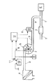
図1に示すように、エンジンEから延びる排気通路1には排気ガスを浄化する排気ガス浄化触媒2が設けられており、この排気ガス浄化触媒2の上流側の排気通路1に排気二次エアー供給装置のエアー供給通路3の下流端が接続される。エアー供給通路3には、その上流側から下流側に向けて、エアクリーナ4と、電動エアーポンプ5と、流量制御弁6とが順次設けられる。本発明の異常検出手段を構成する電子制御ユニットUは、電動エアーポンプ5を駆動するモータ7のON/OFFと、ソレノイド弁よりなる流量制御弁6のON/OFFとを制御するとともに、前記モータ7に流れる電流値を検出する電流センサ8からの信号と、電動エアーポンプ5および電動パワーステアリング装置、ディスチャージヘッドライト、エアコンディショナー、パワーウインドウ装置等の電気負荷9に給電するバッテリ10の電圧値を検出する電圧センサ11からの信号とに基づいて、電動エアーポンプ5、流量制御弁6あるいはエアー供給通路3の異常を検出する。
【0010】
排気二次エアー供給装置は、エンジンEの始動後に所定時間だけ電動エアーポンプ5を駆動して排気通路1にエアーを供給することにより、排気ガス浄化触媒2の活性化を図るとともに排気ガス中の一酸化炭素等の有害成分を酸化して無害化するためのものであり、その際に流量制御弁6は電動エアーポンプ5の非駆動時に閉弁してエアー供給通路3への排気ガスの逆流を防止する。本実施例では、エンジンEの始動後に電動エアーポンプ5が駆動されたとき、これと同時に流量制御弁6を開弁することなく、所定の時間遅れを持たせて流量制御弁6を開弁することにより、電動エアーポンプ5、流量制御弁6あるいはエアー供給通路3の異常を検出するようになっている。以下、その作用を図2〜図7のフローチャートに基づいて説明する。
【0011】
図2のフローチャートは電動エアーポンプ異常検出のメインルーチンを示すもので、先ずステップS1で電流センサ8で検出した電動エアーポンプ5の電流値(AD変換値)IAPにヒステリシスを付与する。即ち、電動エアーポンプ5を駆動するモータ7の回転に伴って電流センサ8が検出する電動エアーポンプ5の電流値IAPは正弦波状に微小変動するため、その変動があたかもノイズのように振る舞って誤検出の原因になる可能性がある。そこで、電流値IAPの微小変動を除去して実質的な変動のみを取り出す処理を行う。このステップS1の詳細は、後から図3のフローチャートに基づいて詳述する。
【0012】
続くステップS2で、電圧センサ11で検出したバッテリ10の電圧値(AD変換値)VBを用いて前記電流値IAPを補正することにより、電動エアーポンプ5および流量制御弁6の制御、あるいは排気二次エアー供給装置の異常検出を行う際に使用する、補正された制御用電流値IAPUMPを算出する。このステップS2の詳細は、後から図4のフローチャートに基づいて詳述する。
【0013】
続くステップS3で、エンジンEの運転条件が、排気二次エアー供給装置の異常検出を行うのに適した条件にあるか否かを判断する。このステップS3の詳細は、後から図5のフローチャートに基づいて詳述する。
【0014】
続くステップS4で、後述するモニタ実施許可条件成立フラグF MCND60Aが「0」にクリアされていてモニタ実施許可条件が成立していなければ、ステップS7で、後述する一次検知判定値ISAVOおよび二次検知判定値DISAVを初期値0にセットするとともに、後述する仮正常判定フラグF KOK60Aを初期値「0」にクリアする。一方、前記ステップS4で、モニタ実施許可条件成立フラグF MCND60Aが「1」にセットされていてモニタ実施許可条件が成立していれば、ステップS5に移行する。
【0015】
ステップS5で、例えばエアコンディショナ等の電気負荷9の突入電流によってバッテリ10の電圧値VBが一時的に大きく低下したような場合、排気二次エアー供給装置の異常検出を正確に行うことができないため、その異常検出を一時停止する制御を行う。このステップS6の詳細は、後から図6のフローチャートに基づいて詳述する。
【0016】
続くステップS6で、電動エアーポンプ5、流量制御弁6あるいはエアー通路3に異常が発生したか否かを、前記補正された制御用電流値IAPUMPを用いて具体的に検出する。このステップS7の詳細は、後から図7のフローチャートに基づいて詳述する。
【0017】
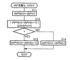
次に、図3のフローチャートに基づいて、前記ステップS1の内容(IAP自動ヒス付け)を具体的に説明する。
【0018】
先ず、ステップS11で、電動エアーポンプ5の電流値(AD変換値)IAPの今回値IAP(n) を、自動ヒステリシス反映前の電流値IAPNの今回値IAPN(n) とする。続くステップS12で、前記自動ヒステリシス反映前の電流値IAPNの今回値IAPN(n) と、自動ヒステリシス反映後の電流値IAPHの前回値IAPH(n-1) との偏差の絶対値|IAPN(n) −IAPH(n-1) |を自動ヒステリシス反映敷居値DIAPHYSと比較し、|IAPN(n) −IAPH(n-1) |≦DIAPHYSが成立して電流値IAPの変動が小さい場合には、その変動がモータ7の回転に伴う変動であると見做し、ステップS13で、自動ヒステリシス反映後の電流値IAPHの前回値IAPH(n-1) を更新せずに、そのまま自動ヒステリシス反映後の電流値IAPHの今回値IAPH(n) とする。一方、前記ステップS12で、|IAPN(n) −IAPH(n-1) |>DIAPHYSが成立して電流値IAPの変動が大きい場合には、その変動がモータ7の回転に伴う変動以外の要因によるものであると判断し、ステップS14で、自動ヒステリシス反映前の電流値IAPNの今回値IAPN(n) を、自動ヒステリシス反映後の電流値IAPHの今回値IAPH(n) とする更新を行う。
【0019】
このように、電動エアーポンプ5の電流値IAPに自動ヒステリシスを付与することにより、モータ7の回転に伴う正弦波状の変動を除去して適切な電流値IAPを得ることができる。
【0020】
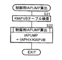
次に、図4のフローチャートに基づいて、前記ステップS2の内容(制御用IAPUMP算出)を具体的に説明する。
【0021】
先ず、ステップS21で、電圧センサ11で検出したバッテリ10の電圧値VBを図9の補正テーブルに適用することにより、IAP補正テーブル値KIAPVBを検索し、このIAP補正テーブル値KIAPVBを前記自動ヒステリシス反映後の電流値IAPHに適用することにより、補正された制御用電流値IAPUMPを次式に基づいて算出する。
【0022】
IAPUMP←IAPH×KIAPVB
図9から明らかなように、補正テーブルから検索されたIAP補正テーブル値KIAPVBは、バッテリ10の電圧値VBが基準となる14V(交流発電機のレギュレート電圧)のときに1.0であり、電圧値VBが基準値14Vを越えると1.0よりも小さくなって制御用電流値IAPUMPは減少方向に補正され、逆に電圧値VBが基準値14Vを下回ると1.0よりも大きくなって制御用電流値IAPUMPは増加方向に補正される。
【0023】
制御用電流値IAPUMPの上記特性の意味するところを以下に説明する。
【0024】
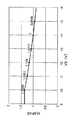
図8は、バッテリ10の電圧値VBを10Vから15Vまで1V毎に変化させながら、電動エアーポンプ5の吐出圧DP(横軸)と、電動エアーポンプ5の電流値IAP(縦軸)との関係を測定した結果を示すものである。同図から明らかなように、各電圧値VBはDP−IAP特性は相互に平行であり、特性ラインの傾き(ΔIAP/ΔDP)の略一定である。また吐出圧DPが一定の場合、バッテリ10の電圧値VBが増加すると電動エアーポンプ5の電流値IAPが増加する。吐出圧DPが10kPa(アイドリング時の背圧相当)であり、かつ電圧値VBが14V(交流発電機のレギュレート電圧相当)である状態を基準状態とし、各々の電圧値VBにおいて10kPaの吐出圧を得るために必要な電流値IAPで、前記基準状態における電流値IAPを除したものが、前記図9のIAP補正テーブル値KIAPVBとなる。
【0025】
従って、バッテリ10の電圧値VBが正常値の14Vであるときに電動エアーポンプ5の電流値IAPは約35Aになるが、例えば電圧値VBが12Vまで低下すると電流値IAPが約30Aになる。前記35Aから30Aへの電流値IAPの低下は異常状態に起因するものではなく、単なるバッテリ10の電圧値VBの変動に起因するものであるため、それを異常状態であると誤認するのを防止するために、30Aの電流値IAPを、電圧値VBが正常値の14Vであるときの電流値35Aに補正する。具体的には、図9の補正テーブルから電圧値VB=12VのときのIAP補正テーブル値KIAPVB=1.159を検索し、このIAP補正テーブル値KIAPVB=1.159を電流値IAP=30Aに乗算することにより、補正された制御用電流値IAPUMP=35Aを得ることができる。
【0026】
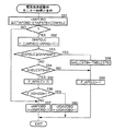
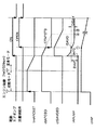
次に、図5のフローチャート並びに図10および図11のタイムチャートに基づいて、前記ステップS3の内容(モニタ実施許可条件成立判断)を具体的に説明する。
【0027】
先ず、ステップS31で、電動エアーポンプシステムモニタ実施許可フラグF GO60Aを参照する。電動エアーポンプシステムモニタ実施許可フラグF GO60Aは、集中管理部で実行される故障検知の結果を表すもので、それが「1」にセットされておらず、何らかの故障が発生していれば、ステップS48で、モニタ実施許可条件成立フラグF MCND60Aを「0」にクリアしてモニタの実施を禁止する。
【0028】
前記ステップS31で、電動エアーポンプシステムモニタ実施許可フラグF GO60Aが「1」にセットされていれば、ステップS32で、通電許可判断フラグF APHTSTPを参照する。通電許可判断フラグF APHTSTPは、始動モードでの冷却水温に基づいて電動エアーポンプ5の作動の許可あるいは禁止を表すもので、それが「1」にセットされていて、従って排気ガス浄化触媒2の活性化を図るために電動エアーポンプ5を駆動する必要がない場合には、ステップS43で、後述するHOT−IDLEでのモニタ実施許可フラグF APOBDHTを「0」にクリアした後に、ステップS48でモニタ実施許可条件成立フラグF MCND60Aを「0」にクリアしてモニタの実施を禁止する。
【0029】
前記ステップS32で、通電許可判断フラグF APHTSTPが「1」にセットされておらず、従って電動エアーポンプ5の作動が許可されており、かつステップS33で、エンジンEが始動モードにあれば、即ちエンジン回転数Neが500rpm未満であれば、前記ステップS43を経て前記ステップS48でモニタ実施許可条件成立フラグF MCND60Aを「0」にクリアしてモニタの実施を禁止する。
【0030】
前記ステップS33で、エンジン回転数Neが500rpm以上であって既に始動モードを脱して基本モード(図10参照)に入っていれば、ステップS34で、基本モード安定待ちタイマtmAPCSSTがタイムアップしているか否かを判断する。基本モード安定待ちタイマtmAPCSSTは、エンジンEの始動と同時にセットされ、基本モードに入ると同時にカウントダウンを開始するもので、それがタイムアップしたときには、基本モードに入ってからTMAPCSSTが経過していてアイドリング状態が安定しているものと判断される。
【0031】
前記ステップS34で、基本モード安定待ちタイマtmAPCSSTがタイムアップしていないときは、ステップS46で、現在の制御用電流値IAPUMPを後述する第1基準電流値IAP0とするとともに、ステップS47で後述する一次検知故障確定カウンタctAPOBDをループ毎に設定値CTAPOBDにセットした後、前記ステップS48でモニタ実施許可条件成立フラグF MCND60Aを「0」にクリアしてモニタの実施を禁止する。
【0032】
前記ステップS34で、基本モード安定待ちタイマtmAPCSSTがタイムアップしているときは、ステップS35で、大気圧PAが高地に対応する敷居値PAFS60A以上であり、かつ冷却水温TWが低水温に対応する敷居値TWFS60A以上であるか否かを判断する。その結果、前記両条件の少なくとも一方が不成立の場合、即ち大気圧が低いか、あるいは冷却水温が低い場合にはステップS44に移行する。ステップS44で、モニタ実施ディレータイマtmFS60ADのタイムアップを待ち、ステップS45で、モニタ実施安定待ちタイマtmFS60Aを設定値TMFS60Aにセットし、かつ一次検知故障確定カウンタctAPOBDを0にセットした後に、前記ステップS48でモニタ実施許可条件成立フラグF MCND60Aを「0」にクリアしてモニタの実施を禁止する。
【0033】
このように、モニタ実施ディレータイマtmFS60ADのタイムアップを待ってモニタの実施を禁止することにより、前記ステップS35の判断結果がYESおよびNOの間で変化したときに、モニタの実施および停止が頻繁に繰り返されるのを防止することができる。
【0034】
前記ステップS35の各条件が成立すると、ステップS36で、モニタ実施ディレータイマtmFS60ADを設定値TMFS60ADにセットした後、ステップS37で、エンジンEがアイドリング状態にあり、車速パルスVpが0であり、かつバッテリ10の電圧値VBがモニタ実施下限敷居値VBFS60A(10.0V)以上であるか否かを判断し、そのうち何れかの条件が成立しなければ、前記ステップS45を経て前記ステップS48でモニタ実施許可条件成立フラグF MCND60Aを「0」にクリアしてモニタの実施を禁止する。
【0035】
前記ステップS37の全ての条件が成立したとき、続くステップS38で、前記HOT−IDLEでのモニタ実施許可フラグF APOBDHTを参照する。HOT−IDLEでのモニタ実施許可フラグF APOBDHTは、排気ガス浄化触媒2の活性化を図るために電動エアーポンプ5を駆動した際のモニタが不成立になった場合に、排気ガス浄化触媒2の活性化する目的でなく、再度モニタの実施を図る目的で電動エアーポンプ5の駆動を許可するフラグである。
【0036】
前記ステップS38で、HOT−IDLEでのモニタ実施許可フラグF APOBDHTが「1」にセットされておらず、従って排気ガス浄化触媒2の活性化を図るために電動エアーポンプ5が駆動される場合には、ステップS39をスキップしてステップS40に移行する。ステップS40で、前記モニタ実施安定待ちタイマtmFS60Aがタイムアップするのを待って、ステップS41で、モニタ実施許可条件成立フラグF MCND60Aを「1」にセットしてモニタの実施を許可する。
【0037】
一方、前記ステップS38で、HOT−IDLEでのモニタ実施許可フラグF APOBDHTが「1」にセットされており、従って排気ガス浄化触媒2の活性化を図るためでなく電動エアーポンプ5が駆動される場合には、ステップS39に移行して電動エアーポンプ通電時間カウンタctAPがタイムアップしているか否かを判断する。電動エアーポンプ通電時間カウンタctAPは、排気ガス浄化触媒2の活性化を図るために必要な電動エアーポンプ5の駆動時間であり、エンジンEの始動と同時にマップ検索される。この電動エアーポンプ通電時間カウンタctAPがタイムアップするまでは、前記ステップS45を経て前記ステップS48でモニタ実施許可条件成立フラグF MCND60Aを「0」にクリアしてモニタの実施を禁止する。
【0038】
また前記ステップS39で、電動エアーポンプ通電時間カウンタctAPがタイムアップすると、ステップS40で、モニタ実施安定待ちタイマtmFS60Aがタイムアップするのを待って、ステップS41で、モニタ実施許可条件成立フラグF MCND60Aを「1」にセットしてモニタの実施を許可する。
【0039】
次に、エンジンEの始動直後にモニタが不成立になった場合の作用を、図11のタイムチャートに基づいて更に説明する。
【0040】
エンジンEの始動後に電動エアーポンプ5が駆動され、更に流量制御弁6が開弁した後、二次検知故障確定カウンタctSAVOBDがタイムアップしてモニタが完了する前に、例えばエンジン回転数Neがアイドル回転数を越えてモニタが不成立になったとする(ステップS37参照)。その後、エンジン回転数Neがアイドル回転数以下になると、モニタ実施安定待ちタイマtmFS60Aのタイムアップを待った後に、モニタの実施を目的として電動エアーポンプ5の再駆動および流量制御弁6の再開弁が実行される。
【0041】
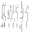
次に、図6のフローチャート並びに図10および図12のタイムチャートに基づいて、前記ステップS5の内容(電気負荷変動時モニタ一時停止条件)を具体的に説明する。
【0042】
先ずステップS51で、電動エアーポンプ5の起動と共にカウントダウンされる一次検知故障確定カウンタctAPOBD(図10参照)のカウント値が、CTAPOBD−CTAPSTB+CTAPELC以下になると、モニタの一時停止を実行すべきか否かを判断するためにステップS52に移行する。ここで、CTAPOBDは一次検知故障確定のための設定値であり、CTAPSTBは電動エアーポンプ突入電流安定待ちのための設定値であり、CTAPELCは電気負荷変動安定待ちのための設定値である。
【0043】
続くステップS52で、電気負荷変動レベル判定値DIAPELCを、自動ヒステリシス反映後の電流値IAPHの今回値IAPH(n) と前回値IAPH(n-1) との差の絶対値|IAPH(n) −IAPH(n-1) |として算出する。
【0044】
DIAPELC←|IAPH(n) −IAPH(n-1) |
続くステップS53で、電気負荷変動レベル判定値DIAPELCをモニタ一時停止敷居値DIAPSSPと比較し、DIAPELC≧DIAPSSPが不成立で電気負荷変動レベルが小さい場合であって、かつステップS54で、電気負荷変動安定待ちタイマtmELCSTBがタイムアップしていれば、ステップS55で、モニタ一時停止フラグF APELCを「0」にクリアしてモニタの一時停止を不実行とする。
【0045】
一方、前記ステップS53で、DIAPELC≧DIAPSSPが成立して電気負荷変動レベルが大きい場合には、ステップS58で電気負荷変動安定待ちタイマtmELCSTBを設定値TMELCSTBにセットするとともに、ステップS59で、モニタ一時停止フラグF APELCを「1」にセットしてモニタ一の一時停止を実行する。前記ステップS53で、DIAPELC≧DIAPSSPが不成立で電気負荷変動レベルが小さい場合でも、ステップS54で、電気負荷変動安定待ちタイマtmELCSTBがカウント中であれば、同様にステップS59で、モニタ一時停止フラグを「1」にセットしてモニタの一時停止を実行する。このように、モニタの一時停止が一旦実行されると、少なくとも電気負荷変動安定待ちタイマtmELCSTBがタイムアップするまでの間モニタの一時停止を継続することにより、頻繁なモニタの停止・実行の繰り返しを防止することができる。
【0046】
以上のように、例えばエアコンディショナーのような消費電力の大きい電気負荷9がONしたときに、その突入電流の影響で電動エアーポンプ5の電流値IAPが瞬間的に大きく変動した場合に、モニタを一時停止することにより、異常状態の誤検出を未然に防止することができる。
【0047】
而して、前記ステップS55で、モニタ一時停止フラグが「0」にクリアされたとき、ステップS56で、仮正常判定フラグF KOK60Aが「1」にセットされていなければ、即ち図10の (1)位置の前であれば、ステップS57で、一時検知故障確定カウンタctAPOBDをデクリメントし、またステップS56で、仮正常判定フラグF KOK60Aが「1」にセットされていれば、即ち (1)位置の後であれば、ステップS60で二次検知故障確定カウンタctSAVOBDをデクリメントする。
【0048】
次に、図7のフローチャートおよび図10のタイムチャートに基づいて、前記ステップS6の内容(流量特性劣化検知)を具体的に説明する。
【0049】
先ずステップS61で、モニタ一時停止フラグF APELCが「0」にクリアされていてモニタの一時停止中でなく、ステップS62で、一次検知故障確定カウンタctAPOBDがカウント中であれば、ステップS63で、二次検知故障確定カウンタctSAVOBDをループ毎に設定値CTSAVOBDにセットする。続くステップS64で、仮正常判定フラグF KOK60Aが「1」にセットされておらず、かつステップS65で、一次検知故障確定カウンタctAPOBDが、CTAPOBD−CTAPSTB(一次検知電動エアーポンプ突入電流安定待ちカウンタ)以下になれば、即ち電動エアーポンプ5が起動してから安定待ち時間が経過して制御用電流値IAPUMPが安定すると(図10の(1)参照)、ステップS66に移行する。
【0050】
ステップS66で、制御用電流値IAPUMPから電動エアーポンプ5の停止時の第1基準電流値IAP0を減算した第1偏差DIAPを算出するとともに、ステップS67で、そのときの制御用電流値IAPUMPを第2基準電流値ISAVOとする。続くステップS68で、前記第1偏差DIAPが下限値DIAPOKLおよび上限値DIAPOKH間にあるか否かを判定する。その判定の結果、前記第1偏差DIAPが下限値DIAPOKLおよび上限値DIAPOKH間にあれば、ステップS69で、電動エアーポンプ5が一応正常であると判断して前記仮正常判定フラグF KOK60Aを「1」にセットし、ステップS70で、一次検知故障確定カウンタctAPOBDを0にセットする。
【0051】
このように、電動エアーポンプ5が起動してから安定待ち時間が経過して制御用電流値IAPUMPが安定したとき、その制御用電流値IAPUMPと電動エアーポンプ5の停止時の第1基準電流値IAP0との第1偏差DIAPが所定範囲に納まっていれば、電動エアーポンプ5が正常に作動していると判断することができる。前記第1偏差DIAPが異常に小さければ 電動エアーポンプ5に対する通電が行われていない可能性があり、また前記第1偏差DIAPが異常に大きければ電動エアーポンプ5がロック等の過負荷状態になって大電流が流れている可能性がある。
【0052】
一方、ステップS62で、一次検知故障確定カウンタctAPOBDがタイムアップし(図10の (2)参照)、かつステップS71で、仮正常判定フラグF KOK60Aが「1」にセットされていない場合には、図10の(1)において前記第1偏差DIAPが所定範囲に納まらなかったことになり、ステップS72で、何らかの異常があると判断して異常判定フラグF FSD60Aを「1」にセットするとともに、ステップS78で異常検出完了フラグF DONE60Aを「1」にセットして異常検出を終了させる。
【0053】
一方、ステップS71で仮正常判定フラグF KOK60Aが「1」にセットされていれば、続くステップS73〜S77で流量制御弁6およびエアー供給通路3の異常検出を実行する。
【0054】
先ずステップS73で、前記ステップS67で算出した第2基準電流値ISAVOから現在の制御用電流値IAPUMPを減算した第2偏差DISAVを算出し、続くステップS74で、前記第2偏差DISAVが二次検知正常判定敷居値DISAVOK以上であれば、ステップS75で流量制御弁6およびエアー供給通路3が正常であると判断し、正常判定フラグF OK60Aを「1」にセットした後に、ステップS78で異常検出完了フラグF DONE60A「1」にセットして異常検出を終了させる。
【0055】
一方、前記ステップS74で、前記第2偏差DISAVが二次検知正常判定敷居値DISAVOK未満であり、かつステップS76で、二次検知故障確定カウンタctSAVOBDがタイムアップしたとき(図10の(3)参照)、ステップS77で流量制御弁6あるいはエアー供給通路3が異常であると判断し、異常判定フラグF FSD60Aを「1」にセットした後に、ステップS78で異常検出完了フラグF DONE60Aを「1」にセットして異常検出を終了させる。
【0056】
このように、一次検知故障確定カウンタctAPOBDがタイムアップし、流量制御弁6が開弁してから安定待ち時間が経過して図10の (2)の状態になったとき、流量制御弁6が閉弁状態から開弁状態に正常に移行し、かつエアー供給通路3に詰まりや破損がなければ、電動エアーポンプ5の負荷が減少するために前記第2偏差DISAVが二次検知正常判定敷居値DISAVOK以上になるはずである。しかしながら、流量制御弁6が故障により開弁しない場合、あるいは流量制御弁6が開弁しても該流量制御弁6の上流のエアー供給通路3が詰まっている場合には電動エアーポンプ5の負荷が変化しないため、前記第2偏差DISAVが二次検知正常判定敷居値DISAVOK未満になって異常を検出することができる。また流量制御弁6が初めから開弁故障している場合、あるいは電動エアーポンプ5および流量制御弁6間のエアー供給通路3が破れている場合には、流量制御弁6を開弁する信号を出力しても電動エアーポンプ5の負荷が変化しないため、前記第2偏差DISAVが二次検知正常判定敷居値DISAVOK未満になって異常を検出することができる。
【0057】
以上、本発明の実施例を詳述したが、本発明はその要旨を逸脱しない範囲で種々の設計変更を行うことが可能である。
【0058】
【発明の効果】
以上のように本発明によれば、電動エアーポンプを含む電気負荷に給電するバッテリの電圧値が変化しても、電動エアーポンプに流れる電流値を前記電圧値に応じて補正して補正電流値を算出し、この補正電流値の変化に基づいて異常状態を検出することにより、バッテリの電圧値の変化の影響を補償して異常状態を精度良く検出することができる。
【0059】
また補機類等の電気負荷の突入電流によってバッテリの電圧値が一時的に大きく変化して電流検出手段で検出した電流値の変化が敷居値を越えると、異常検出手段が異常状態の検出を中止するので、誤検出の発生を未然に防止することができ、この場合において、異常状態検出の一時中止を実行するか否かの判断は、電動エアーポンプの起動後、電動エアーポンプ突入電流安定待ちのための設定値と電気負荷変動安定待ちのための設定値とに基づいて設定される設定時間の経過を待って行われる。従って、例えばエアコンディショナーのような消費電力の大きい電気負荷がONしたときに、その突入電流の影響で電動エアーポンプの電流値が瞬間的に大きく変動した場合に、モニタを一時停止することにより、異常状態の誤検出を未然に防止することができる。
【図面の簡単な説明】
【図1】 排気二次エアー供給装置の全体構成図
【図2】 電動エアーポンプ異常検出メインルーチンのフローチャート
【図3】 IAP自動ヒス付けサブルーチンのフローチャート
【図4】 制御用IAPUMP算出サブルーチンのフローチャート
【図5】 モニタ実施許可条件成立判断サブルーチンのフローチャート
【図6】 電気負荷変動時モニタ一時停止条件サブルーチンのフローチャート
【図7】 流量特性劣化検知サブルーチンのフローチャート
【図8】 電動エアーポンプの吐出圧および電流値の関係を各バッテリ電圧値について示すグラフ
【図9】 バッテリの電圧値VBからIAP補正テーブル値KIAPVBを検索するテーブルを示す図
【図10】 モニタ実施許可条件成立判断および流量劣化特性検知を説明するタイムチャート
【図11】 モニタ実施許可条件成立判断を説明するタイムチャート
【図12】 電気負荷変動時モニタ一時停止条件を説明するタイムチャート
【符号の説明】
1 排気通路
5 電動エアーポンプ
8 電流センサ(電流検出手段)
10 バッテリ
11 電圧センサ(電圧検出手段)
DIAPSSP 敷居値
E エンジン
IAP 電流値
IAPUMP 補正電流値
U 電子制御ユニット(異常検出手段)
VB 電圧値[0001]
BACKGROUND OF THE INVENTION
The present invention relates to an exhaust secondary air supply device that supplies secondary air to an exhaust passage with an electric air pump in order to reduce harmful components in engine exhaust gas, and in particular, the electric air pump, the air supply passage, or the above-mentioned The present invention relates to an abnormality detection device for detecting an abnormal state of a flow control valve provided in an air supply passage.
[0002]
[Prior art]
As a method of detecting an abnormality in the exhaust secondary air supply device, an O provided in the exhaust passage is used.2Those using sensors are known. This is because if the exhaust secondary air supply device is functioning normally, the secondary air is supplied to the exhaust passage.2It utilizes the fact that the sensor is in an oxygen-excess state and outputs a signal indicating a lean state.
[0003]
As an abnormality detection device for an exhaust secondary air supply device, one disclosed in Japanese Patent Application Laid-Open No. 8-61051 is known. In this method, a power value is calculated from the current value and voltage value of the electric air pump, and an abnormal state of the electric air pump is detected based on whether or not the power value is within a predetermined range.
[0004]
[Problems to be solved by the invention]
By the way, when the battery that supplies power to the electric air pump is in a state of insufficient charge or has deteriorated, or when the electric power steering device, discharge headlight, air conditioner, power window device, etc. that consumes a large amount of power are operated, In other words, when the charge / discharge balance of the battery is lost, the current consumption decreases due to a decrease in the voltage that drives the electric air pump. May decrease.
[0005]
The present invention has been made in view of the above circumstances, and an object of the present invention is to make it possible to accurately detect an abnormal state of the exhaust secondary air supply device even when the charge / discharge balance of the battery is lost.
[0006]
[Means for Solving the Problems]
In order to achieve the above object, according to the first aspect of the present invention, there is provided an electric air pump that supplies exhaust secondary air to an exhaust passage of an engine, and a battery that supplies electric load including the electric air pump. Voltage detection means for detecting a voltage value, current detection means for detecting a current value flowing through the electric air pump, and an abnormality detection means for detecting an abnormal state based on the current value detected by the current detection means An abnormality detection device for an exhaust secondary air supply device, wherein the abnormality detection means corrects the current value according to the voltage value.by doingCalculate the correction current valueAnd thatCorrection current valueInDetect abnormal conditions based onIn the above, the abnormality detecting means isAn abnormal state is detected based on a change in the correction current value accompanying the operation of the electric air pump.In addition, when the change in the current value detected by the current detection means exceeds the threshold value, the detection of the abnormal state is temporarily stopped, and whether or not to execute the temporary stop is determined after the electric air pump is started. This is performed after the set time set based on the set value for the electric air pump inrush current stabilization wait and the set value for the electric load fluctuation stabilization wait is elapsed.An abnormality detection device for an exhaust secondary air supply device is proposed.
[0007]
According to the above configuration, even if the voltage value of the battery that supplies power to the electric load including the electric air pump changes, the current value flowing through the electric air pump is corrected according to the voltage value, and the corrected current value is calculated. This correction current valuechange ofBy detecting the abnormal state based on the above, it is possible to compensate for the influence of the change in the voltage value of the battery and detect the abnormal state with high accuracy.AlsoThe abnormality detection unit stops detecting the abnormal state when the change in the current value detected by the current detection unit exceeds the threshold value.SoFor example, if the battery voltage value temporarily changes greatly due to the inrush current of an electrical load such as auxiliary machinery, and the change in the current value detected by the current detection means exceeds the threshold value, the abnormality detection means detects the abnormal state.TemporaryCanceldo it,It is possible to prevent false detection.In this case, whether or not to temporarily stop detection of the abnormal condition is determined after the electric air pump is started, the setting value for waiting for the electric air pump inrush current stabilization and the setting for waiting for the electric load fluctuation stabilization This is performed after the set time set based on the value elapses.
[0008]
DETAILED DESCRIPTION OF THE INVENTION
Hereinafter, embodiments of the present invention will be described based on examples of the present invention shown in the accompanying drawings. 1 to 12 show an embodiment of the present invention. FIG. 1 is an overall configuration diagram of an exhaust secondary air supply device, FIG. 2 is a flowchart of an electric air pump abnormality detection main routine, and FIG. 3 is an IAP automatic hysteresis. 4 is a flowchart of a control IAPUMP calculation subroutine, FIG. 5 is a flowchart of a monitor execution permission condition establishment judgment subroutine, FIG. 6 is a flowchart of an electrical load change monitor suspension condition subroutine, and FIG. 7 is a flow characteristic deterioration. FIG. 8 is a graph showing the relationship between the discharge pressure and current value of the electric air pump for each battery voltage value, and FIG. 9 is a diagram showing a table for retrieving the IAP correction table value KIAPVB from the battery voltage value VB. FIG. 10 shows whether the monitor execution permission condition is satisfied and the flow rate deterioration Time chart for explaining the gender detection, FIG. 11 is a time chart, Figure 12 illustrating the monitor implementation permission condition satisfaction judgment is a time chart for explaining the electrical load variation during monitoring pause condition.
[0009]
As shown in FIG. 1, an exhaust
[0010]
The exhaust secondary air supply device activates the exhaust
[0011]
The flowchart of FIG. 2 shows a main routine for detecting abnormality of the electric air pump. First, hysteresis is given to the current value (AD conversion value) IAP of the
[0012]
In subsequent step S2, the current value IAP is corrected using the voltage value (A / D conversion value) VB of the
[0013]
In the subsequent step S3, it is determined whether or not the operating condition of the engine E is a condition suitable for detecting abnormality of the exhaust secondary air supply device. Details of step S3 will be described later based on the flowchart of FIG.
[0014]
In the subsequent step S4, a monitor execution permission condition satisfaction flag F to be described later If MCND 60A is cleared to “0” and the monitor execution permission condition is not satisfied, in step S7, a primary detection determination value ISAVO and a secondary detection determination value DISAV described later are set to an
[0015]
In step S5, if the voltage value VB of the
[0016]
In subsequent step S6, whether or not an abnormality has occurred in the
[0017]
Next, the content of the step S1 (IAP automatic hysteresis) will be specifically described based on the flowchart of FIG.
[0018]
First, in step S11, the current value IAP of the current value (AD conversion value) IAP of the
[0019]
Thus, by giving an automatic hysteresis to the current value IAP of the
[0020]
Next, the contents of step S2 (control IAPUMP calculation) will be specifically described based on the flowchart of FIG.
[0021]
First, in step S21, the voltage value VB of the
[0022]
IAPUMP ← IAPH × KIAPVB
As apparent from FIG. 9, the IAP correction table value KIAPVB retrieved from the correction table is 1.0 when the voltage value VB of the
[0023]
The meaning of the above characteristics of the control current value IAPUMP will be described below.
[0024]
FIG. 8 shows the relationship between the discharge pressure DP (horizontal axis) of the
[0025]
Therefore, when the voltage value VB of the
[0026]
Next, based on the flowchart of FIG. 5 and the time charts of FIG. 10 and FIG. 11, the contents of step S3 (determination of monitoring execution permission condition) will be specifically described.
[0027]
First, in step S31, the electric air pump system monitor execution permission flag F Refer to GO60A. Electric air pump system monitor execution permission flag F The GO 60A represents the result of failure detection executed by the centralized management unit. If it is not set to “1” and any failure has occurred, the monitor execution permission condition establishment flag is set in step S48. F MCND60A is cleared to “0” to prohibit monitoring.
[0028]
In step S31, the electric air pump system monitor execution permission flag F If GO60A is set to "1", in step S32, energization permission determination flag F Reference APHTSTP. Energization permission determination flag F APHTSTP represents permission or prohibition of the operation of the
[0029]
In step S32, the energization permission determination flag F If APHTSTP is not set to “1”, and therefore the operation of the
[0030]
If the engine speed Ne is 500 rpm or more in step S33 and the basic mode (see FIG. 10) has already been entered after exiting the start mode, whether the basic mode stabilization wait timer tmAPCSST has timed out in step S34. Judge whether or not. The basic mode stabilization wait timer tmAPCSST is set at the same time as the start of the engine E, and starts counting down as soon as the basic mode is entered. When the time is up, the TMAPCSST has elapsed since entering the basic mode, and the idling is started. It is judged that the state is stable.
[0031]
If the basic mode stabilization wait timer tmAPCSST has not timed out in step S34, in step S46, the current current value for control IAPUMP is set to a first reference current value IAP0 which will be described later, and a primary which will be described later in step S47. After the detection failure determination counter ctAPOBD is set to the set value CTAPOBD for each loop, the monitor execution permission condition satisfaction flag F is set in step S48. MCND60A is cleared to “0” to prohibit monitoring.
[0032]
When the basic mode stabilization wait timer tmAPCSST has timed out in step S34, in step S35, the atmospheric pressure PA is equal to or higher than the threshold value PAFS 60A corresponding to the high altitude, and the threshold corresponding to the cooling water temperature TW is the low water temperature. It is determined whether or not the value is TWFS 60A or more. As a result, when at least one of the two conditions is not satisfied, that is, when the atmospheric pressure is low or the cooling water temperature is low, the process proceeds to step S44. In step S44, the monitor execution delay timer tmFS60AD waits for time-up. In step S45, the monitor execution stabilization wait timer tmFS60A is set to the set value TMFS60A, and the primary detection failure determination counter ctAPOBD is set to 0. The monitor execution permission condition satisfaction flag F MCND60A is cleared to “0” to prohibit monitoring.
[0033]
Thus, by prohibiting the execution of the monitor after waiting for the monitor execution delay timer tmFS60AD to expire, the execution and the stop of the monitor are frequently performed when the determination result in step S35 changes between YES and NO. It can be prevented from being repeated.
[0034]
When the conditions in step S35 are satisfied, the monitor execution delay timer tmFS60AD is set to the set value TMFS60AD in step S36, and then in step S37, the engine E is idling, the vehicle speed pulse Vp is 0, and the battery It is determined whether or not the voltage value VB of 10 is equal to or greater than the monitor execution lower limit threshold value VBFS60A (10.0 V), and if any of the conditions is not satisfied, the monitor execution permission is allowed in step S48 through step S45. Condition satisfaction flag F MCND60A is cleared to “0” to prohibit monitoring.
[0035]
When all the conditions in step S37 are satisfied, in step S38, the monitor execution permission flag F in the HOT-IDLE is satisfied. Refer to APODHT. Monitor execution permission flag F in HOT-IDLE APODHT is not intended to activate the exhaust
[0036]
In step S38, the monitoring execution permission flag F in HOT-IDLE If APODHT is not set to “1”, and therefore the
[0037]
On the other hand, in step S38, the monitoring execution permission flag F in HOT-IDLE When APODHT is set to “1” and therefore the
[0038]
In step S39, when the electric air pump energization time counter ctAP times out, in step S40, the monitor execution stabilization waiting timer tmFS60A waits for time up. In step S41, the monitor execution permission condition satisfaction flag F MCND 60A is set to “1” to permit monitoring.
[0039]
Next, the operation when the monitor is not established immediately after the start of the engine E will be further described based on the time chart of FIG.
[0040]
After the
[0041]
Next, based on the flowchart of FIG. 6 and the time charts of FIGS. 10 and 12, the content of the step S5 (electric load fluctuation monitor suspension condition) will be specifically described.
[0042]
First, in step S51, when the count value of the primary detection failure confirmation counter ctAPOBD (see FIG. 10) counted down with the activation of the
[0043]
In subsequent step S52, the electric load fluctuation level determination value DIAPELC is set to the current value IAPH of the current value IAPH after the automatic hysteresis is reflected.(n)And the previous value IAPH(n-1)Absolute value of difference from IAPH(n)-IAPH(n-1)Calculate as |.
[0044]
DIAPELC ← | IAPH(n)-IAPH(n-1)|
In subsequent step S53, the electric load fluctuation level determination value DIAPELC is compared with the monitor temporary stop threshold value DIAPSSSP. If the timer tmELCSTB has timed up, in step S55, the monitor pause flag F APELC is cleared to “0”, and the monitor is not suspended.
[0045]
On the other hand, when DIAPELC ≧ DIAPSSSP is established in step S53 and the electric load fluctuation level is large, the electric load fluctuation stabilization waiting timer tmELCSTB is set to the set value TMELCSTB in step S58, and the monitor is temporarily stopped in step S59. Flag F Set APELC to "1"TemporaryPerform a stop. Even if DIAPELC ≧ DIAPSSSP is not established in step S53 and the electric load fluctuation level is small, if the electric load fluctuation stabilization waiting timer tmELCSTB is being counted in step S54, the monitor temporary stop flag is similarly set to “ Set to “1” to suspend the monitor. As described above, once the monitor is paused, the monitor is suspended until at least the electric load fluctuation stabilization wait timer tmELCSTB times up, so that frequent monitor stop / execution is repeated. Can be prevented.
[0046]
As described above, for example, when the
[0047]
Thus, when the monitor pause flag is cleared to “0” in step S55, the temporary normality determination flag F is determined in step S56. If KOK60A is not set to "1", that is, before the position (1) in FIG. 10, the temporary detection failure determination counter ctAPOBD is decremented in step S57, and the temporary normality determination flag F is determined in step S56. If KOK60A is set to "1", that is, after the position (1), the secondary detection failure determination counter ctSAVOBD is decremented in step S60.
[0048]
Next, based on the flowchart of FIG. 7 and the time chart of FIG. 10, the contents of step S6 (flow characteristic deterioration detection) will be specifically described.
[0049]
First, in step S61, the monitor pause flag F If APELC is cleared to “0” and the monitor is not temporarily stopped and the primary detection failure determination counter ctAPOBD is counting in step S62, the secondary detection failure determination counter ctSAVOBD is set for each loop in step S63. Set to set value CTSAVOBD. In subsequent step S64, the provisional normality determination flag F If KOK60A is not set to “1” and the primary detection failure determination counter ctAPOBD becomes equal to or lower than CTAPOBD-CTAPSTB (primary detection electric air pump inrush current stabilization counter) in step S65, that is, the
[0050]
In step S66, a first deviation DIAP is calculated by subtracting the first reference current value IAP0 when the
[0051]
As described above, when the control air current value IAPUMP is stabilized after the stabilization waiting time has elapsed after the
[0052]
On the other hand, in step S62, the primary detection failure determination counter ctAPOBD is timed up (see (2) in FIG. 10), and in step S71, the temporary normality determination flag F If KOK60A is not set to “1”, it means that the first deviation DIAP does not fall within the predetermined range in (1) of FIG. 10, and it is determined that there is some abnormality in step S72. Judgment flag F FSD60A is set to “1”, and abnormality detection completion flag F is set in step S78 DONE 60A is set to “1” and the abnormality detection is terminated.
[0053]
On the other hand, in step S71, the temporary normality determination flag F If KOK60A is set to “1”, abnormality detection of the flow control valve 6 and the
[0054]
First, in step S73, a second deviation DISAV is calculated by subtracting the current control current value IAPUMP from the second reference current value ISAVO calculated in step S67, and in the subsequent step S74, the second deviation DISAV is secondarily detected. If it is not less than the normal determination threshold value DISAVOK, it is determined in step S75 that the flow control valve 6 and the
[0055]
On the other hand, when the second deviation DISAV is less than the secondary detection normality determination threshold value DISAVOK in step S74 and the secondary detection failure determination counter ctSAVOBD has timed out in step S76 (see (3) in FIG. 10). In step S77, it is determined that the flow control valve 6 or the
[0056]
Thus, when the primary detection failure determination counter ctAPOBD has timed up and the stabilization wait time has elapsed since the flow control valve 6 opened, the flow control valve 6 is in the state of (2) in FIG. If the valve is normally shifted from the closed state to the open state and the
[0057]
As mentioned above, although the Example of this invention was explained in full detail, this invention can perform a various design change in the range which does not deviate from the summary.
[0058]
【The invention's effect】
As aboveBookAccording to the invention, even if the voltage value of the battery that supplies power to the electric load including the electric air pump changes, the current value flowing through the electric air pump is corrected according to the voltage value to calculate a corrected current value. Correction current valuechange ofBy detecting the abnormal state based on the above, it is possible to compensate for the influence of the change in the voltage value of the battery and detect the abnormal state with high accuracy.
[0059]
AlsoSupplementIf the battery voltage value temporarily changes greatly due to the inrush current of the electrical load such as machinery, and the change in the current value detected by the current detection means exceeds the threshold value, the abnormality detection means stops detecting the abnormal state. Therefore, it is possible to prevent false detections from occurring.In this case, whether or not to temporarily stop detection of the abnormal condition is determined after the electric air pump is started, the setting value for waiting for the electric air pump inrush current stabilization and the setting for waiting for the electric load fluctuation stabilization This is performed after the set time set based on the value elapses. Therefore, for example, when an electric load with large power consumption such as an air conditioner is turned ON, when the current value of the electric air pump fluctuates greatly due to the inrush current, the monitor is temporarily stopped, It is possible to prevent erroneous detection of an abnormal state.
[Brief description of the drawings]
1 is an overall configuration diagram of an exhaust secondary air supply device.
FIG. 2 is a flowchart of an electric air pump abnormality detection main routine.
FIG. 3 is a flowchart of an IAP automatic histing subroutine.
FIG. 4 is a flowchart of a control IAPUMP calculation subroutine.
FIG. 5 is a flowchart of a monitor execution permission condition establishment determination subroutine.
FIG. 6 is a flowchart of a monitor suspension condition subroutine when an electric load fluctuates.
FIG. 7 is a flowchart of a flow characteristic deterioration detection subroutine.
FIG. 8 is a graph showing the relationship between the discharge pressure and current value of the electric air pump for each battery voltage value.
FIG. 9 is a view showing a table for retrieving an IAP correction table value KIAPVB from a battery voltage value VB.
FIG. 10 is a time chart for explaining monitoring execution permission condition establishment determination and flow rate deterioration characteristic detection;
FIG. 11 is a time chart for explaining determination of whether or not a monitor execution permission condition is satisfied
FIG. 12 is a time chart for explaining monitor suspension conditions when electric load changes
[Explanation of symbols]
1 Exhaust passage
5 Electric air pump
8 Current sensor (current detection means)
10 battery
11 Voltage sensor (voltage detection means)
DIAPSSP threshold
E engine
IAP current value
IAPUMP correction current value
U Electronic control unit (abnormality detection means)
VB voltage value
Claims (1)
前記異常検出手段(U)が、前記電流値(IAP)を前記電圧値(VB)に応じて補正することで補正電流値(IAPUMP)を算出して、その補正電流値(IAPUMP)に基づいて異常状態を検出するものにおいて、
前記異常検出手段(U)は、前記電動エアーポンプ(5)の運転に伴う前記補正電流値(IAPUMP)の変化に基づいて異常状態を検出すると共に、前記電流検出手段(8)で検出した電流値(IAP)の変化が敷居値(DIAPSSP)を越えた場合に異常状態の検出を一時中止し、
その一時中止を実行するか否かの判断は、前記電動エアーポンプ(5)の起動後、電動エアーポンプ突入電流安定待ちのための設定値(CTAPSTB)と電気負荷変動安定待ちのための設定値(CTAPELC)とに基づいて設定される設定時間の経過を待って行われることを特徴とする、排気二次エアー供給装置の異常検出装置。Voltage value (VB) of an electric air pump (5) that supplies exhaust secondary air to the exhaust passage (1) of the engine (E) and a battery (10) that supplies power to an electric load including the electric air pump (5) Voltage detection means (11) for detecting the current, current detection means (8) for detecting the current value (IAP) flowing through the electric air pump (5), and the current value (IAP) detected by the current detection means (8) And an abnormality detection device (U) for detecting an abnormal state based on the abnormality detection device of the exhaust secondary air supply device,
The abnormality detecting means (U) is, the correction current value by correcting in accordance with the current value the voltage value (IAP) (VB) was calculated (IAPUMP), based on the corrected current value (IAPUMP) For detecting abnormal conditions ,
The abnormality detection means (U) detects an abnormal state based on a change in the correction current value (IAPUMP) accompanying the operation of the electric air pump (5), and the current detected by the current detection means (8). When the change of the value (IAP) exceeds the threshold value (DIAPSSSP), the detection of the abnormal state is suspended,
The determination as to whether or not to execute the suspension is made after the electric air pump (5) is started up, a set value (CTAPSTB) for waiting for electric air pump inrush current stabilization and a set value for waiting for electric load fluctuation stabilization. An abnormality detection device for an exhaust secondary air supply device, which is performed after a set time set based on (CTAPELC) elapses .
Priority Applications (1)
| Application Number | Priority Date | Filing Date | Title |
|---|---|---|---|
| JP34687298A JP3660147B2 (en) | 1998-12-07 | 1998-12-07 | Abnormality detection device for exhaust secondary air supply device |
Applications Claiming Priority (1)
| Application Number | Priority Date | Filing Date | Title |
|---|---|---|---|
| JP34687298A JP3660147B2 (en) | 1998-12-07 | 1998-12-07 | Abnormality detection device for exhaust secondary air supply device |
Publications (2)
| Publication Number | Publication Date |
|---|---|
| JP2000170530A JP2000170530A (en) | 2000-06-20 |
| JP3660147B2 true JP3660147B2 (en) | 2005-06-15 |
Family
ID=18386395
Family Applications (1)
| Application Number | Title | Priority Date | Filing Date |
|---|---|---|---|
| JP34687298A Expired - Fee Related JP3660147B2 (en) | 1998-12-07 | 1998-12-07 | Abnormality detection device for exhaust secondary air supply device |
Country Status (1)
| Country | Link |
|---|---|
| JP (1) | JP3660147B2 (en) |
Families Citing this family (4)
| Publication number | Priority date | Publication date | Assignee | Title |
|---|---|---|---|---|
| JP4312133B2 (en) | 2004-09-03 | 2009-08-12 | トヨタ自動車株式会社 | Secondary air supply device |
| JP4581819B2 (en) * | 2005-04-28 | 2010-11-17 | 株式会社デンソー | Diagnostic device for secondary air supply system |
| US7448202B2 (en) | 2005-04-04 | 2008-11-11 | Denso Corporation | Diagnosis apparatus for secondary air supply apparatus |
| JP7052422B2 (en) * | 2018-03-01 | 2022-04-12 | 株式会社デンソー | Anomaly detection device |
-
1998
- 1998-12-07 JP JP34687298A patent/JP3660147B2/en not_active Expired - Fee Related
Also Published As
| Publication number | Publication date |
|---|---|
| JP2000170530A (en) | 2000-06-20 |
Similar Documents
| Publication | Publication Date | Title |
|---|---|---|
| US5425234A (en) | Dual-sensor type air-fuel ratio control system for internal combustion engine and catalytic converter diagnosis apparatus for the same | |
| EP0602468B1 (en) | A device for detecting deterioration of a catalytic converter for an engine | |
| JP2581828B2 (en) | Air-fuel ratio control method for internal combustion engine and control device therefor | |
| US11286837B2 (en) | Control device for internal combustion engine | |
| US20200370488A1 (en) | Control device for internal combustion engine | |
| JPH0718368B2 (en) | Catalyst deterioration detection device for internal combustion engine | |
| JP2007534877A (en) | Method for determining the current oxygen load of a three-way catalyst of a lambda controlled internal combustion engine | |
| US4359029A (en) | Air/fuel ratio control system for an internal combustion engine | |
| JP3660147B2 (en) | Abnormality detection device for exhaust secondary air supply device | |
| US6023401A (en) | Abnormality detecting device for exhaust secondary air supplying system | |
| US7513105B2 (en) | Exhaust gas purifying system and abnormality determining method therefor | |
| US5224461A (en) | Self-diagnosing apparatus and method for fuel supply control system applicable to internal combustion engine | |
| JP3663921B2 (en) | Oxygen sensor diagnostic device | |
| JP2006177257A (en) | Control device for internal combustion engine | |
| JPS59190433A (en) | Idle rotation control device of engiene | |
| JP6948886B2 (en) | Electronic control device for internal combustion engine | |
| JPS61200348A (en) | Air-fuel ratio control system | |
| JP2003120408A (en) | Diagnostic apparatus of controlling system for catalyst early warming-up of internal combustion engine | |
| JPH05171923A (en) | Catalyst deterioration discriminating device for internal combustion engine | |
| JPH05296125A (en) | Fuel supply device of internal combustion engine | |
| JP2007057422A (en) | Current sensor error correction device | |
| JPH06129240A (en) | Device for detecting deterioration of catalyst in internal combustion engine | |
| JP2936780B2 (en) | Catalyst deterioration detection device | |
| JP3371058B2 (en) | Engine speed control device | |
| JPH1136915A (en) | Engine speed control device |
Legal Events
| Date | Code | Title | Description |
|---|---|---|---|
| A977 | Report on retrieval |
Free format text: JAPANESE INTERMEDIATE CODE: A971007 Effective date: 20041119 |
|
| A131 | Notification of reasons for refusal |
Free format text: JAPANESE INTERMEDIATE CODE: A131 Effective date: 20041208 |
|
| A521 | Written amendment |
Free format text: JAPANESE INTERMEDIATE CODE: A523 Effective date: 20050207 |
|
| TRDD | Decision of grant or rejection written | ||
| A01 | Written decision to grant a patent or to grant a registration (utility model) |
Free format text: JAPANESE INTERMEDIATE CODE: A01 Effective date: 20050309 |
|
| A61 | First payment of annual fees (during grant procedure) |
Free format text: JAPANESE INTERMEDIATE CODE: A61 Effective date: 20050316 |
|
| R150 | Certificate of patent (=grant) or registration of utility model |
Free format text: JAPANESE INTERMEDIATE CODE: R150 |
|
| FPAY | Renewal fee payment (prs date is renewal date of database) |
Free format text: PAYMENT UNTIL: 20080325 Year of fee payment: 3 |
|
| FPAY | Renewal fee payment (prs date is renewal date of database) |
Free format text: PAYMENT UNTIL: 20090325 Year of fee payment: 4 |
|
| FPAY | Renewal fee payment (prs date is renewal date of database) |
Free format text: PAYMENT UNTIL: 20100325 Year of fee payment: 5 |
|
| LAPS | Cancellation because of no payment of annual fees |