JP3659216B2 - Time-of-flight mass spectrometer - Google Patents
Time-of-flight mass spectrometer Download PDFInfo
- Publication number
- JP3659216B2 JP3659216B2 JP2001347171A JP2001347171A JP3659216B2 JP 3659216 B2 JP3659216 B2 JP 3659216B2 JP 2001347171 A JP2001347171 A JP 2001347171A JP 2001347171 A JP2001347171 A JP 2001347171A JP 3659216 B2 JP3659216 B2 JP 3659216B2
- Authority
- JP
- Japan
- Prior art keywords
- time
- flight
- ion
- vacuum chamber
- mass spectrometer
- Prior art date
- Legal status (The legal status is an assumption and is not a legal conclusion. Google has not performed a legal analysis and makes no representation as to the accuracy of the status listed.)
- Expired - Lifetime
Links
Images

Landscapes
- Other Investigation Or Analysis Of Materials By Electrical Means (AREA)
Description
【0001】
【発明の属する技術分野】
本発明は、飛行時間型質量分析装置に関する。
【0002】
【従来の技術】
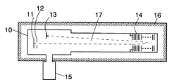
従来の飛行時間型質量分析装置の構造及び作用を図1により説明する。真空チャンバ10内の一方の端にイオン源11、イオン加速器12とイオン検出器13が、他方の端にリフレクトロン(イオン反射器)14が設けられている。イオン源としては、MALDI(Matrix Assisted Laser Desorption/Ionization)等の試料イオン化部又はLCMSなどのイオン導入部が使用される。真空チャンバ10には、高真空を達成可能なターボ分子ポンプ等の真空ポンプ15が接続されている。また、真空チャンバ10の全体は恒温槽16の中に納められている。
【0003】
イオン源11で生成されたイオンは、イオン加速器12において所定の加速電圧により運動エネルギが与えられ、リフレクトロン14に向けて飛行空間17を飛行する。イオンはリフレクトロン14における傾斜電界により反射され、飛行空間17を戻って、イオン検出器13において検出される。イオンが飛行空間17を往復するに要する時間はイオンの質量数(m/z、ただしzは電荷)に依存するため、イオン検出器13におけるイオン検出量を連続的に測定することにより、イオン源11において生成されたイオンの質量スペクトルが得られる。なお、イオン加速器とイオン検出器とを両端に配置し、イオンが飛行空間を一方向にのみ飛行した後に検出を行う一方向型のものもある。
【0004】
このような装置では、同じエネルギを与えられても、イオンの飛行時間は当然飛行距離に応じて変化する。従って、イオン加速器12、飛行空間17、リフレクトロン14、イオン検出器13等を含むイオン光学系の位置関係、特に飛行空間17の長さが変化すると、同一質量数のイオンであってもイオン検出器13に到達する時間が変化し、測定されるスペクトルの質量数軸がずれる。そこで、真空チャンバ10の全体を恒温槽16に収容し、測定時にイオン光学系の温度が一定となるように制御が行われる。
【0005】
【発明が解決しようとする課題】
高性能の飛行時間型質量分析装置に要求される時間安定性は、通常、20ppm程度であるが、飛行空間17の長さの変化による飛行時間のズレをこれ以下にしようとすると、真空チャンバ10を低熱膨張率の材料(通常、ステンレス鋼が使用される)で作製しても、その温度変化の幅を1℃程度としなければならない。一方、市販されている飛行時間型質量分析装置には、イオン飛行空間17が約1mになるものもあるため、それを内包する真空チャンバ10の全体を収容する恒温槽16は相当大きなものとならざるをえない。そのような大きな恒温槽16を1℃以下の許容幅で制御するためには、恒温槽16の熱容量を相当大きいものにし、更に、高精度の温度制御装置を設けなければならない。
【0006】
本発明はこのような課題を解決するために成されたものであり、その目的とするところは、高性能の恒温槽を設けることなく安定した質量スペクトルを得ることのできる飛行時間型質量分析装置を提供することにある。
【0007】
【課題を解決するための手段】
上記課題を解決するために成された本発明に係る飛行時間型質量分析装置は、
a)恒温槽内に保持される真空チャンバと、
b)上記真空チャンバの内部に、低熱伝導率材料から成る保持部材を介して保持され、内包するイオン飛行空間を挟んで少なくともイオン加速器とイオン検出器とが固定されたフライトチューブと、
を備えることを特徴としている。
【0008】
なお、上記「イオン飛行空間を挟んで少なくともイオン加速器とイオン検出器とが固定されたフライトチューブ」には、フライトチューブの一端にイオン加速器、他端にイオン検出器が設けられている一方向型のものの他、フライトチューブの一端にイオン加速器とイオン検出器が設けられ、他端にイオン反射器が設けられている往復型のものを含む。更に、複数のイオン反射器を介してイオンが飛行空間を往復する多重往復型のものをも含む。
【0009】
【発明の実施の形態及び効果】
イオン加速器とイオン検出器とは共にフライトチューブに固定されているため、両者間のイオン飛行空間の長さ(イオンの飛行距離)はフライトチューブの長さに依存する。このフライトチューブは、低熱伝導率材料から成る保持部材を介して真空チャンバの内部に保持されているため、真空チャンバからの空気による伝熱の影響を殆ど受けず、保持部材を介しての熱伝導の影響も殆ど受けない。従って、真空チャンバを囲う恒温槽の温度変動幅が多少大きくても、真空チャンバの内部のフライトチューブの温度変動幅は極めて小さいことが保証される。このため、イオン加速器とイオン検出器との間の距離は非常に安定したものとなり、質量分析の再現性の精度が高まる。
【0010】
本発明に係る飛行時間型質量分析装置ではこのように真空チャンバ内部の真空を断熱手段として用いているため、装置始動時にフライトチューブの温度を上げようとする際には、これが逆に昇温時間を長引かせる原因となる。そこで、本発明に係る質量分析装置では、始動時にはまず恒温槽の加熱を開始し、所定時間が経過した後に真空チャンバ内の真空引きを開始するように制御を行う制御部を設けることが望ましい。これにより、装置始動時には恒温槽の熱は真空チャンバから空気の対流を伴う伝導によりフライトチューブに与えられ、フライトチューブは比較的速やかに所定温度まで上昇することができるようになる。この「所定時間」としては、真空チャンバの真空引きが完了する時点とフライトチューブが所定の操業温度(質量分析を行うときの温度)に到達する時点がほぼ同時となるような時間に設定しておくことが望ましいが、フライトチューブが操業温度に到達したと考えられる時間の後でもよい。或いは、時間で決定するのではなく、恒温槽、真空チャンバ又はフライトチューブが、それぞれ所定の温度(前記操業温度又はそれに近い温度)になった時点で真空引きを開始するようにしてもよい。
【0011】
【実施例】
図2に本発明の一実施例である往復型飛行時間型質量分析装置の概略構成図を示す。本実施例においては、イオン加速器22、リフレクトロン24及びイオン検出器23はいずれも、真空チャンバ20内に保持されたフライトチューブ30に固定されている。往復型であるため、イオン加速器22及びイオン検出器23がフライトチューブ30の一端に設けられ、リフレクトロン24が他端に設けられている。フライトチューブ30を保持する部材31は、低熱伝導率材料(例えばセラミックや樹脂等)で作製されている。なお、イオン源(図示せず)はフライトチューブ30に固定してもよいし、フライトチューブ30とは独立に真空チャンバ20に固定してもよい。
【0012】
真空チャンバ20は恒温槽26に囲われており、恒温槽26にはヒータ32、ファン33及び温度センサ34等から成る温度調節装置が設けられている。真空チャンバ20の真空ポンプ25及び恒温槽26の温度調節装置は、コンピュータを備えた操作制御部35により制御されている。また、これとは別に、イオン加速器22及びイオン検出器23(それに、図示せぬイオン源)に接続され、試料の質量分析を行うための測定制御部36も設けられている。
【0013】
本実施例の質量分析装置が始動する際の操作制御部35の制御の内容を次に説明する。操作者が操作制御部35の始動ボタンを押すことにより、又は、所定のプログラムの実行により操作制御部35として動作しているパソコンの所定のキーを押したりマウス操作を行うと、操作制御部35はまずヒータ32に通電し、恒温槽26の温度を所定操業温度(通常、室温よりも5〜10℃高い値に設定しておく)に向けて上昇させる。それと同時に、又は所定時間後或いは温度センサ34の検出値が所定値になった時点で、ファン33を起動し、恒温槽26内の空気を攪拌する。その後、操作制御部35は温度センサ34により恒温槽26内の温度をモニタしつつヒータ32及びファン33の動作を制御することにより、オーバーシュートすることなく、装置全体が最短時間で所定の操業温度に到達するようにフィードバック制御を行う。
【0014】
このとき、真空ポンプ25は未だ起動しない。このため、真空チャンバ20内には外部と同じ圧力の空気が存在し、ヒータ32の熱は真空チャンバ20の外壁からその空気による対流を伴う伝熱により比較的速やかにフライトチューブ30に与えられる。従って、フライトチューブ30の温度は、恒温槽26からそう遅れることなく所定操業温度に到達する。
【0015】
起動時(ヒータ32への通電を開始した時点)から所定の時間が経過した時点で、操作制御部は真空ポンプ25を起動する。この「所定の時間」としては、予め実験によりフライトチューブ30が所定の操業温度に到達するまでの時間を調べておき、その値を採用する。なお、それよりもやや前でもよい。また、恒温槽26の温度が所定操業温度に到達した時点又はそれから所定時間後(フライトチューブ30への伝熱時間を考慮して)でもよい。フライトチューブ30に温度センサ34を直接取り付けることが可能である場合には、それが所定操業温度に到達した時点又はそれより少し前でもよい。
【0016】
前記のように飛行空間27の長さが1m程度の質量分析装置の場合、恒温槽26のヒータ32への通電を開始してから内部の全体が上記操業温度に到達するまでには3時間程度の時間を要する。また、飛行時間型質量分析装置では最高10-7torrの真空度で測定を行うため、その真空引きには例えば5時間程度を要する。従って、上記のような昇温後真空引きという手順で始動を行うことにより、全体として8時間程度の時間がかかる。しかし、仮に、真空引きを恒温槽26のヒータ32への通電開始と同時に行った場合には、真空チャンバ20内での空気による伝熱の効果が利用できないため、フライトチューブ30が十分に操業温度に近づくためには20時間近くかかる。従って、上記のような始動方法を採用することにより、全体の始動時間を半分以下に短縮することができる。
【0017】
操作制御部35は、温度センサ34により検出される恒温槽26内の温度が所定の値に到達し、真空計(図示せず)により検出される真空度が所定値に達した時点で、試料の質量分析を行うことができることを示す「READY」ランプを点灯する。その後は、測定制御部36の制御により、試料の質量分析が行われる。その間、操作制御部35は恒温槽26内の温度制御を行うが、この時にはフライトチューブ30は低熱伝導率材料による保持部材31及び真空により真空チャンバ20から熱的に断絶されているため、恒温槽26の温度変動は非常に長い時定数でしかフライトチューブ30の温度変動に影響を及ぼさない。これにより、フライトチューブ30の温度変動幅は恒温槽26の温度変動幅よりもかなり小さく抑えることができる。具体的には、前記のようにフライトチューブ30の温度変動幅を1℃以下に抑えるためには、恒温槽26の温度変動幅が数℃であってもよい。逆に、高性能の(温度変動幅の小さい)恒温槽26を使用することにより、フライトチューブ30の温度変動幅を更に小さく抑えることが可能となり、質量分析の精度を従来よりも高めることができるようになる。
【0018】
なお、上記実施例では理解の便のために図1と同様の往復型のもので説明を行ったが、もちろん、リフレクトロン24の位置にイオン検出器を置いた一方向型でも、本発明は全く同様に適用することができる。
【図面の簡単な説明】
【図1】 従来の往復型飛行時間型質量分析装置の概略構成図。
【図2】 本発明の一実施例である往復型飛行時間型質量分析装置の概略構成図。
【符号の説明】
10、20…真空チャンバ
11…イオン源
12、22…イオン加速部
13、23…イオン検出器
14、24…リフレクトロン(イオン反射器)
15、25…真空ポンプ
16、26…恒温槽
17、27…イオン飛行空間
30…フライトチューブ
31…フライトチューブ保持部材
32…ヒータ
33…ファン
34…温度センサ[0001]
BACKGROUND OF THE INVENTION
The present invention relates to a time-of-flight mass spectrometer.
[0002]
[Prior art]
The structure and operation of a conventional time-of-flight mass spectrometer will be described with reference to FIG. An ion source 11, an
[0003]
Ions generated by the ion source 11 are given kinetic energy by a predetermined acceleration voltage in the
[0004]
In such an apparatus, even if the same energy is given, the flight time of ions naturally changes according to the flight distance. Therefore, if the positional relationship of the ion optical system including the
[0005]
[Problems to be solved by the invention]
The time stability required for a high-performance time-of-flight mass spectrometer is usually about 20 ppm. However, if the time-of-flight deviation due to the change in the length of the
[0006]
The present invention has been made in order to solve such problems, and its object is to provide a time-of-flight mass spectrometer capable of obtaining a stable mass spectrum without providing a high-performance thermostat. Is to provide.
[0007]
[Means for Solving the Problems]
A time-of-flight mass spectrometer according to the present invention made to solve the above problems is
a) a vacuum chamber held in a thermostat;
b) A flight tube which is held inside the vacuum chamber via a holding member made of a low thermal conductivity material, and at least an ion accelerator and an ion detector are fixed across an ion flight space included therein,
It is characterized by having.
[0008]
The above-mentioned “flight tube in which at least an ion accelerator and an ion detector are fixed across an ion flight space” includes a one-way type in which an ion accelerator is provided at one end of the flight tube and an ion detector is provided at the other end. In addition to the above, the reciprocating type includes an ion accelerator and an ion detector provided at one end of the flight tube and an ion reflector provided at the other end. Further, a multiple reciprocating type in which ions reciprocate in the flight space via a plurality of ion reflectors is also included.
[0009]
BEST MODE FOR CARRYING OUT THE INVENTION
Since both the ion accelerator and the ion detector are fixed to the flight tube, the length of the ion flight space between them (the flight distance of ions) depends on the length of the flight tube. Since this flight tube is held inside the vacuum chamber via a holding member made of a low thermal conductivity material, it is hardly affected by heat transfer by air from the vacuum chamber, and heat conduction through the holding member. Is almost unaffected. Therefore, even if the temperature fluctuation range of the thermostatic chamber surrounding the vacuum chamber is somewhat large, it is guaranteed that the temperature fluctuation range of the flight tube inside the vacuum chamber is extremely small. For this reason, the distance between the ion accelerator and the ion detector becomes very stable, and the accuracy of reproducibility of mass spectrometry increases.
[0010]
In the time-of-flight mass spectrometer according to the present invention, the vacuum inside the vacuum chamber is used as a heat insulating means in this way. It will cause you to prolong. Therefore, in the mass spectrometer according to the present invention, it is desirable to provide a control unit that performs control so that heating of the thermostatic chamber is first started at the time of starting, and vacuuming in the vacuum chamber is started after a predetermined time has elapsed. Thereby, at the time of starting the apparatus, the heat of the thermostatic chamber is given to the flight tube by conduction accompanied by air convection from the vacuum chamber, and the flight tube can rise to a predetermined temperature relatively quickly. The “predetermined time” is set so that the time when the vacuum chamber is completely evacuated and the time when the flight tube reaches a predetermined operating temperature (temperature when performing mass spectrometry) are almost the same. Although it is desirable to keep it, it may be after the time when the flight tube is considered to have reached the operating temperature. Alternatively, instead of determining by time, evacuation may be started when the constant temperature bath, the vacuum chamber, or the flight tube reaches a predetermined temperature (the operation temperature or a temperature close thereto).
[0011]
【Example】
FIG. 2 shows a schematic configuration diagram of a reciprocating time-of-flight mass spectrometer which is an embodiment of the present invention. In the present embodiment, the
[0012]
The
[0013]
The contents of control of the
[0014]
At this time, the
[0015]
The operation control unit activates the
[0016]
In the case of a mass spectrometer having a
[0017]
When the temperature in the
[0018]
In the above embodiment, the reciprocating type similar to that of FIG. 1 has been described for convenience of understanding. Of course, the present invention is also applicable to a one-way type in which an ion detector is placed at the position of the
[Brief description of the drawings]
FIG. 1 is a schematic configuration diagram of a conventional reciprocating time-of-flight mass spectrometer.
FIG. 2 is a schematic configuration diagram of a reciprocating time-of-flight mass spectrometer that is an embodiment of the present invention.
[Explanation of symbols]
DESCRIPTION OF
15, 25 ... Vacuum pumps 16, 26 ...
Claims (4)
b)上記真空チャンバの内部に、低熱伝導率材料から成る保持部材を介して保持され、内包するイオン飛行空間を挟んで少なくともイオン加速器とイオン検出器とが固定されたフライトチューブと、
を備えることを特徴とする飛行時間型質量分析装置。a) a vacuum chamber held in a thermostat;
b) A flight tube which is held inside the vacuum chamber via a holding member made of a low thermal conductivity material, and at least an ion accelerator and an ion detector are fixed across an ion flight space included therein,
A time-of-flight mass spectrometer.
Priority Applications (1)
| Application Number | Priority Date | Filing Date | Title |
|---|---|---|---|
| JP2001347171A JP3659216B2 (en) | 2001-11-13 | 2001-11-13 | Time-of-flight mass spectrometer |
Applications Claiming Priority (1)
| Application Number | Priority Date | Filing Date | Title |
|---|---|---|---|
| JP2001347171A JP3659216B2 (en) | 2001-11-13 | 2001-11-13 | Time-of-flight mass spectrometer |
Publications (3)
| Publication Number | Publication Date |
|---|---|
| JP2003151488A JP2003151488A (en) | 2003-05-23 |
| JP2003151488A5 JP2003151488A5 (en) | 2005-04-07 |
| JP3659216B2 true JP3659216B2 (en) | 2005-06-15 |
Family
ID=19160217
Family Applications (1)
| Application Number | Title | Priority Date | Filing Date |
|---|---|---|---|
| JP2001347171A Expired - Lifetime JP3659216B2 (en) | 2001-11-13 | 2001-11-13 | Time-of-flight mass spectrometer |
Country Status (1)
| Country | Link |
|---|---|
| JP (1) | JP3659216B2 (en) |
Families Citing this family (9)
| Publication number | Priority date | Publication date | Assignee | Title |
|---|---|---|---|---|
| US6998607B1 (en) * | 2004-08-31 | 2006-02-14 | Thermo Finnigan Llc | Temperature compensated time-of-flight mass spectrometer |
| JP2008135192A (en) * | 2006-11-27 | 2008-06-12 | Jeol Ltd | Time-of-flight mass spectroscope |
| JP4935341B2 (en) * | 2006-12-21 | 2012-05-23 | 株式会社島津製作所 | Time-of-flight mass spectrometer |
| JP5055157B2 (en) * | 2008-02-08 | 2012-10-24 | 株式会社日立ハイテクノロジーズ | Mass spectrometer |
| JP5505224B2 (en) * | 2010-09-16 | 2014-05-28 | 株式会社島津製作所 | Time-of-flight mass spectrometer |
| EP2876434A4 (en) * | 2012-07-17 | 2016-05-04 | Snu R&Db Foundation | Method for improving mass spectrum reproducibility and quantitative analysis method using same |
| JP6795105B2 (en) * | 2017-12-04 | 2020-12-02 | 株式会社島津製作所 | Time-of-flight mass spectrometer |
| US11443934B2 (en) * | 2018-05-23 | 2022-09-13 | Shimadzu Corporation | Time-of-flight mass spectrometry device |
| WO2019229803A1 (en) * | 2018-05-28 | 2019-12-05 | 株式会社島津製作所 | Analyzer |
-
2001
- 2001-11-13 JP JP2001347171A patent/JP3659216B2/en not_active Expired - Lifetime
Also Published As
| Publication number | Publication date |
|---|---|
| JP2003151488A (en) | 2003-05-23 |
Similar Documents
| Publication | Publication Date | Title |
|---|---|---|
| JP3659216B2 (en) | Time-of-flight mass spectrometer | |
| JP4816794B2 (en) | Time-of-flight mass spectrometer | |
| JP4407486B2 (en) | Time-of-flight mass spectrometer | |
| WO2019224948A1 (en) | Time-of-flight mass spectrometer | |
| JP6658763B2 (en) | Measurement error correction method due to temperature displacement of measurement device and mass spectrometer using the method | |
| TW201734447A (en) | Method for analyzing evolved gas and evolved gas analyzing apparatus | |
| JP4935341B2 (en) | Time-of-flight mass spectrometer | |
| JPH1019867A (en) | Device for gas chromatograph and mass spectrometry | |
| JP4222005B2 (en) | Analyzer with temperature control system | |
| JP6795105B2 (en) | Time-of-flight mass spectrometer | |
| US7140231B2 (en) | Evolved gas analyzing method and apparatus | |
| KR101063089B1 (en) | Outgassing device and measuring method | |
| JPH03285246A (en) | Quadrupole mass spectrometric device | |
| JP5659286B2 (en) | Specimen stage and plasma processing apparatus provided with the same | |
| JP5055157B2 (en) | Mass spectrometer | |
| JP6536313B2 (en) | Mass spectrometer components | |
| JP6583412B2 (en) | Vacuum device and analyzer equipped with the same | |
| WO2019220552A1 (en) | Gas chromatograph mass spectrometer | |
| US11257666B2 (en) | Time-of-flight mass spectrometer | |
| US20060108350A1 (en) | Analytical device with temperature control system | |
| JP2001235374A (en) | Programmed-temperature desorption gas analyzing device | |
| CN118053730A (en) | Temperature-variable thermal analysis sample injection ionization system capable of programming temperature and mass spectrometer | |
| SU1269115A1 (en) | Constant-temperature cabinet | |
| JPS61101943A (en) | Evaporating furnace for solid sample | |
| JP2019007927A (en) | Gas chromatograph mass spectrometer |
Legal Events
| Date | Code | Title | Description |
|---|---|---|---|
| A521 | Written amendment |
Free format text: JAPANESE INTERMEDIATE CODE: A523 Effective date: 20040518 |
|
| A621 | Written request for application examination |
Free format text: JAPANESE INTERMEDIATE CODE: A621 Effective date: 20040518 |
|
| A977 | Report on retrieval |
Free format text: JAPANESE INTERMEDIATE CODE: A971007 Effective date: 20050208 |
|
| TRDD | Decision of grant or rejection written | ||
| A01 | Written decision to grant a patent or to grant a registration (utility model) |
Free format text: JAPANESE INTERMEDIATE CODE: A01 Effective date: 20050222 |
|
| A61 | First payment of annual fees (during grant procedure) |
Free format text: JAPANESE INTERMEDIATE CODE: A61 Effective date: 20050307 |
|
| R150 | Certificate of patent or registration of utility model |
Free format text: JAPANESE INTERMEDIATE CODE: R150 Ref document number: 3659216 Country of ref document: JP Free format text: JAPANESE INTERMEDIATE CODE: R150 |
|
| FPAY | Renewal fee payment (event date is renewal date of database) |
Free format text: PAYMENT UNTIL: 20080325 Year of fee payment: 3 |
|
| FPAY | Renewal fee payment (event date is renewal date of database) |
Free format text: PAYMENT UNTIL: 20090325 Year of fee payment: 4 |
|
| FPAY | Renewal fee payment (event date is renewal date of database) |
Free format text: PAYMENT UNTIL: 20100325 Year of fee payment: 5 |
|
| FPAY | Renewal fee payment (event date is renewal date of database) |
Free format text: PAYMENT UNTIL: 20100325 Year of fee payment: 5 |
|
| FPAY | Renewal fee payment (event date is renewal date of database) |
Free format text: PAYMENT UNTIL: 20110325 Year of fee payment: 6 |
|
| FPAY | Renewal fee payment (event date is renewal date of database) |
Free format text: PAYMENT UNTIL: 20110325 Year of fee payment: 6 |
|
| FPAY | Renewal fee payment (event date is renewal date of database) |
Free format text: PAYMENT UNTIL: 20120325 Year of fee payment: 7 |
|
| FPAY | Renewal fee payment (event date is renewal date of database) |
Free format text: PAYMENT UNTIL: 20120325 Year of fee payment: 7 |
|
| FPAY | Renewal fee payment (event date is renewal date of database) |
Free format text: PAYMENT UNTIL: 20130325 Year of fee payment: 8 |
|
| FPAY | Renewal fee payment (event date is renewal date of database) |
Free format text: PAYMENT UNTIL: 20140325 Year of fee payment: 9 |
|
| EXPY | Cancellation because of completion of term |