JP3659018B2 - Water-tight double tube with through hole, method for producing the same, and heat exchange type combustion tube with observation window using the water-tight double tube with through-hole - Google Patents
Water-tight double tube with through hole, method for producing the same, and heat exchange type combustion tube with observation window using the water-tight double tube with through-hole Download PDFInfo
- Publication number
- JP3659018B2 JP3659018B2 JP27281498A JP27281498A JP3659018B2 JP 3659018 B2 JP3659018 B2 JP 3659018B2 JP 27281498 A JP27281498 A JP 27281498A JP 27281498 A JP27281498 A JP 27281498A JP 3659018 B2 JP3659018 B2 JP 3659018B2
- Authority
- JP
- Japan
- Prior art keywords
- cylinder
- outer cylinder
- inner cylinder
- hole
- tube
- Prior art date
- Legal status (The legal status is an assumption and is not a legal conclusion. Google has not performed a legal analysis and makes no representation as to the accuracy of the status listed.)
- Expired - Fee Related
Links
Images


Description
【0001】
【発明の属する技術分野】
この発明は、側胴部に透孔を有する水密二重管の構造とその製造方法、および、該透孔付き水密二重管を利用した観察窓付き熱交換型燃焼筒の構成に関するものである。
【0002】
【従来の技術】
図12に、従来の透孔付き水密二重管の例として、温水ルームヒーター等の観察窓付き熱交換型燃焼筒に使用される水密二重管の構造断面図を示す。図において、101は外筒、102および103はこの外筒101に水密に突設された入口管および出口管、104は外筒101内に収納された内筒、104aおよび104bは、それぞれ、内筒104の上端部および下端部を外筒101の内周とほぼ同径になるように成形した拡管部であり、内筒104と外筒101がこの拡管部104a,104bで全周を水密に溶接されることにより、内筒104と外筒101の間の間隙105は、入口管102および出口管103と連通した水密の空間を形成する。
【0003】
また、この従来の透孔付き水密二重管には、内筒104の内側と外筒101の外側を連通する透孔管120が間隙105内を貫通して設けられ、透孔管120の両端が、それぞれ、内筒104および外筒101に溶接されることにより、間隙105の水密性が保持されるよう構成されている。
【0004】
次に、この透孔付き水密二重管を温水ルームヒーター用の観察窓付き熱交換型燃焼筒に使用した場合の動作について説明する。図12において、112はバーナーヘッド、113は内筒104の内部に構成された燃焼室であり、燃料ポンプ(図示せず)により供給された燃料がバーナーヘッド112から吐出され燃焼室113で燃焼する。一方、水密の間隙105内には入口管102から温水(図中矢印C)が供給され、間隙105内を通過する間に燃焼ガスと内筒104を介して熱交換し、加熱・昇温された温水(図中矢印D)が出口管103から送出される。また、透孔管120の外側の端部には、透明板115が固定具116によって透孔管120を塞ぐように固定されており、燃焼ガスが燃焼室113から透孔管120を通って外部に流出することを防止しながら、燃焼室113の燃焼状態を確認できる。
【0005】
【発明が解決しようとする課題】
しかしながら、上記図12に示された従来の透孔付き水密二重管は上記のような構造を有するため、内筒104および外筒101の板厚が薄い場合には、組立前に、予め内筒104と外筒101の透孔管120を挿入する部分に別々に位置を合わせながら穴加工を施し、組立時には両方の穴が同心になるように組み合せ、かつ、透孔管120を挿入してから内筒側と外筒側の両方(2個所)を溶接しなければならず、加工工程が複雑で工程数が多いため生産性が悪く、製造コストが高くなるといった問題点があった。また、薄板の場合には、透孔管120と内筒104および外筒101の溶接が難しく、溶接部の強度や水密性にばらつきが生じるといった問題点もあった。
【0006】
さらに、上記の従来の透孔付き水密二重管を観察窓付き熱交換型燃焼筒として使用した場合には、熱交換効率を上げるために、内筒104の板厚を薄くする必要があり、上記のような問題点が顕著であるばかりでなく、他の問題点として、燃焼ガスの熱によって内筒104と外筒101の間に大きな温度差が生じ、透孔管120と内筒104および外筒101の溶接部に熱応力が発生したり、また、透孔管120と内筒104との溶接部に高温の腐食性を有する燃焼ガスが直接接触する等の問題点もあった。
【0007】
この発明は、従来の透孔付き水密二重管および観察窓付き熱交換型燃焼筒の上記のような問題点を解消するためになされたもので、この発明の第1の目的は、加工・組み立てが容易で、工程数が少なく、生産性の向上と低コスト化が可能な透孔付き水密二重管とその製造方法を提供することを目的とする。
【0008】
また、この発明の第2の目的は、接合部の接合加工がしやすく、接合部の強度や水密性にばらつきの少ない透孔付き水密二重管とその製造方法を提供することを目的とする。
【0009】
さらに、この発明の第3の目的は、加工・組み立てが容易で、工程数が少なく、生産性の向上と低コスト化が可能で、しかも、燃焼時においても接合部に熱応力等が発生しにくい透孔付き水密二重管構造を有する観察窓付き熱交換型燃焼筒を提供することを目的とする。
【0010】
【課題を解決するための手段】
この発明に関わる透孔付き水密二重管は、上記の目的を達成するために、外筒と、上記外筒内に挿入された内筒とを備え、上記内筒と上記外筒とが軸方向の上部および下部で全周を水密に接合された水密二重管において、上記内筒の側胴部に上記外筒の内周に接するよう凸部を設け、上記凸部の一部を上記凸部に対応した上記外筒の側胴部とともに折曲重合して、一体の筒状のフランジ部を形成するとともに、筒状の上記フランジ部の内側に上記内筒の内側と上記外筒の外側とを連通する透孔を形成し、さらに、上記フランジ部の端部において上記内筒と上記外筒とを水密に接合するよう構成したものである。
【0011】
また、この発明に関わる透孔付き水密二重管は、外筒と、上記外筒内に挿入された内筒とを備え、上記内筒と上記外筒とが軸方向の上部および下部で全周を水密に接合された水密二重管において、上記外筒の側胴部に上記内筒の外周に接するよう凹部を設け、上記凹部の一部を上記凹部に対応した上記内筒の側胴部とともに折曲重合して、一体の筒状のフランジ部を形成するとともに、筒状の上記フランジ部の内側に上記内筒の内側と上記外筒の外側とを連通する透孔を形成し、さらに、上記フランジ部の端部において上記内筒と上記外筒とを水密に接合するよう構成したものである。
【0012】
さらに、この発明に関わる透孔付き水密二重管の製造方法は、内筒の両端部に外筒の内周に接するよう拡管部を形成するとともに、上記内筒の側胴部には上記外筒の内周に接するよう凸部を形成し、上記外筒に上記内筒を組み合せた後、上記凸部と上記凸部に対応した上記外筒の側胴部に対して同時に下穴加工を行い、続いて、バーリング加工によって上記凸部の一部と上記凸部に対応した上記外筒の側胴部を一体に折曲重合して筒状のフランジ部の形成と透孔の加工を同時に行い、最後に上記フランジ部の端部を接合するものである。
【0013】
また、この発明に関わる透孔付き水密二重管の製造方法は、外筒の両端部に内筒の外周に接するよう縮小部を形成するとともに、上記外筒の側胴部には上記内筒の外周に接するよう凹部を形成し、上記外筒に上記内筒を組み合せた後、上記凹部と上記凹部に対応した上記内筒の側胴部に対して同時に下穴加工を行い、続いて、バーリング加工によって上記凹部の一部と上記凹部に対応した上記内筒の側胴部を一体に折曲重合して筒状のフランジ部の形成と透孔の加工を同時に行い、最後に上記フランジ部の端部を接合するものである。
【0014】
また、この発明に関わる透孔付き水密二重管の製造方法は、内筒の一端部に外筒の内周に接するよう拡管部を、また、上記外筒の一端部に上記内筒の外周に接するよう縮小部を形成するとともに、上記内筒の側胴部には上記外筒の内周に接するよう凸部を形成し、上記外筒に上記内筒を組み合せた後、上記凸部と上記凸部に対応した上記外筒の側胴部に対して同時に下穴加工を行い、続いて、バーリング加工によって上記凸部の一部と上記凸部に対応した上記外筒の側胴部を一体に折曲重合して筒状のフランジ部の形成と透孔の加工を同時に行い、最後に上記フランジ部の端部を接合するものである。
【0015】
さらに、この発明に関わる透孔付き水密二重管の製造方法は、内筒の一端部に外筒の内周に接するよう拡管部を、また、上記外筒の一端部に上記内筒の外周に接するよう縮小部を形成するとともに、上記外筒の側胴部には上記内筒の外周に接するよう凹部を形成し、上記外筒に上記内筒を組み合せた後、上記凹部と上記凹部に対応した上記内筒の側胴部に対して同時に下穴加工を行い、続いて、バーリング加工によって上記凹部の一部と上記凹部に対応した上記内筒の側胴部を一体に折曲重合して筒状のフランジ部の形成と透孔の加工を同時に行い、最後に上記フランジ部の端部を接合するものである。
【0016】
また、この発明に関わる観察窓付き熱交換型燃焼筒は、外筒と、上記外筒内に挿入された内筒と、上記外筒の側胴部の外側に水密に突設された入口管および出口管とを備え、上記内筒と上記外筒とが軸方向の上部および下部で全周を水密に接合されて上記外筒と上記内筒の間に水密の間隙が形成され、上記入口管および上記出口管が上記間隙と連通するよう構成された水密二重管において、上記内筒の側胴部に上記外筒の内周に接するよう凸部を設け、上記凸部の一部を上記凸部に対応した上記外筒の側胴部とともに上記外筒の外側に折曲重合して、一体の筒状のフランジ部を上記外筒の外側に形成するとともに、筒状の上記フランジ部の内側に上記内筒の内側と上記外筒の外側とを連通する透孔を形成し、さらに、上記フランジ部の端部において上記内筒と上記外筒とを水密に接合するとともに、上記フランジ部の上記端部には上記透孔を塞ぐ透明板を設け、また、上記内筒の内側下部にはバーナーヘッドを設けたものである。
【0017】
また、この発明に関わる観察窓付き熱交換型燃焼筒は、外筒と、上記外筒内に挿入された内筒と、上記外筒の側胴部の外側に水密に突設された入口管および出口管とを備え、上記内筒と上記外筒とが軸方向の上部および下部で全周を水密に接合されて上記外筒と上記内筒の間に水密の間隙が形成され、上記入口管および上記出口管が上記間隙と連通するよう構成された水密二重管において、上記外筒の側胴部に上記内筒の外周に接するよう凹部を設け、上記凹部の一部を上記凹部に対応した上記内筒の側胴部とともに上記内筒の外側に折曲重合して、一体の筒状のフランジ部を上記内筒の外側に形成するとともに、筒状の上記フランジ部の内側に上記内筒の内側と上記外筒の外側とを連通する透孔を形成し、さらに、上記フランジ部の端部において上記内筒と上記外筒とを水密に接合するとともに、上記フランジ部の上記端部には上記透孔を塞ぐ透明板を設け、また、上記内筒の内側下部にはバーナーヘッドを設けたものである。
【0018】
【発明の実施の形態】
実施の形態1.
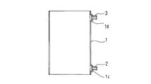
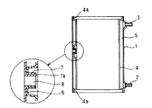
図1はこの発明の実施の形態1である透孔付き水密二重管の構造を示す断面図である。図において、1は外筒、2および3は、この外筒1の外側に水密に接合・接続された入口管および出口管、4は外筒1内に挿入された内筒、4aおよび4bは、それぞれ、内筒4の上端部と下端部を外筒1の内周に接するよう成形した拡管部であり、内筒4と外筒1は拡管部4aおよび4bで水密に接合(ロー付けないしは溶接)され、内筒4と外筒1の間に形成される間隙5は入口管2および出口管3と連通した水密の空間を構成している。
【0019】
また、この実施の形態1においては、内筒4はその側胴部の一部を外筒1の内周にほぼ接するように外側に突出、成形した凸部6を有しており、さらに、凸部6は、そのほぼ中心部分を、対応する外筒1の側胴部とともに外側に向かって一体にバーリング加工されて、外筒1の外側に筒状のフランジ部7が形成されるとともに、筒状のフランジ部7の内側には内筒4の内側から外筒1の外側に貫通する透孔8が形成され、また、フランジ部7の端部7aにおいて内筒4と外筒1が水密に接合されて、間隙5の水密性が保持されるよう構成されている。
【0020】
次に、図2〜図6を用いてこの実施の形態1の透孔付き水密二重管の具体的な製造手順について説明する。図2は、外筒1に入口管2および出口管3を接続する工程であり、まず、円筒状の外筒1の下部および上部に接続部1c、1dを形成するとともに穴開け加工がなされ、続いて、この穴の各々に入口管2および出口管3が挿入されて、接続部1c、1dと接合される。
【0021】
次に、図3に示すように、内筒4の上端部および下端部には、拡管部4aおよび4bが、また、内筒4の側胴部には、凸部6が、それぞれ、外筒1の内周にほぼ接する径になるように同時に成形される。
【0022】
続いて、図4において、内筒4が外筒1に挿入、組み合わされて二重管を構成し、外筒1と嵌合する拡管部4a、4bをシーム溶接等で全周にわたって水密に接合した後、凸部6をガイドにして、凸部6のほぼ中心部分とこの凸部6に対応する外筒1の側胴部に下穴9が同時に加工される。
【0023】
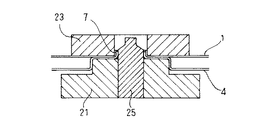
次に、凸部6のバーリング加工について図5および図6を用いて詳しく説明する。図5において、21は上方部分の外周が凸部6に嵌合し、中心に上記下穴の径より大なる径のガイド穴22を有する凸型形状のバーリング加工用ガイドであり、23は、中心にガイド穴22の径より大なる径の貫通穴24を有するバーリング加工用メス型、また、25は、上記下穴9に緩合する先端部分とテーパ状の肩部を有し、ガイド穴22内を移動可能に嵌挿されたバーリング加工用オス型である。図5に示すように、バーリング加工に先立って、内筒4の内側から凸部6にバーリング加工用ガイド21を嵌挿するとともに、外筒1の外側にはバーリング加工用メス型23を配置し、下穴9と貫通穴24およびガイド穴22が同心になるように調整される。
【0024】
続いて、図6に示すように、バーリング加工用ガイド21とバーリング加工用メス型23によって内筒4の凸部6とこの凸部6に対応した外筒1の側胴部を密着させた状態で、バーリング加工用ガイド21のガイド穴22に嵌挿させたバーリング加工用オス型25を内筒4の内側から押圧して外側に駆動すれば、凸部6の中心部分が、対応する外筒1の側胴部とともに外側に折り曲げられ(バーリング加工)、外筒1の外側に筒状のフランジ部7が形成されるとともに、同時に、筒状のフランジ部7の内側には、内筒4の内側から外筒1の外側に貫通する透孔8が形成される。
【0025】
こうして、最後に、バーリング加工によって形成されたフランジ部7の端部7aで内筒4と外筒1を水密に接合して、透孔付き水密二重管の製造工程が完了する。
【0026】
以上のように、この実施の形態1に示した透孔付き水密二重管によれば、内筒4の側胴部に外筒1の内周に接するよう凸部6を形成したため、外筒1に内筒4を組み合せた後に、内筒4と外筒1に対して同時に下穴加工を行うことが可能となって、予め内筒4と外筒1に別々に位置を合わせて下穴加工を施しておく必要がなくなり、また、凸部6を形成したことにより、内筒4と外筒1のバーリング加工が可能となってフランジ部7の形成と透孔8の加工が同時に実施でき、さらに、透孔8の加工に伴う接合個所が外筒1の外側に形成された端部7aの1個所のみとなったので、加工・組み立てが容易で、加工工程が少なくなり、生産性が向上するとともに大幅なコスト低減ができる効果がある。
【0027】
また、内筒4と外筒1が一体にバーリング加工されているためフランジ部7での内筒4と外筒1の密着性が高くなり、しかも、端部7aの接合加工が容易であるため、接合部の接合加工が均一になり、信頼性がさらに向上する効果がある。
【0028】
また、内筒4の両端部に外筒1の内周に接するよう拡管部4aおよび4bが形成されているため、両端部での内筒4と外筒1の密着性が高まって全周接合部の信頼性がさらに向上するとともに、拡管部4aおよび4bがガイドとなって内筒4を外筒1内にしっかりと固定できるため、凸部6と凸部6に対応した外筒1の側胴部の下穴加工やバーリング加工がしやすくなり、生産性が向上する効果がある。
【0029】
さらに、この実施の形態1に示した透孔付き水密二重管の製造方法によれば、外筒1に内筒4を組み合せた後に内筒4と外筒1に対して同時に下穴加工を行うとともに、バーリング加工を採用することによってフランジ部7の形成と透孔8の加工を同時に行うよう構成したため、加工・組み立てが容易で、加工工程が少なくなり、生産性が向上するとともに大幅なコスト低減ができる効果がある。また、バーリング加工によってフランジ部7での内筒4と外筒1の密着性が高くなるため、接合部の接合加工が均一になり、信頼性がさらに向上する効果がある。
【0030】
また、内筒4の両端部に外筒1の内周に接するよう拡管部4aおよび4bを形成し、両端部で内筒4と外筒1を接合した後、下穴加工やバーリング加工を行うよう構成したため、拡管部4aおよび4bがガイドとなって内筒4が外筒1内にしっかりと固定され、凸部6と凸部6に対応した外筒1の側胴部の下穴加工やバーリング加工がしやすくなって生産性が向上するとともに、両端部での内筒4と外筒1の密着性が高まって全周接合部の信頼性がさらに向上する効果がある。
【0031】
実施の形態2.
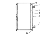
図7には、この発明の実施の形態2である透孔付き水密二重管の構造を示す。図において、1は外筒、2および3は、この外筒1の外側に水密に接合・接続された入口管および出口管、4は外筒1内に挿入された内筒、1aおよび1bは、それぞれ、外筒1の上端部と下端部を内筒4の外周に接するよう成形した縮小部であり、内筒4と外筒1は縮小部1aおよび1bで水密に接合(ロー付けないしは溶接)され、内筒4と外筒1の間に形成される間隙5は入口管2および出口管3と連通した水密の空間を構成している。
【0032】
また、この実施の形態2においては、上記の実施の形態1とは逆に、外筒1の側胴部の一部を内筒4の外周にほぼ接するように内側にへこませて凹部10を形成し、さらに、凹部10の中心部分は、この凹部10に対応する内筒4の側胴部とともに内筒4の外側に向かって一体にバーリング加工されて内筒4の外側に筒状のフランジ部7が形成されるとともに、筒状のフランジ部7の内側には内筒4の内側から外筒1の外側に貫通する透孔8が形成され、また、フランジ部7の端部7aにおいて内筒4と外筒1が水密に接合されることにより、間隙5の水密性が保持されるよう構成されている。
【0033】
なお、この実施の形態2の製造方法は、上記の実施の形態1との構造上の違いに起因して以下のようになる。(図2〜図6に示した実施の形態1の製造方法において、内筒4の凸部6の加工を外筒1の凹部10の加工に、また、内筒4の拡管部4a、4bの加工を外筒1の縮小部1a、1bの加工に置き換えればよく、以下、図面は省略する。)
【0034】
まず、円筒状の外筒1の上端部および下端部には縮小部1a、1bが、また、側胴部には凹部10が、それぞれ、内筒4の外周にほぼ接する径になるように形成されるとともに、外筒1の下部および上部には接続部1c、1dの成形と穴開け加工がなされ、続いて、この穴の各々に入口管2および出口管3が挿入されて、接続部1c、1dと接合、接続される。
【0035】
次に、内筒4が外筒1に挿入、組み合わされて二重管を構成し、内筒4と嵌合する縮小部1a,1bをシーム溶接等で全周にわたって水密に接合した後、凹部10をガイドにして、凹部10のほぼ中心部分とこの凹部10に対応する内筒4の側胴部に下穴9が同時に加工される。
【0036】
続いて、内筒4の内側に、中心に下穴9の径より大なるガイド穴22を有するバーリング加工用ガイド21を、また、外筒1の外側には、外周が凹部10に嵌合し中心にガイド穴22の径より大なる貫通穴24を有するバーリング加工用メス型23を配置し、外筒1の凹部10とこの凹部10に対応した内筒4の側胴部を密着させた状態で、ガイド穴22内に移動可能に嵌挿したバーリング加工用オス型25を内筒4の内側から押圧して外側に駆動し、凹部10とこの凹部10に対応した内筒4の側胴部を一体にバーリング加工する。
【0037】
こうして、バーリング加工によって、内筒4の外側に筒状のフランジ部7を形成するとともに、同時に、筒状のフランジ部7の内側に内筒4の内側から外筒1の外側に貫通する透孔8を形成し、最後に、フランジ部7の端部7aを水密に接合することにより、図7に示した実施の形態2の透孔付き水密二重管の製造工程が完了する。
【0038】
以上のように、この実施の形態2は実施の形態1の拡管部4a、4bおよび凸部6を、それぞれ、縮小部1a、1bおよび凹部10に置換したものであり、従って、この実施の形態2によっても、生産性の向上、コスト低減、接合部の信頼性の向上等、実施の形態1で述べたものとまったく同様の効果を得ることができる。
【0039】
なお、上記の実施の形態1および実施の形態2に示した透孔付き水密二重管の製造方法では、入口管2および出口管3を最初の工程で外筒1に接続する例を示したが、上記の工程のどの段階で接続してもよく、また、入口管2および出口管3が接続されていない水密二重管にあっても、まったく同様の効果を奏する。さらに、上記の拡管部4aおよび4bと凸部6の加工、あるいは、縮小部1aおよび1bと凹部10の加工も、必ずしも同時に行う必要はないが、同時に加工すれば工程数の削減が可能になる効果がある。
【0040】
実施の形態3.
図8には、この発明による実施の形態3である透孔付き水密二重管の構造を示す。上記の実施の形態1では、内筒4の両端部に拡管部4aおよび4bを設けて内筒4と外筒1を両端部で接合していたが、この実施の形態3では、内筒4の上端部に拡管部4aを、また、外筒1の下端部に縮小部1bを設けて内筒4と外筒1を水密に接合するよう構成している。こうして、この実施の形態3によれば、上記の実施の形態1とは内筒4と外筒1の接合部の形状が異なるだけで本質的にはまったく同じ構成および製造方法を採ることができ、実施の形態1と全く同様の効果が得られる。
【0041】
実施の形態4.
また、図9には、この発明による実施の形態4として、実施の形態2において、内筒4の一端部を拡管部とし、外筒1と接合した変形例を示す。この実施の形態4においても、上記の実施の形態3と同じく、製造方法も含めて、上記の実施の形態2と全く同様の効果が得られる。
【0042】
実施の形態5.
なお、上記の実施の形態1ないし実施の形態4では、全て、内筒4の内側から外筒1の外側へとバーリング加工して筒状のフランジ部7を形成した例を示したが、図10に示す実施の形態5のように、外筒1の外側から内筒4の内側に向けてバーリング加工し、外筒1の内側にフランジ部7を構成しても、上記の実施の形態1ないし実施の形態4と全く同様の効果が得られる。
【0043】
また、上記の実施の形態1ないし実施の形態5では、内筒4と外筒1の軸方向の長さが同じで、内筒4と外筒1の端部を揃えて接合した例を示したが、どちらかの長さが短い場合は、短い方の端部を長い方の側胴部の途中に接合してもよい。
【0044】
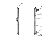
実施の形態6.
また、図11には、この発明による実施の形態6として、上記の実施の形態1の透孔付き水密二重管を温水ルームヒーターの観察窓付き熱交換型燃焼筒に適用した場合の構成を示す。図において、15は透明板であり、固定具16によりフランジ部7の端部7aに透孔8を塞ぐように固定されて観察窓を構成している。また、12は、燃料ポンプ(図示せず)から供給された燃料が吐出、燃焼するバーナヘッドであり、燃焼中、内筒4の内側の空間は燃焼室13を形成する。なお、図11において、その他の要素は図1に示した実施の形態1の透孔付き水密二重管と全く同様であり、同一符号は同一部分または相当部分を表わすため、説明を省略する。
【0045】
この実施の形態6に示された観察窓付き熱交換型燃焼筒の動作は、前述の従来例と同様に以下のようになる。すなわち、入口管2から間隙5内に流入した温水(図中矢印A)は間隙5内を通過する間に燃焼室13内の燃焼ガスと熱交換して加熱され、昇温された温水(図中矢印B)が出口管3から流出し、暖房に利用される。また、フランジ部7の端部7aに取り付けられた透明板15によって、使用者は、燃焼室13の外部に燃焼ガスを流出させることなく、透孔8を通して燃焼室13内の燃焼状態を確認することができる。
【0046】
以上のように、この実施の形態6によれば、上記の実施の形態1による透孔付き水密二重管を観察窓付き熱交換型燃焼筒として使用したため、上記の実施の形態1で得られたものと全く同様の効果が得られるとともに、加えて、この実施の形態6では、内筒4の凸部とこの凸部に対応する外筒1の側胴部を折り曲げてフランジ部7を形成したため、燃焼時の内筒4と外筒1間の温度差によって生じるひずみがこれらの折り曲げ部分で吸収され、フランジ部7の端部7aでの熱応力が減少し、接合部の信頼性がさらに向上する効果がある。また、接合個所であるフランジ部7の端部7aが外筒1の外側にあるため接合部の温度が低くなり、さらに、腐食性を有する高温の燃焼ガスに直接接触することがないため、接合部の信頼性が一層高まる効果がある。また、フランジ部7の端部7aを透明板15の受座として利用できるため、新たな受座の加工が不要となる効果もある。
【0047】
なお、この実施の形態6では、透明板15を固定具16を用いてフランジ部7に固定した例を示したが、透明板15をネジ止め等によってフランジ部7に装着してもよい。また、上記の実施の形態1の他、実施の形態2ないし実施の形態4に示した透孔付き水密二重管を観察窓付き熱交換型燃焼筒として利用しても全く同様の効果が得られる。
【0048】
【発明の効果】
この発明による透孔付き水密二重管は、以上説明したように、それぞれ、内筒または外筒に凸部または凹部を形成したため、上記内筒と上記外筒に対する同時下穴加工が可能になる他、フランジ部と透孔の同時加工が可能になり、また、上記透孔を形成する際の接合個所も上記フランジ部の端部のみに減少したことから、加工工程が少なくなり、生産性が向上するとともに大幅なコスト低減が可能な透孔付き水密二重管が得られる効果がある。また、上記フランジ部での上記内筒と上記外筒の密着性が高くなり、しかも、上記端部の接合が容易であるため、接合部の信頼性がさらに向上する効果もある。
【0049】
また、この発明による透孔付き水密二重管は、以上説明したような工程により製造されるため、下穴加工や、透孔加工とフランジ部の形成が同時に行われるため、加工工程が削減され、生産性が向上するとともに大幅なコスト低減ができる効果がある。また、バーリング加工によって上記フランジ部での上記内筒と上記外筒の密着性が高くなり、しかも、上記端部の接合が容易であるため、接合部の接合加工が均一になり、信頼性がさらに向上する効果がある。さらに、上記内筒や上記外筒の端部に、それぞれ、拡管部や縮小部を形成し、上記内筒と上記外筒をしっかり接合、固定したため、下穴加工やバーリング加工がしやすくなって生産性が向上するとともに、上記内筒と上記外筒の接合部での密着性が高まって接合部の信頼性がさらに向上する効果がある。
【0050】
さらに、この発明による観察窓付き熱交換型燃焼筒は、以上説明したように構成されているので、内筒と外筒に対する同時下穴加工が可能になり、また、フランジ部と透孔が同時に形成されるとともに、上記透孔を形成する際の接合個所も上記フランジ部の端部のみに減少したことから、工程数が少なくなり、生産性が向上するとともに大幅なコスト低減が可能な観察窓付き熱交換型燃焼筒が得られる効果がある。また、上記フランジ部での上記内筒と上記外筒の密着性が高まるとともに、上記凸部または上記凹部の折り曲げ部により上記端部の接合部の燃焼時の熱応力が緩和され、しかも、上記フランジ部を外側に形成したため、上記端部の接合部の温度が低くなるとともに接合部が燃焼ガスに直接接触しないため、接合部の信頼性がさらに向上する効果もある。
【図面の簡単な説明】
【図1】 この発明の実施の形態1の透孔付き水密二重管の構造を示す断面図。
【図2】 この発明の実施の形態1の透孔付き水密二重管の製造方法(外筒加工)を表わす断面図。
【図3】 この発明の実施の形態1の透孔付き水密二重管の製造方法(内筒加工:拡管部および凸部成形)を表わす断面図。
【図4】 この発明の実施の形態1の透孔付き水密二重管の製造方法(内外筒組み合せ、拡管部接合、下穴加工)を表わす断面図。
【図5】 この発明の実施の形態1の透孔付き水密二重管の製造方法(バーリング加工)を表わす拡大断面図。
【図6】 この発明の実施の形態1の透孔付き水密二重管の製造方法(バーリング加工)を表わす拡大断面図。
【図7】 この発明の実施の形態2の透孔付き水密二重管の構成を示す断面図。
【図8】 この発明の実施の形態3の透孔付き水密二重管の構成を示す断面図。
【図9】 この発明の実施の形態4の透孔付き水密二重管の構成を示す断面図。
【図10】 この発明の実施の形態5の透孔付き水密二重管の構成を示す断面図。
【図11】 この発明の実施の形態1の透孔付き水密二重管を観察窓付き熱交換型燃焼筒に適用した場合の構成を示す断面図。
【図12】 従来の観察窓付き熱交換型燃焼筒に用いられる透孔付き水密二重管の構造を示す断面図。
【符号の説明】
1 外筒
1a、1b 縮小部
1c、1d 接続部
2 入口管
3 出口管
4 内筒
4a、4b 拡管部
5 間隙
6 凸部
7 フランジ部
7a 端部
8 透孔
9 下穴
10 凹部
12 バーナーヘッド
13 燃焼室
15 透明板
16 固定具
21 バーリング加工用ガイド
22 ガイド穴
23 バーリング加工用メス型
24 貫通穴
25 バーリング加工用オス型[0001]
BACKGROUND OF THE INVENTION
The present invention relates to a structure of a watertight double pipe having a through hole in a side body portion, a manufacturing method thereof, and a configuration of a heat exchange type combustion cylinder with an observation window using the water tight double pipe with a through hole. .
[0002]
[Prior art]
FIG. 12 shows a structural cross-sectional view of a watertight double tube used in a heat exchange type combustion cylinder with an observation window such as a hot water room heater as an example of a conventional watertight double tube with a through hole. In the figure, 101 is an outer cylinder, 102 and 103 are water inlet-and-outlet pipes protruding from the
[0003]
In addition, in this conventional watertight double pipe with a through hole, a
[0004]
Next, the operation when this watertight double tube with a through hole is used in a heat exchange type combustion cylinder with an observation window for a hot water room heater will be described. In FIG. 12,
[0005]
[Problems to be solved by the invention]
However, since the conventional watertight double tube with a through hole shown in FIG. 12 has the above-described structure, when the
[0006]
Furthermore, when the above conventional watertight double tube with a through hole is used as a heat exchange type combustion cylinder with an observation window, it is necessary to reduce the thickness of the
[0007]
The present invention was made to solve the above-described problems of the conventional watertight double tube with a through hole and the heat exchange type combustion cylinder with an observation window. The first object of the present invention is to An object of the present invention is to provide a watertight double pipe with a through hole that can be easily assembled, has a small number of steps, and can improve productivity and reduce costs, and a method for manufacturing the same.
[0008]
A second object of the present invention is to provide a watertight double tube with a through-hole and a method for manufacturing the same, which are easy to join the joint and have little variation in strength and watertightness of the joint. .
[0009]
Furthermore, the third object of the present invention is that processing and assembly are easy, the number of steps is small, productivity can be improved and cost can be reduced, and thermal stress is generated at the joint even during combustion. An object of the present invention is to provide a heat exchange type combustion cylinder with an observation window having a water-tight double tube structure with a through hole which is difficult.
[0010]
[Means for Solving the Problems]
In order to achieve the above object, a watertight double pipe with a through hole according to the present invention includes an outer cylinder and an inner cylinder inserted into the outer cylinder, and the inner cylinder and the outer cylinder are shafts. In the watertight double pipe, the entire circumference of which is watertightly joined at the upper and lower portions in the direction, a convex portion is provided on the side barrel portion of the inner cylinder so as to contact the inner circumference of the outer cylinder, and a part of the convex portion is The side cylinder part of the outer cylinder corresponding to the convex part is bent and polymerized to form an integral cylindrical flange part, and the inner side of the inner cylinder and the outer cylinder are formed inside the cylindrical flange part. A through hole communicating with the outside is formed, and the inner cylinder and the outer cylinder are joined in a watertight manner at the end of the flange.
[0011]
The watertight double pipe with a through hole according to the present invention includes an outer cylinder and an inner cylinder inserted into the outer cylinder, and the inner cylinder and the outer cylinder are all at the upper and lower portions in the axial direction. In the watertight double pipe whose periphery is watertightly joined, a concave portion is provided in the side barrel portion of the outer cylinder so as to contact the outer circumference of the inner cylinder, and a part of the concave portion corresponds to the concave portion. Bending together with the part to form an integral cylindrical flange part, and forming a through hole communicating the inner side of the inner cylinder and the outer side of the outer cylinder inside the cylindrical flange part, Further, the inner cylinder and the outer cylinder are joined in a watertight manner at the end of the flange portion.
[0012]
Further, in the method for manufacturing a watertight double pipe with a through hole according to the present invention, a pipe expanding portion is formed at both end portions of the inner cylinder so as to be in contact with the inner periphery of the outer cylinder, and the outer cylinder is provided on the side barrel portion of the inner cylinder. A convex part is formed so as to contact the inner periphery of the cylinder, and after the inner cylinder is combined with the outer cylinder, pilot hole machining is simultaneously performed on the convex part and the side barrel part of the outer cylinder corresponding to the convex part. Next, a part of the convex part and a side body part of the outer cylinder corresponding to the convex part are bent and polymerized integrally by burring to form a cylindrical flange part and process a through hole at the same time. Finally, the end of the flange portion is joined.
[0013]
Further, in the method for manufacturing a watertight double pipe with a through hole according to the present invention, the reduced diameter portion is formed at both ends of the outer cylinder so as to be in contact with the outer periphery of the inner cylinder, and the inner cylinder is formed on the side barrel of the outer cylinder. After forming a recess so as to contact the outer periphery of the outer cylinder, combining the inner cylinder with the outer cylinder, simultaneously performing pilot hole processing on the recess and the side barrel of the inner cylinder corresponding to the recess, A part of the concave portion and the side barrel portion of the inner cylinder corresponding to the concave portion are integrally bent and polymerized by burring to simultaneously form a cylindrical flange portion and process a through hole. Finally, the flange portion Are joined.
[0014]
Further, in the method for manufacturing a watertight double pipe with a through-hole according to the present invention, a pipe expanding part is in contact with the inner circumference of the outer cylinder at one end of the inner cylinder, and the outer circumference of the inner cylinder is arranged at one end of the outer cylinder. And forming a convex portion on the side barrel of the inner cylinder so as to be in contact with the inner periphery of the outer cylinder, and combining the inner cylinder with the outer cylinder. Pilot hole processing is simultaneously performed on the side barrel portion of the outer cylinder corresponding to the convex portion, and then a part of the convex portion and the side barrel portion of the outer cylinder corresponding to the convex portion are formed by burring. They are bent together to form a cylindrical flange portion and process a through hole at the same time, and finally join the end portions of the flange portion.
[0015]
Furthermore, the manufacturing method of the watertight double pipe with a through hole according to the present invention includes a tube expanding portion at one end of the inner cylinder so as to contact the inner periphery of the outer cylinder, and an outer periphery of the inner cylinder at one end of the outer cylinder. And forming a recess in the side barrel of the outer cylinder so as to contact the outer periphery of the inner cylinder. After the inner cylinder is combined with the outer cylinder, the recess and the recess are A pilot hole is simultaneously drilled in the corresponding side barrel of the inner cylinder, and then a part of the concave portion and the side barrel of the inner cylinder corresponding to the concave portion are integrally bent and polymerized by burring. The cylindrical flange portion is formed and the through hole is simultaneously processed, and finally the end portion of the flange portion is joined.
[0016]
Further, the heat exchange type combustion cylinder with an observation window according to the present invention includes an outer cylinder, an inner cylinder inserted into the outer cylinder, and an inlet pipe protruding in a watertight manner on the outer side of a side body portion of the outer cylinder. And an outlet pipe, and the inner cylinder and the outer cylinder are joined together in a watertight manner at the upper and lower portions in the axial direction to form a watertight gap between the outer cylinder and the inner cylinder, and the inlet In the watertight double pipe configured such that the pipe and the outlet pipe communicate with the gap, a convex portion is provided on the side barrel portion of the inner cylinder so as to contact the inner periphery of the outer cylinder, and a part of the convex portion is provided. A cylindrical flange portion is formed on the outer side of the outer cylinder by bending and superposing on the outer side of the outer cylinder together with the side barrel portion of the outer cylinder corresponding to the convex portion, and the cylindrical flange portion A through hole is formed on the inner side of the inner cylinder and the outer side of the outer cylinder. In addition, the inner cylinder and the outer cylinder are joined in a watertight manner, a transparent plate that closes the through hole is provided at the end of the flange portion, and a burner head is provided at the inner lower portion of the inner cylinder. Is.
[0017]
Further, the heat exchange type combustion cylinder with an observation window according to the present invention includes an outer cylinder, an inner cylinder inserted into the outer cylinder, and an inlet pipe protruding in a watertight manner on the outer side of a side body portion of the outer cylinder. And an outlet pipe, and the inner cylinder and the outer cylinder are joined together in a watertight manner at the upper and lower portions in the axial direction to form a watertight gap between the outer cylinder and the inner cylinder, and the inlet In the watertight double pipe configured so that the pipe and the outlet pipe communicate with the gap, a concave portion is provided in a side body portion of the outer cylinder so as to contact an outer periphery of the inner cylinder, and a part of the concave portion is provided in the concave section. The inner cylinder is bent and polymerized together with the corresponding side cylinder of the inner cylinder to form an integral cylindrical flange on the outer side of the inner cylinder, and the inner side of the cylindrical flange is A through hole is formed to communicate the inner side of the inner cylinder and the outer side of the outer cylinder, and further, at the end of the flange part In addition, the inner cylinder and the outer cylinder are joined in a watertight manner, a transparent plate that closes the through hole is provided at the end of the flange portion, and a burner head is provided at the inner lower portion of the inner cylinder. Is.
[0018]
DETAILED DESCRIPTION OF THE INVENTION
1 is a cross-sectional view showing the structure of a watertight double pipe with a through hole according to
[0019]
Moreover, in this
[0020]
Next, a specific manufacturing procedure of the watertight double pipe with a through hole according to the first embodiment will be described with reference to FIGS. FIG. 2 is a process of connecting the
[0021]
Next, as shown in FIG. 3, the expanded
[0022]
Subsequently, in FIG. 4, the
[0023]
Next, the burring process of the
[0024]
Subsequently, as shown in FIG. 6, a state in which the
[0025]
Thus, finally, the
[0026]
As described above, according to the watertight double tube with a through-hole shown in the first embodiment, the
[0027]
Further, since the
[0028]
In addition, since the expanded
[0029]
Furthermore, according to the method for manufacturing a watertight double pipe with a through hole shown in the first embodiment, after the
[0030]
In addition,
[0031]
FIG. 7 shows the structure of a watertight double pipe with a through hole, which is
[0032]
In the second embodiment, contrary to the first embodiment, a part of the side barrel portion of the
[0033]
The manufacturing method of the second embodiment is as follows due to the structural difference from the first embodiment. (In the manufacturing method of
[0034]
First, the reduced
[0035]
Next, the
[0036]
Subsequently, a burring
[0037]
In this way, the
[0038]
As described above, the second embodiment is obtained by replacing the expanded
[0039]
In addition, in the manufacturing method of the watertight double pipe with a through-hole shown in said
[0040]
FIG. 8 shows the structure of a watertight double pipe with a through hole according to
[0041]
FIG. 9 shows a modification in which one end portion of the
[0042]
In the first to fourth embodiments described above, an example is shown in which the
[0043]
In the first to fifth embodiments, the
[0044]
Further, FIG. 11 shows, as
[0045]
The operation of the heat exchange type combustion cylinder with the observation window shown in the sixth embodiment is as follows as in the above-described conventional example. That is, the hot water flowing into the
[0046]
As described above, according to the sixth embodiment, since the watertight double tube with a through hole according to the first embodiment is used as a heat exchange type combustion cylinder with an observation window, it is obtained in the first embodiment. In the sixth embodiment, the
[0047]
In the sixth embodiment, an example in which the
[0048]
【The invention's effect】
As described above, the water-tight double pipe with a through hole according to the present invention has a convex portion or a concave portion formed in the inner cylinder or the outer cylinder, respectively, so that simultaneous pilot hole processing for the inner cylinder and the outer cylinder becomes possible. In addition, simultaneous processing of the flange portion and the through hole is possible, and the joint portion when forming the through hole is reduced only to the end portion of the flange portion, so that the processing steps are reduced and the productivity is reduced. There is an effect that a watertight double pipe with a through-hole capable of being improved and greatly reduced in cost can be obtained. Moreover, since the adhesiveness between the inner cylinder and the outer cylinder at the flange portion is increased and the end portions are easily joined, there is an effect of further improving the reliability of the joined portion.
[0049]
Further, since the watertight double pipe with a through hole according to the present invention is manufactured by the process as described above, the preparation process is performed and the through hole processing and the formation of the flange portion are performed at the same time. As a result, productivity is improved and cost can be significantly reduced. In addition, the burring process increases the adhesion between the inner cylinder and the outer cylinder at the flange part, and since the end part can be easily joined, the joining process of the joined part becomes uniform and the reliability is improved. There is a further improvement effect. Furthermore, the tube expansion part and the reduction part are formed at the end of the inner cylinder and the outer cylinder, respectively, and the inner cylinder and the outer cylinder are firmly joined and fixed. While improving productivity, the adhesiveness in the junction part of the said inner cylinder and the said outer cylinder increases, and there exists an effect which further improves the reliability of a junction part.
[0050]
Furthermore, since the heat exchange type combustion cylinder with an observation window according to the present invention is configured as described above, it is possible to simultaneously prepare a pilot hole for the inner cylinder and the outer cylinder, and the flange portion and the through hole are simultaneously provided. In addition to the formation of the through-holes, the number of joints has been reduced to the end of the flange, reducing the number of processes, improving productivity, and significantly reducing costs. There is an effect that an attached heat exchange type combustion cylinder is obtained. In addition, adhesion between the inner cylinder and the outer cylinder at the flange portion is enhanced, and thermal stress at the time of combustion at the joint portion of the end portion is relieved by the bent portion of the convex portion or the concave portion, and Since the flange portion is formed on the outside, the temperature of the joint portion at the end portion is lowered, and the joint portion does not directly contact the combustion gas, so that the reliability of the joint portion is further improved.
[Brief description of the drawings]
FIG. 1 is a cross-sectional view showing the structure of a watertight double tube with a through hole according to
FIG. 2 is a cross-sectional view showing a method (outer cylinder processing) for manufacturing a watertight double pipe with a through-hole according to
FIG. 3 is a cross-sectional view illustrating a method for manufacturing a watertight double tube with a through hole according to
FIG. 4 is a cross-sectional view illustrating a method for manufacturing a watertight double pipe with a through hole according to
FIG. 5 is an enlarged cross-sectional view showing a method (burring process) for manufacturing a watertight double tube with a through hole according to
6 is an enlarged cross-sectional view showing a method (burring process) for manufacturing a watertight double tube with a through hole according to
FIG. 7 is a cross-sectional view showing a configuration of a watertight double pipe with a through hole according to a second embodiment of the present invention.
FIG. 8 is a cross-sectional view showing a configuration of a watertight double pipe with a through hole according to a third embodiment of the present invention.
FIG. 9 is a cross-sectional view showing a configuration of a watertight double pipe with a through hole according to a fourth embodiment of the present invention.
FIG. 10 is a sectional view showing the structure of a watertight double pipe with a through hole according to a fifth embodiment of the present invention.
FIG. 11 is a cross-sectional view showing a configuration when the watertight double tube with a through hole according to the first embodiment of the present invention is applied to a heat exchange type combustion cylinder with an observation window.
FIG. 12 is a cross-sectional view showing the structure of a watertight double tube with a through hole used in a conventional heat exchange type combustion cylinder with an observation window.
[Explanation of symbols]
1 outer cylinder
1a, 1b Reduction part
1c, 1d connection
2 inlet pipe
3 outlet pipe
4 inner cylinder
4a, 4b Expanded part
5 gap
6 Convex
7 Flange
7a end
8 Through hole
9 Pilot hole
10 recess
12 Burner head
13 Combustion chamber
15 Transparent plate
16 Fixture
21 Burling guide
22 Guide hole
23 Female type for burring
24 Through hole
25 Male type for burring
Claims (8)
(a)外筒の内周にほぼ接するよう内筒の上端部および下端部に拡管部を形成する工程
(b)外筒の内周にほぼ接するよう内筒の側胴部外側に凸部を形成する工程
(c)上記外筒内に上記内筒を挿入し、上記拡管部と上記外筒を全周にわたって水密に接合する工程
(d)上記凸部および上記凸部に対応する上記外筒の側胴部に、上記内筒および上記外筒に貫通する下穴を一体に加工する工程
(e)上記下穴をガイドとして、上記凸部の一部を上記凸部に対応する上記外筒の側胴部とともに一体にバーリング加工し、一体の筒状のフランジ部を形成するとともに、同時に、筒状の上記フランジ部の内側に上記内筒の内側と上記外筒の外側とを連通する透孔を形成する工程。
(f)上記内筒と上記外筒を、バーリング加工によって形成された上記フランジ部の端部において水密に接合する工程。The manufacturing method of the watertight double pipe with a through-hole of Claim 1 provided with the following processes.
(A) A step of forming a tube expansion portion at the upper end portion and the lower end portion of the inner cylinder so as to be substantially in contact with the inner periphery of the outer cylinder. (B) Protruding portions on the outer side of the side barrel portion of the inner cylinder so as to be substantially in contact with the inner periphery of the outer cylinder. Forming step (c) inserting the inner cylinder into the outer cylinder, and joining the expanded pipe part and the outer cylinder in a water-tight manner over the entire circumference (d) the convex part and the outer cylinder corresponding to the convex part A step of integrally processing a pilot hole penetrating the inner cylinder and the outer cylinder in the side barrel portion of the outer cylinder. (E) The outer cylinder corresponding to the convex portion by using the pilot hole as a guide. Burring together with the side barrel portion to form an integral cylindrical flange portion, and at the same time, the inner side of the inner cylinder and the outer side of the outer cylinder communicate with the inner side of the cylindrical flange portion. Forming a hole;
(F) A step of joining the inner cylinder and the outer cylinder in a water-tight manner at an end of the flange portion formed by burring.
(a)内筒の外周にほぼ接するよう外筒の上端部および下端部に縮小部を形成する工程
(b)内筒の外周にほぼ接するよう外筒の側胴部に凹部を形成する工程
(c)上記外筒内に上記内筒を挿入し、上記縮小部と上記内筒を全周にわたって水密に接合する工程
(d)上記凹部および上記凹部に対応する上記内筒の側胴部に、上記内筒および上記外筒に貫通する下穴を一体に加工する工程
(e)上記下穴をガイドとして、上記凹部の一部を上記凹部に対応する上記内筒の側胴部とともに一体にバーリング加工し、一体の筒状のフランジ部を形成するとともに、同時に、筒状の上記フランジ部の内側に上記内筒の内側と上記外筒の外側とを連通する透孔を形成する工程。
(f)上記内筒と上記外筒を、バーリング加工によって形成された上記フランジ部の端部において水密に接合する工程。The manufacturing method of the watertight double pipe with a through-hole of Claim 2 provided with the following processes.
(A) A step of forming a reduced portion at the upper end and lower end of the outer cylinder so as to substantially contact the outer periphery of the inner cylinder (b) A step of forming a recess in the side barrel of the outer cylinder so as to substantially contact the outer periphery of the inner cylinder ( c) Inserting the inner cylinder into the outer cylinder and watertightly joining the reduced portion and the inner cylinder over the entire circumference (d) In the concave portion and the side barrel portion of the inner cylinder corresponding to the concave portion, Step of integrally processing pilot holes penetrating through the inner cylinder and the outer cylinder (e) Using the pilot hole as a guide, part of the concave portion is integrated with the side barrel portion of the inner cylinder corresponding to the concave portion. Processing to form an integral cylindrical flange portion, and at the same time, forming a through hole communicating the inner side of the inner cylinder and the outer side of the outer cylinder inside the cylindrical flange portion.
(F) A step of joining the inner cylinder and the outer cylinder in a water-tight manner at an end of the flange portion formed by burring.
(a)外筒の内周にほぼ接するよう内筒の一端部に拡管部を形成する工程
(b)外筒の内周にほぼ接するよう内筒の側胴部外側に凸部を形成する工程
(c)内筒の外周にほぼ接するよう外筒の一端部に縮小部を形成する工程
(d)上記外筒内に上記内筒を挿入し、それぞれ、上記拡管部と上記外筒を、また、上記縮小部と上記内筒を全周にわたって水密に接合する工程
(e)上記凸部および上記凸部に対応する上記外筒の側胴部に、上記内筒および上記外筒に貫通する下穴を一体に加工する工程
(f)上記下穴をガイドとして、上記凸部の一部を上記凸部に対応する上記外筒の側胴部とともに一体にバーリング加工し、一体の筒状のフランジ部を形成するとともに、同時に、筒状の上記フランジ部の内側に上記内筒の内側と上記外筒の外側とを連通する透孔を形成する工程。
(g)上記内筒と上記外筒を、バーリング加工によって形成された上記フランジ部の端部において水密に接合する工程。The manufacturing method of the watertight double pipe with a through-hole of Claim 1 provided with the following processes.
(A) A step of forming a tube expansion portion at one end portion of the inner cylinder so as to substantially contact the inner periphery of the outer tube (b) A step of forming a convex portion outside the side barrel portion of the inner cylinder so as to substantially contact the inner periphery of the outer cylinder. (C) a step of forming a reduced portion at one end of the outer cylinder so as to substantially contact the outer periphery of the inner cylinder; (d) inserting the inner cylinder into the outer cylinder, and connecting the expanded pipe section and the outer cylinder, respectively, A step of water-tightly joining the reduced portion and the inner cylinder over the entire circumference (e) a lower body penetrating the inner cylinder and the outer cylinder in the side barrel of the outer cylinder corresponding to the convex part and the convex part (F) Using the pilot hole as a guide, a part of the convex portion is integrally burred together with the side barrel portion of the outer cylinder corresponding to the convex portion, and an integral cylindrical flange is formed. At the same time, the inner side of the inner cylinder and the outer side of the outer cylinder inside the cylindrical flange part Forming a through hole that communicates.
(G) A step of joining the inner cylinder and the outer cylinder in a watertight manner at an end of the flange portion formed by burring.
(a)内筒の外周にほぼ接するよう外筒の一端部に縮小部を形成する工程
(b)内筒の外周にほぼ接するよう外筒の側胴部に凹部を形成する工程
(c)外筒の内周にほぼ接するよう内筒の一端部に拡管部を形成する工程
(d)上記外筒内に上記内筒を挿入し、それぞれ、上記拡管部と上記外筒を、また、上記縮小部と上記内筒を全周にわたって水密に接合する工程
(e)上記凹部および上記凹部に対応する上記内筒の側胴部に、上記内筒および上記外筒に貫通する下穴を一体に加工する工程
(f)上記下穴をガイドとして、上記凹部の一部を上記凹部に対応する上記内筒の側胴部とともに一体にバーリング加工し、一体の筒状のフランジ部を形成するとともに、同時に、筒状の上記フランジ部の内側に上記内筒の内側と上記外筒の外側とを連通する透孔を形成する工程。
(g)上記内筒と上記外筒を、バーリング加工によって形成された上記フランジ部の端部において水密に接合する工程。The manufacturing method of the watertight double pipe with a through-hole of Claim 2 provided with the following processes.
(A) a step of forming a reduced portion at one end of the outer cylinder so as to be substantially in contact with the outer periphery of the inner cylinder; (b) a step of forming a recess in the side barrel of the outer cylinder so as to be substantially in contact with the outer periphery of the inner cylinder; A step of forming a tube expansion portion at one end of the inner tube so as to substantially contact the inner periphery of the tube; (d) inserting the inner tube into the outer tube, and respectively reducing the tube expansion portion and the outer tube; A step of watertightly joining the inner portion and the inner cylinder over the entire circumference (e) integrally processing a pilot hole penetrating the inner cylinder and the outer cylinder in the concave portion and the side barrel portion of the inner cylinder corresponding to the concave portion (F) Using the pilot hole as a guide, part of the recess is integrally burred together with the side barrel portion of the inner cylinder corresponding to the recess to form an integral cylindrical flange portion, and at the same time The inner side of the inner cylinder and the outer side of the outer cylinder are connected to the inside of the cylindrical flange portion. Forming a through hole to be.
(G) A step of joining the inner cylinder and the outer cylinder in a watertight manner at an end of the flange portion formed by burring.
Priority Applications (1)
| Application Number | Priority Date | Filing Date | Title |
|---|---|---|---|
| JP27281498A JP3659018B2 (en) | 1998-09-28 | 1998-09-28 | Water-tight double tube with through hole, method for producing the same, and heat exchange type combustion tube with observation window using the water-tight double tube with through-hole |
Applications Claiming Priority (1)
| Application Number | Priority Date | Filing Date | Title |
|---|---|---|---|
| JP27281498A JP3659018B2 (en) | 1998-09-28 | 1998-09-28 | Water-tight double tube with through hole, method for producing the same, and heat exchange type combustion tube with observation window using the water-tight double tube with through-hole |
Publications (2)
| Publication Number | Publication Date |
|---|---|
| JP2000104996A JP2000104996A (en) | 2000-04-11 |
| JP3659018B2 true JP3659018B2 (en) | 2005-06-15 |
Family
ID=17519133
Family Applications (1)
| Application Number | Title | Priority Date | Filing Date |
|---|---|---|---|
| JP27281498A Expired - Fee Related JP3659018B2 (en) | 1998-09-28 | 1998-09-28 | Water-tight double tube with through hole, method for producing the same, and heat exchange type combustion tube with observation window using the water-tight double tube with through-hole |
Country Status (1)
| Country | Link |
|---|---|
| JP (1) | JP3659018B2 (en) |
Families Citing this family (2)
| Publication number | Priority date | Publication date | Assignee | Title |
|---|---|---|---|---|
| JP4039365B2 (en) * | 2003-12-26 | 2008-01-30 | 三菱電機株式会社 | Combustion device |
| JP3993594B2 (en) * | 2004-09-27 | 2007-10-17 | 株式会社ケーヒン | Electromagnetic fuel injection valve |
-
1998
- 1998-09-28 JP JP27281498A patent/JP3659018B2/en not_active Expired - Fee Related
Also Published As
| Publication number | Publication date |
|---|---|
| JP2000104996A (en) | 2000-04-11 |
Similar Documents
| Publication | Publication Date | Title |
|---|---|---|
| JP2736508B2 (en) | Port flange connection of manifold with air gap | |
| JP2005121350A (en) | Heat exchanger and method for manufacturing it | |
| JP2004116334A (en) | Fuel rail, main pipe for fuel rail and their manufacturing method | |
| CN111730331B (en) | Heat exchanger and method for manufacturing the same | |
| NO801669L (en) | DEVICE FOR EXHAUST ENGINE FOR COMBUSTION ENGINES | |
| US6038769A (en) | Method for manufacturing an air-gap-insulated exhaust manifold | |
| JP4287125B2 (en) | Piping connection structure to flange | |
| CA2451363C (en) | A method for producing head element for heaters and head element obtained by this method | |
| KR20110139180A (en) | Cooling plate | |
| US20180292138A1 (en) | Manifold for a heat exchanger | |
| JPH0253151B2 (en) | ||
| JP3659018B2 (en) | Water-tight double tube with through hole, method for producing the same, and heat exchange type combustion tube with observation window using the water-tight double tube with through-hole | |
| JPH09105327A (en) | Exhaust gas conduit for internal combusion engine | |
| JP2007237294A (en) | Method of manufacturing combustion chamber | |
| JP3818977B2 (en) | Pipe joint structure | |
| JP2002364934A (en) | Method for manufacturing double walled header pipe | |
| JPH0886577A (en) | Heat exchanger | |
| JPS61108482A (en) | Joining method of tube plate and heat exchanger tube | |
| US20070251684A1 (en) | Watertube and Method of Making and Assembling Same within a Boiler or Heat Exchanger | |
| JP4037761B2 (en) | Lining device for plate heat exchanger | |
| JPH09133491A (en) | Manufacture of heat exchanger | |
| JP2000249438A (en) | Cylindrical heat exchanger | |
| KR101180476B1 (en) | A manufacturing method of the tube connector assembley | |
| JP2004069210A (en) | Multi-pipe type heat exchanger and manufacturing method thereof | |
| KR100681340B1 (en) | Pipe connecting structure of boiler |
Legal Events
| Date | Code | Title | Description |
|---|---|---|---|
| RD01 | Notification of change of attorney |
Free format text: JAPANESE INTERMEDIATE CODE: A7421 Effective date: 20040622 |
|
| TRDD | Decision of grant or rejection written | ||
| A01 | Written decision to grant a patent or to grant a registration (utility model) |
Free format text: JAPANESE INTERMEDIATE CODE: A01 Effective date: 20050222 |
|
| A61 | First payment of annual fees (during grant procedure) |
Free format text: JAPANESE INTERMEDIATE CODE: A61 Effective date: 20050307 |
|
| FPAY | Renewal fee payment (event date is renewal date of database) |
Free format text: PAYMENT UNTIL: 20080325 Year of fee payment: 3 |
|
| FPAY | Renewal fee payment (event date is renewal date of database) |
Free format text: PAYMENT UNTIL: 20090325 Year of fee payment: 4 |
|
| LAPS | Cancellation because of no payment of annual fees |