JP3658914B2 - Steering device for work vehicle - Google Patents
Steering device for work vehicle Download PDFInfo
- Publication number
- JP3658914B2 JP3658914B2 JP4800197A JP4800197A JP3658914B2 JP 3658914 B2 JP3658914 B2 JP 3658914B2 JP 4800197 A JP4800197 A JP 4800197A JP 4800197 A JP4800197 A JP 4800197A JP 3658914 B2 JP3658914 B2 JP 3658914B2
- Authority
- JP
- Japan
- Prior art keywords
- steering
- tractor
- amount
- work
- brake
- Prior art date
- Legal status (The legal status is an assumption and is not a legal conclusion. Google has not performed a legal analysis and makes no representation as to the accuracy of the status listed.)
- Expired - Lifetime
Links
Images


Description
【0001】
【発明の属する技術分野】
この発明は、トラクタや田植機の作業車両の操向装置の構成に関する。
【0002】
【従来の技術、及び課題】
従来、作業車両には、特開平8−156812号公報に示されているトラクタのように、耕耘作業での枕時旋回にステアリング操作を軽減するため、ステアリングハンドルの操作量に対して前輪の切れ角度を変更可能な操向装置を設けたものが知られている。
【0003】
【発明が解決しようとする課題】
しかしながら、前記公報に示されたものは、この操向装置の作動量をモード切替スイッチで切り替える構成であるので、圃場の形状によって小回り旋回と、大回り旋回とが繰り返し必要とされる場合は、旋回のたびにモード切替スイッチを切り替えて、前輪の操向量を大きくするか、或いは通常通りとするかを切り替える必要があった。このためトラクタの操作性を損なうものであった。
【0004】
【課題を解決するための手段】
この発明は、以上のような課題を解消するために、次のような技術的手段を講じた。即ち、左右駆動輪1,1をそれぞれ独立して制動するブレーキペダル2,2と、ステアリングハンドル3の操作量に対する操向輪4,4の作動量を変更可能な操向装置5とを有する作業車両において、前記ブレーキペダル2,2の踏み込み操作を検出する検出手段6と、作業機20の高さを検出する手段19s(23s)を設け、このブレーキペダル2の踏み込み操作が検出され且つ作業機20の高さが一定以上である時に、前記操向装置5によりステアリングハンドル3の操作量に対する操向輪4,4の操向量を増大可能に構成すると共に、前記操向量を増大させている状態を前記作業機20の下降操作に連動して解除する構成としたことを特徴とする作業車両の操向装置とした。
【0005】
【発明の効果】
これにより、オペレータが小回り旋回を行うことをブレーキペダル2,2の踏み込み操作にて判別し、この踏み込み操作が検出され且つ作業機20の高さが一定以上であるときにだけステアリングハンドル3の操作量に対して操向輪4,4の切れ角度を増大可能にしたので、大回り旋回時や旋回終了後の条合わせなど操向輪4,4の操向量が増大すると具合の悪いときには、通常の操向操作が可能になり作業車両の操作性が向上する。
また、この操向量を増大させている状態を作業機20の下降操作を検出して解除する構成としているので、例えばトラクタ等で旋回後に作業機20を上昇したまま畦際まで後進して、この畦際まで操向する時でも操向輪4、4を少ないステアリング操作で操向することができ、同装置を圃場作業に適した状態で作動することができる。
【0006】
【発明の実施の形態】
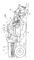
以下、この発明の実施の形態を作業車両である農用トラクタ(以下、トラクタ10)について説明する。トラクタ10の全体構成について説明する。
トラクタ10には、機体前部のボンネット11の内部にエンジン12を設け、このエンジン12からクラッチハウジング、ミッションケース13、及びリアミッションケース14等を一体に連結して設け車体の主枠を構成している。また、エンジン12の下方左右には操向輪である前輪4,4を設け、リヤミッションケース13の左右側方には駆動輪である後輪1,1を設けている。前輪1,1には、この操向角度を検出する前輪切角センサ9を設け、このトラクタ10の操向を検出する構成となっている。
【0007】
前記ボンネット11の後面には、ハンドルポスト15を設け、この側方に前後進切替レバー16を設け、同ポスト15の上部にステアリングハンドル3を突出して設けている。そして、このステアリングハンドル3の回転操作により後述する操向装置であるパワーステアリング装置5を介して前記前輪4,4を操向する構成となっている。この前後進切替レバー16の回動基部には、前方へ押し込んだときにオンして後述する切替制御弁51を切り替える前進スイッチ16Fと、後方へ引き込んだときにオンして同制御弁51を切り替える後進スイッチ16Rとを設けている。また、ハンドルポスト15の下方には、左右夫々の後輪1,1を制動するブレーキペダル2,2を設けている。ブレーキペダル2,2の左右夫々の回動基部には、この踏み込み操作を検出する手段であるブレーキスイッチ6,6を設け、この踏み込み時にオンする構成となっている。
【0008】
トラクタ10の操縦席17の近傍について説明すると、この操縦席17の側方には、旋回時の前輪4,4の作動量を変更する制御を入り切りする制御スイッチ8と、走行用変速レバー18と、作業機20の操作部であるポジションレバー19を設けている。また、後述する作業機20を駆動するPTO軸21の回転を入り切りするPTO入切スイッチ22と設けている。前記変速レバー18の回動基部には、ポテンショメータ18sを設け、オペレータのレバー操作を操縦席17の下方に設けた制御部であるコントローラ7へ入力し、この変速操作に応じてミッションケース13,14内の変速装置33を切り替える構成となっている。また、前記ポジションレバー19の回動基部にも、ポテンショメータ19sを設け、コントローラ7は、同レバー19の操作角度を検出し、これに応じて後述するリフトアーム角センサ23sの設定角度が一致するように作業機昇降用の比例圧力制御弁のソレノイド66s、67sを励磁して後述するシリンダ24を駆動する構成となっている。
【0009】
トラクタ10の後部の構成について説明する。前記リヤミッションケース13の後上部にはシリンダーケース25を設けている。このシリンダーケース25には作業機昇降シリンダ24を内蔵し、この昇降シリンダ24のピストン伸縮によりケース25の左右に支持したリフトアーム26,26を上下回動する構成となっている。そして、このリフトアーム26の回動基部には、作業機位置検出手段であるリフトアーム角センサ23sを設け、作業機20の昇降位置を間接的に検出する構成となっている。また、リヤミッションケース14の後部にはトップリンク27と左右ロアリンク28,28とからなる3点リンク機構を設け,この後端部に作業機20を連結可能に構成している。
【0010】
図例の作業機20は、ロータリ作業機であって、トラクタ10のエンジン11の回転動力をリヤミッションケース14背面のPTO軸21より取り出し、伝達軸29を介して作業機20側へ伝達し、この作業機20側の伝導機構を介して複数の耕耘爪33…を有する耕耘軸31を回転し、圃場を耕起する構成となっている。
【0011】
トラクタ10の後輪1,1を制動するブレーキ装置について図3に基づいて説明する。前記リヤミッションケース14内部に設けた後輪1,1を駆動する駆動軸36には、左右ぞれぞれブレーキディスク37…を設けている。このブレーキディスク37…は、前記ブレーキペダル2とリンク機構を介して左右独立して接続され、このブレーキペダル2の踏み込み操作によりディスク同士が圧着する構成となっている。これにより、圃場での作業では、トラクタ10の後輪を片側だけ制動可能になり隣接旋回を容易にしている。尚、トラクタ10のエンジン12の回転動力は、主クラッチ32、前後進切替装置34、主変速装置33A、副変速装置33Bと伝達し、この副変速装置33Bで出力された回転動力を、後輪デフ装置39と、前輪駆動伝達装置60へと分岐している。
【0012】
トラクタ10のパワーステアリング装置5について図4に基づいて説明する。パワーステアリング装置5は、ステアリングハンドル3の回転操作をステアリング軸40等を介して操舵ユニット41に入力している。そして、このステアリング軸40の回転に応じてジロータ42が回転され、ポンプ43の油圧力が操舵ユニット41から出力される構成となっている。この操舵ユニット41と前輪操向用の油圧シリンダ44間の油路には、この圧油の一部をタンク45へ逃がす絞り46,46を有する切替制御弁47と、この切替制御弁47の送り出した圧油の逆流を止めるチェック弁48を設けている。この切替制御弁47は、通常時には前記絞り46,46を有する油室49側に位置し、コントローラ7からの切替指令により絞り46,46を設けない油室50へ切り替わり、全流量を前記シリンダ44へ送り込む構成となっている。即ち、切替制御弁47が絞り46,46の設けてない油圧室50に切り替わっているときには、通常時と比較してステアリングハンドル3の操作量に対して前輪4,4の操向量を増大することができる。
【0013】
前記コントローラ7は、図5に示されるように各種センサやスイッチの情報を処理するCPUや、この情報を一時記憶するRAMや、この制御プログラムを設定しているROM等を有する構成となっている。そして、入力部には、前記制御スイッチ8と、前記前進スイッチ16F、後進スイッチ16Rと、前輪切角センサ9と、左右ブレーキスイッチ6,6と、変速レバー18のポテンショメータ18sと、ポジションレバー19のポテンショメータ19sと、PTO入切スイッチ22と、リフトアーム角センサ23とを接続して設けている。また、出力部には、前進用油圧クラッチ52F,52Rの前進、及び後進用のソレノイド51F,51Rと、前記PTO入切スイッチ22に応じて油路を段階的に開放する切替制御弁59のソレノイド59a、及び59b、昇降シリンダ24のピストンを伸縮する比例圧力制御弁のソレノイド66s,67sと、前記操向用シリンダ44への圧油量を切り替える切替制御弁47のソレノイド47sを接続して設けている。
【0014】
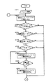
以上のように構成されたトラクタ10の操向装置の作用ついて、図1のフローチャートに基づいて説明する。
【0015】
最初に、トラクタ10の電源系統を「入」にしてエンジン12を始動すると共に(STEP1)、コントローラ7は、前記制御スイッチ8等のスイッチやセンサの設定状態、接続状態を読み込む(STEP2)。次に左右どちらか一方のブレーキスイッチ6がオンされたかどうがが判定される(STEP3)。ここでYESであれば、続いてリフトアーム角センサ23sにより作業機20の高さが一定以上かどうかを判定し、つづいて変速位置が低速側で、PTO入切スイッチ22が入であるかどうかを判定し、これらの判定(STEP4,5,6)がすべてYESであれば、前記切替制御弁47のソレノイド47sへ通電指令を出力する。そしてこの出力は、前輪4,4の切れ角度が略中立位置に戻されると通電が停止される(STEP9)。
【0016】
これにより、オペレータは、作業時に圃場端へ差し掛かり小回り旋回するときにブレーキペダル2を踏み込むことで、少ないステアリングハンドル操作量で前輪4,4を大きく切ることができるので作業の省力化を図ることができる。また、この旋回時に前輪4,4を大きく操向する制御をブレーキペダル2,2の踏み込みを検知して作動可能とする構成としたので、ブレーキペダル2,2を踏み込まない大回り旋回や旋回終了後の条合わせの蛇行時には、通常時と同様のステアリング操作でトラクタ10を走行可能であるため安定した操向操作を行うことができる。
【0017】
STEP4の作業機20の位置を検出する手段としては、リフトアーム角度によらずポジションレバー19の回動角度を検出してこの検出角度が作業機20を非作業位置へ上昇操作したことを検出しても良い。このようにレバー19の上昇操作を検出して、コントローラ7より切替指令を出力するようにすれば、昇降シリンダ24の油圧的な作動遅れを解消することができて迅速な制御作動を可能にすることができる。
【0018】
また、図6に示されたフローチャートは、この発明を示すフローチャートでありSTEP4にて、オペレータの操向速度を検出する条件を加えている。即ち、前記トラクタ10の前輪切角センサ9より単位時間当たりの切れ角から操向速度を検出して、この速度が小回り旋回と想定される操作速度以上であれば、他の条件の判定と合わせてステアリングハンドル3の操作量に対し前輪4,4の操向量を増大する構成としている。
【0019】
また、STEP9では、この操向量を増大している状態をポジションレバー19のポテンショメータ19sにより作業機20の「下」操作を検出して切替制御弁47の通電をオフする構成としている。これにより、前述した前輪4,4の中立復帰時に通電をオフする構成と比較して、旋回後に作業機20を上昇したまま畦際まで後進して、この畦際まで操向する時でもトラクタ10の前輪4、4を少ないステアリング操作で操向することができる。
【0020】
尚、この下げ操作を検出する手段としては前記リフトアーム26の角度を検出しても良いし、また、操縦席17近傍に下降位置と上昇位置との間を作業機20が連続的に昇降するスイッチを設け、このスイッチにより「下」操作を検出しても良い。また、STEP4にて前輪4,4の作動量を増大する条件に代えて、前輪4,4の切れ角を小回り旋回と想定される角度(約30度)に達したときを検出する構成としても良い。
【0021】
【0022】
【0023】
尚、特許請求の範囲に実施の形態の構成に対応する部材の符号を付すが、この符号により、この発明をこの実施の形態に限るものではない。
【図面の簡単な説明】
【図1】トラクタの旋回時の制御作動を示すフローチャート。
【図2】トラクタの全体側面図。
【図3】トラクタの動力伝達を示す図。
【図4】トラクタの一部油圧回路図。
【図5】コントローラの接続状態を示すブロック図。
【図6】この発明の制御作動を示すフローチャート図。
【符号の説明】
1 駆動輪
2 ブレーキペダル
3 ステアリングハンドル
4 前輪
5 パワーステアリング装置
6 ブレーキスイッチ
19 ポジションレバー
19s ポジションレバー基部のポテンショメータ
20 作業機
23 リフトアーム
23s リフトアーム角センサ [0001]
BACKGROUND OF THE INVENTION
The present invention relates to a configuration of a steering device for a work vehicle of a tractor or a rice transplanter.
[0002]
[Prior art and problems]
Conventionally, in a work vehicle, like a tractor disclosed in Japanese Patent Laid-Open No. 8-156812, in order to reduce steering operation during pillow turn during tillage work, the front wheel breaks with respect to the steering handle operation amount. A device provided with a steering device capable of changing the angle is known.
[0003]
[Problems to be solved by the invention]
However, what is shown in the above publication is a configuration in which the operation amount of the steering device is switched by a mode changeover switch. Therefore, when the small turn and the large turn are repeatedly required depending on the shape of the field, the turn It was necessary to switch the mode changeover switch every time to increase the steering amount of the front wheels or to change it to normal. For this reason, the operability of the tractor is impaired.
[0004]
[Means for Solving the Problems]
In order to solve the above problems, the present invention has taken the following technical means. That is, an operation having
[0005]
【The invention's effect】
As a result, it is determined by the depressing operation of the
Further, since the state in which the steering amount is increased is detected and released by detecting the lowering operation of the work implement 20, for example, the tractor or the like reverses the work implement 20 while raising the work implement 20 after turning. Even when steering to the heel, the steered
[0006]
DETAILED DESCRIPTION OF THE INVENTION
Hereinafter, an agricultural tractor (hereinafter referred to as a tractor 10) which is a work vehicle will be described as an embodiment of the invention. The overall configuration of the tractor 10 will be described.
The tractor 10 is provided with an
[0007]
A
[0008]
The vicinity of the
[0009]
The configuration of the rear part of the tractor 10 will be described. A
[0010]
The illustrated
[0011]
A brake device for braking the
[0012]
The power steering device 5 of the tractor 10 will be described with reference to FIG. The power steering device 5 inputs a rotation operation of the steering handle 3 to the
[0013]
As shown in FIG. 5, the controller 7 has a CPU for processing information of various sensors and switches, a RAM for temporarily storing this information, a ROM for setting this control program, and the like. . The input unit includes the control switch 8, the forward switch 16F, the reverse switch 16R, the front wheel turning
[0014]
For the action of the steering system of the configured tractor 10 as above will be described with reference to the flowchart of FIG.
[0015]
First, the power supply system of the tractor 10 is turned “ON” and the
[0016]
As a result, the operator can cut the
[0017]
As a means for detecting the position of the work implement 20 in
[0018]
The flowchart shown in FIG. 6 is a flowchart showing the present invention. In
[0019]
Further, in
[0020]
As a means for detecting this lowering operation, the angle of the lift arm 26 may be detected, and the
[0021]
[0022]
[0023]
In addition, although the code | symbol of the member corresponding to the structure of embodiment is attached | subjected to a claim, this invention is not limited to this embodiment by this code | symbol.
[Brief description of the drawings]
FIG. 1 is a flowchart showing a control operation during turning of a tractor.
FIG. 2 is an overall side view of the tractor.
FIG. 3 is a diagram showing power transmission of a tractor.
FIG. 4 is a partial hydraulic circuit diagram of the tractor.
FIG. 5 is a block diagram showing a connection state of a controller.
FIG. 6 is a flowchart showing the control operation of the present invention.
[Explanation of symbols]
DESCRIPTION OF
19 Position lever
19s Potentiometer at position lever base
20 working machines
23 Lift arm
23s Lift arm angle sensor
Claims (1)
Priority Applications (1)
| Application Number | Priority Date | Filing Date | Title |
|---|---|---|---|
| JP4800197A JP3658914B2 (en) | 1997-03-03 | 1997-03-03 | Steering device for work vehicle |
Applications Claiming Priority (1)
| Application Number | Priority Date | Filing Date | Title |
|---|---|---|---|
| JP4800197A JP3658914B2 (en) | 1997-03-03 | 1997-03-03 | Steering device for work vehicle |
Related Child Applications (1)
| Application Number | Title | Priority Date | Filing Date |
|---|---|---|---|
| JP2003176771A Division JP2004001748A (en) | 2003-06-20 | 2003-06-20 | Steering device of working vehicle |
Publications (2)
| Publication Number | Publication Date |
|---|---|
| JPH10236331A JPH10236331A (en) | 1998-09-08 |
| JP3658914B2 true JP3658914B2 (en) | 2005-06-15 |
Family
ID=12791084
Family Applications (1)
| Application Number | Title | Priority Date | Filing Date |
|---|---|---|---|
| JP4800197A Expired - Lifetime JP3658914B2 (en) | 1997-03-03 | 1997-03-03 | Steering device for work vehicle |
Country Status (1)
| Country | Link |
|---|---|
| JP (1) | JP3658914B2 (en) |
Families Citing this family (1)
| Publication number | Priority date | Publication date | Assignee | Title |
|---|---|---|---|---|
| CN112208630B (en) * | 2020-10-19 | 2021-11-09 | 江苏徐工工程机械研究院有限公司 | Differential hydraulic combined steering control method and system and engineering vehicle |
-
1997
- 1997-03-03 JP JP4800197A patent/JP3658914B2/en not_active Expired - Lifetime
Also Published As
| Publication number | Publication date |
|---|---|
| JPH10236331A (en) | 1998-09-08 |
Similar Documents
| Publication | Publication Date | Title |
|---|---|---|
| JP3658914B2 (en) | Steering device for work vehicle | |
| JP3876498B2 (en) | Turning control device for work vehicle | |
| JP3918223B2 (en) | Steering control device for tractor | |
| JP4505887B2 (en) | Work vehicle | |
| JP3692679B2 (en) | Turning control device for work vehicle | |
| JPH11263138A (en) | Farm tractor | |
| JP2004001748A (en) | Steering device of working vehicle | |
| JP3731282B2 (en) | Steering control device for work vehicle | |
| JP3777738B2 (en) | Hydraulic circuit such as tractor | |
| JP3982037B2 (en) | Front-wheel drive device for power farm equipment | |
| JPH11189058A (en) | Front wheel speed-increasing device for working vehicle | |
| JP3651194B2 (en) | Tread change control device for work vehicle | |
| JP2001048066A (en) | Semi-crawler type work vehicle | |
| JP3680451B2 (en) | Automatic transmission control device for work vehicle | |
| JP7292922B2 (en) | work machine | |
| JP3903551B2 (en) | Steering control device for work vehicle | |
| JP4207322B2 (en) | Brake control device for work vehicle | |
| JP3867337B2 (en) | Steering control device for work vehicle | |
| KR100256290B1 (en) | Turning control device of work vehicle | |
| JPH10231928A (en) | Working vehicle | |
| JP3582367B2 (en) | Agricultural work vehicle | |
| JPH10329560A (en) | Pto device for agricultural work vehicle | |
| JP4089115B2 (en) | Steering control device for work vehicle | |
| KR100205620B1 (en) | Agricultural implements | |
| JP2001171374A (en) | Pto automatic controller for farm working machine |
Legal Events
| Date | Code | Title | Description |
|---|---|---|---|
| A131 | Notification of reasons for refusal |
Free format text: JAPANESE INTERMEDIATE CODE: A131 Effective date: 20040831 |
|
| A521 | Written amendment |
Free format text: JAPANESE INTERMEDIATE CODE: A523 Effective date: 20041101 |
|
| TRDD | Decision of grant or rejection written | ||
| A01 | Written decision to grant a patent or to grant a registration (utility model) |
Free format text: JAPANESE INTERMEDIATE CODE: A01 Effective date: 20050222 |
|
| A61 | First payment of annual fees (during grant procedure) |
Free format text: JAPANESE INTERMEDIATE CODE: A61 Effective date: 20050307 |
|
| R150 | Certificate of patent or registration of utility model |
Free format text: JAPANESE INTERMEDIATE CODE: R150 |
|
| FPAY | Renewal fee payment (event date is renewal date of database) |
Free format text: PAYMENT UNTIL: 20080325 Year of fee payment: 3 |
|
| FPAY | Renewal fee payment (event date is renewal date of database) |
Free format text: PAYMENT UNTIL: 20110325 Year of fee payment: 6 |
|
| FPAY | Renewal fee payment (event date is renewal date of database) |
Free format text: PAYMENT UNTIL: 20110325 Year of fee payment: 6 |
|
| FPAY | Renewal fee payment (event date is renewal date of database) |
Free format text: PAYMENT UNTIL: 20130325 Year of fee payment: 8 |
|
| FPAY | Renewal fee payment (event date is renewal date of database) |
Free format text: PAYMENT UNTIL: 20140325 Year of fee payment: 9 |
|
| EXPY | Cancellation because of completion of term |