JP3658819B2 - Method and apparatus for controlling pulse motor - Google Patents
Method and apparatus for controlling pulse motor Download PDFInfo
- Publication number
- JP3658819B2 JP3658819B2 JP30941095A JP30941095A JP3658819B2 JP 3658819 B2 JP3658819 B2 JP 3658819B2 JP 30941095 A JP30941095 A JP 30941095A JP 30941095 A JP30941095 A JP 30941095A JP 3658819 B2 JP3658819 B2 JP 3658819B2
- Authority
- JP
- Japan
- Prior art keywords
- pulse motor
- mode
- switching
- pulse
- rotation
- Prior art date
- Legal status (The legal status is an assumption and is not a legal conclusion. Google has not performed a legal analysis and makes no representation as to the accuracy of the status listed.)
- Expired - Fee Related
Links
Images






Landscapes
- Control Of Stepping Motors (AREA)
Description
【0001】
【発明の属する技術分野】
本発明は、パルスモータの制御方法およびその装置に関する。
【0002】
【従来の技術】
近年、パルスモータを採用した水平多関節ロボット(以下、単にロボットとも記す)の開発がなされている。このようなロボットにおいては、短タクト化および高精度化を図ることが重要である。かかる手法としては、例えばμ−ステップモードを採用したロボットが知られている。μ−ステップモードには複数の倍速モードが備えられているが、従来の水平関節ロボットでは、単一の倍速モードを選択し、この倍速モードを継続して用いてパルスモータの制御を行っている。尚、複数の倍速モードは、パルスモータの制御における速度および精度の特性が相互に相違している。
【0003】
【発明が解決しようとする課題】
しかしながら、前述した従来のロボットでは、単一の倍速モードのみを用いてパルスモータの制御を行っていることから、パルスモータの能力を十分に発揮させることができず、高速性(短タクトタイム)と高精度性との双方を同時に満足することができないという問題がある。
また、従来のロボットでは、パルスモータのステップ周期(周波数)とロボットの機械系の共振周波数が近づくと、機械系が共振してしまい、走行精度の確保が困難になり、振動音の発生など動作上の不都合が生じることがある。かかる問題を解決するために、共振発生時にユーザが速度を変更するなどの手法があるが、ユーザの負担が大きいという問題がある。
【0004】
本発明は、上述した従来技術に鑑みてなされ、高速かつ高精度な特性を有するパルスモータの制御方法およびその装置を提供することを目的とする。
また、本発明は、ユーザに負担をかけることなく、機械系の共振発生を抑制できるパルスモータの制御方法およびその装置を提供することを目的とする。
【0005】
【課題を解決するための手段】
上述した従来技術の問題点を解決し、上述した目的を達成するために、本発明のパルスモータの制御方法は、単位パルス当たりの回転角度が相互に異なる複数の回転モードに基づいて回転するパルスモータの制御を、前記複数の回転モードを動的に切り換えながら行うパルスモータの制御方法であって、前記回転モードの切り換え前の単位時間当たりのパルス数を前記切り換え前後の前記回転角度の比率に応じて除算を行い、当該除算結果の整数部分を用いて前記切り換え後の単位時間当たりのパルス数を決定し、前記回転モードの切り換え後に、前記除算結果の小数点部分を累積し、当該累積結果が1に達した時点で、前記単位時間のパルス数に加算する。
【0006】
また、本発明のパルスモータの制御装置は、単位パルス当たりの回転角度が相互に異なる複数の回転モードに基づいて回転するパルスモータの制御を、前記複数の回転モードを動的に切り換えながら行うパルスモータの制御装置であって、前記回転モードの切り換え前の単位時間当たりのパルス数を前記切り換え前後の前記回転角度の比率に応じて除算を行い、当該除算結果の整数部分を用いて前記切り換え後の単位時間当たりのパルス数を決定するパルス数決定手段と、前記回転モードの切り換え後に、前記除算結果の小数点部分を累積し、当該累積結果が1に達した時点で、前記単位時間のパルス数に加算する加算手段とを有する。
【0011】
【発明の実施の形態】
以下、本発明の実施形態に係わるにパルスモータの制御方法およびその装置について説明する。
第1実施形態
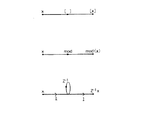
図1は本実施形態に係わるパルスモータの制御方法およびその装置における制御信号の生成手法を説明するための図、図2は図1において示した符号の意味を説明するための図である。
本実施形態に係わるパルスモータの制御方法およびその装置では、μ−ステップ方式を用いて制御信号を生成し、この制御信号を用いてパルスモータの制御を行う。また、本実施形態では、複数のμ−ステップモード相互間で制御フローをダイナミック(動的)にジャンプさせることで、ロボット動作の高速化および高精度化を図ると共に、ジャンプ補正制御を行うことで、ジャンプ時およびジャンプ後における動作の脱調を防止する。
【0012】
先ず、μ−ステップ方式について概説する。
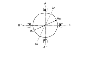
図3はコイル相電流とロータの位置との関係を示し、4相パルスモータの各相に、所定の電流比で電流が流れている状況下でのコイルに発生する磁界のベクトルをベクトルCA Cn で、又、着磁されたロータの持っている磁界ベクトルをベクトルMA Mn で表している。尚、実際には、ベクトルCA Cn ,ベクトルMA Mn は、一本ではない。但し、A,A ̄相及びB,B ̄相の電流は、各々は同じであり、各々をI(AA ̄),I(BB ̄)と表す。尚、ベクトルXYは、点Xから点Yへの向きを有し、大きさが(X2 +Y2 )1/2 のベクトルを示す。
【0013】
このとき、ベクトルMA Mn とベクトルCA Cn とが一致するロータの位置が安定点である。従って、ベクトルMA Mn を時間と共に回転させれば、ベクトルCA Cn つまりロータは、ベクトルMA Mn にと共に回転する。これがパルスモータの基本原理である。
今、電流I(AA ̄),I(BB ̄)を所定の比で流すと、ベクトルCA Cn は所定の方向を向き、ロータも当該方向に移動して停止する。このようなパルスモータのドライバーでは、電流I(AA ̄),I(BB ̄)との値に応じてロータ安定点を細かく設定できる。この様な機能を持つドライバーをμ−ステップ機能付きドライバーと呼ぶ。
【0014】
上述したμ−ステップ方式を採用したドライーでは、図3が示すように、各相に流す電流値は制御により、ベクトルMA Mn のステップ角、つまりロータのステップ角(δθ)を以下に示す例えば5種類持てるようになっている。つまり、パルスモータ(ドライバー)に1パルスを入力したときのモータ軸の回転角がステップ角(δθ)である。
【0015】
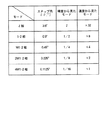
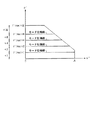
この5種類のモードは、例えば図4に示すようにまとめることができる。
図4に示す例では、μ−ステップ方式のモードは5種類あるが、ロボットはタクトすなわち速度を重視する場合が多いので、以下速度から見たモード名を用いる。これは、VTRの早送りの速度を言い表すのに似ている。
よって、×1倍速モードは最も遅く、精度は最も良く3200歯相当である。一方、×32倍速モードは最も速いが、精度が最も悪く100歯相当である。このため、本実施形態では、コントローラの位置指令は×1倍速モードを基準として、すなわちロータリーエンコーダにおいて3200(360°/0.1125°)歯を基準として全て計算される。
【0016】
次に、上述したμ−ステップモードとTN特性の関係を調べる。
この関係は、図5のように示される。
ここで、TN特性とは、モータトルク(T)と速度(N)との関係に応じて決定される特性をいい、例えば図5に示すようにθ”を横軸とし、θ’を縦軸としたTN線図を用いて表される。θ’はロータの回転角θの1階微分を示し、θ”は回転角θの2階微分を示している。
【0017】
ドライバー及びパルスモータを含めたロボットのアクチュエータにおける最高トルク、最高速度および動作許容領域などの性能はTN線図を用いて示され、ロボットの動作はかかるTN線図が示す限界ラインの範囲内において決定されなければならない。すなわち、TN線図が示す限界ラインを越えた制御を行おうとすると、脱調などが生じ、ロボットの機能そのものが損なわれてしまう。
ドライブ電流が一定の場合、μ−ステップ速度モードによってTN特性O ̄ABCDは皆同じである。ただ、その最高速度のみが各種類によって制限される。従って、ハードウェア構成によって、×1倍速モードがTN特性O ̄ABCDを全部カバーしてしまうこともあり得る。本実施形態では、θ’(MAX)ができるだけ大きくなるように、パルス発生器およびモータ電源電圧を設計し、短タクトタイム(高速性)を実現している。
【0018】
以下、本実施形態に係わるパルスモータの制御方法における制御信号の生成手法について説明する。
ところで、ステップモータを採用したロボットの動作種類には、(1)PTP動作 (2)CP動作 (3)トラッキング動作 (4)(1)〜(3)の特殊動作などが考えられるが、いずれも短タクト、高精度が要求される。
一方、TN特性は例えば図5に示すように、一般的には、×2n 倍速モード毎に最高速度、最高精度が異なる。
よって、短タクト、高精度動作をパルスモータにさせる場合、μ−ステップの×2n 倍速モードを必要に応じ、ダイナミックに選択して動作させる必要がでてくる。
本実施形態では、このように、μ−ステップの×2n 倍速モードを自由に選択ジャンプする場合、移動量に過不足を生じさせず、かつジャンプ時点で脱調せず、機械的な衝撃を与えないμ−ステップモード間ジャンプ補正制御を行う。
【0019】
μ−ステップモード間ジャンプ補正制御を説明する前に、当該制御において考慮すべき事項について概説する。
前述した(1)〜(4)のいずれの動作においても、サンプリング時間Tsの間にパルスモータに何パルス分回転して欲しいのかコントローラは算出し、これをサンプリング時間Ts毎にドライバーに送る。今、例えば×2n 倍速モード(n=0〜5)が選択されているとき、サンプリング時間Ts間にKパルス動作する指令値が連続して出力されていれば、モータは定速回転をしていることとなる。このような動作中に例えばμ−ステップモードを×2n'(n’>n)倍速モードに変更した場合、同時にKをK×2n-n'に変更しないとモータは速度が変化し、周期的なトルクリップルを発生させることとなる。例えば、Kが素数だった場合を考えれば後述するように明らかである。特に、PTP動作のように、目標移動量が決まっている場合、モード間をジャンプすると目標位置がずれるおそれがある。
【0020】
従って、μ−ステップモード×1倍速〜×32倍速間をどのようにモードジャンプしても目標位置をずれずかつトルクリップルをも発生しない制御が必要になる。
具体例的に述べると、
〔1〕定速回転動作
×1倍速モードで、サンプリング時間Ts毎にKパルスをドライバーに送ってパルスモータを定速回転させているときに、何らかの必要が生じて×4倍速モードにジャンプさせた場合におけるサンプリング時間Ts毎のパルス列(数)を考えてみると、図6のように表すことができる。
パルスモータドライバーにサンプリング時間Ts毎にKパルスを送る(書込む)と、サンプリング時間Ts毎にKパルス分だけ、ロボットの動作を駆動するロータが回転する。さて、図6において、P−Pのタイミングで×1倍速モードから×4倍速モードへのジャンプが発生すると、mod(K/4)=0,1/4,2/4,3/4の4つの場合が生じるが、0を除いて整数値ではないため、この情報はパルスモータにおいてパルス列に反映することはできない。そのため、モータの回転数が、この分だけ変化してしまう。また、図6に示すP’−P’にて×4倍速モードから×1倍速モードに戻る場合、mod(K/4)による影響も加味してKを復元しないと、さらに回転速度が変化してしまう。
【0021】
〔2〕PTP,CP,トラッキング動作
前述した〔1〕の例では定速回転であるから、パルスのKが決まればmod(K/4)も決まるため、種々の工夫をすることによってモードジャンプ時の速度変化を防ぐ方法が考えられる。しかし、ロボットでは、PTP,CP,トラッキング動作などがあり、これらの動作では、Kが時々刻々と変化するため、mod(K/4)もランダムに変化する。さらに、モードジャンプが×1倍速から×4倍速ばかりではなく、5種類のうち任意のモードから他の任意のモードへのジャンプは、120通りもあり、mod(K/2n )は、0,1/2,1/4,2/4,3/4,1/8,2/8,3/8,4/8,5/8,6/8,7/8,1/16,2/16,...,1/32,2/32,...,31/32など、計58種類ものケースが考えられる。この結果、各モード間ジャンプ個々に対応した補正アルゴリズムでなく、共通な一般的な制御が必要になる。
【0022】
次に、μ−ステップモード間ジャンプ補正制御について説明する。
μ−ステップモード間ジャンプ補正制御では、上述した〔1〕,〔2〕の事項を考慮して、μ−ステップモード間ジャンプによって発生するパルス数エラー対策を行う。
先ず、μ−ステップモード間ジャンプ補正制御を説明するにあたって使用する記号の意味について説明する。
【0023】
・N:正整数であり、現サンプリング時刻(t=iTs)の次のサンプリングタイミング(t=(i+1)Ts)までにモータが移動して欲しい×1倍速モードでのパルス数を表す。このNの値は、コントローラにて必要に応じて計算される。μ−ステップモード間ジャンプ補正制御では、Nに対して後述する操作を施す。
【0024】
・×2n',×2n"
n’,n”共に、0,1,2,3,5の各値をとる。これは速度モードを示し、この値は後述する操作の結果に応じて同時にドライバーに送られる。尚、一般性を損なうことなく、n’≦n”とする。
【0025】
・〔x〕:ガウスの記号を示し、実数xを越えない最大の整数を表す。例えば〔3.1〕=〔3.9〕=3である。尚、〔x〕はシグナル図では図2に示すように表す。
【0026】
・m:0≦m<1であり、μ−ステップモード間ジャンプ補正制御の主役となるパラメータでイニシャル時に0にリセットされる。演算途中で瞬間的にm≧1となるが、最終的には0≦m<1となる。
【0027】
・mod(X):実数xの小数点部分を表す。例えばmod(3.1)=mod(5.1)=0.1である。シグナル図では図2に示すように表す。
・Z-1:遅延子を示し、これを用いることで積分はシグナル図で図2に示すように表す。
【0028】
2n'倍速モードでのμ−ステップモード間ジャンプ補正制御は、モード間ジャンプ時の境界処理もあるが、一度、2n'倍速モードに入った後の処理も重要である。
μ−ステップモード間ジャンプ補正制御における2n'倍速モードに入った後の処理について説明する。
この場合の処理のシグナル図を図1に示す。
図1に示すように、当該処理においては、コントローラからのモード切換信号S1および指令値S3がパルスモータドライバーに出力される。また、バーチャルモータVMは、コントローラから入力した×1倍速モード信号S2に対して、整定改善と脱調対策としての所定のフィルタリング処理を行い、Nを生成する。パルスモータドライバーには、モード切換信号S1とN’を示す信号S3出力される。
【0029】
最初に、図1に示す各ノードの意味および働きを説明する。
・ノードn1 (実数値):図1に示すように、n1 =N/2n'であり、この値は実数値である。
【0030】
・ノードn2 :0≦n2 <1の実数値であり、図1に示すように、n2 =mod(n1 )=mod(N/2n')となる。ここで、n2 は割り算の結果の小数点部分となっている。例えば、mod(13/2)=mod(6.5)=0.5である。
【0031】
・ノードn3 :n3 =0又は1である。図1に示すように、n3 =〔m〕=0又は1である。n3 =0又は1は以下に説明するmの性質による。
・m:0≦m<1である。但し、mは瞬間的に1を越えることがある。図1を用いて説明すると、先ず、n2 を積分した結果に対して〔 〕をとる。その結果、下記式(1)のようになる。
【0032】
【数1】
n3 =0(0≦m<1の場合) (1)
n3 =1(m≧1の場合)
【0033】
そして、n3 の値をmから引くつまり、0又は1を引く。これによって、最終的にmは0≦m<1となる。尚、n3 はN’に加算される。
・N’:N’は×2n'倍速モードにおけるパルスモータへの指令値である。図1より、下記式3−6に基づいて処理される。
【0034】
【数2】

n1 =N/2n'は実数で、この値そのものをパルスモータに送ることができれば簡単であるが、パルスモータはパルス数、つまり整数値でしか動作でいないので、整数化する。ここで、必ずn1 以下の整数値をとる〔n1 〕にn3 を加算してN’とし、ドライバーに送る。そして、この一連の操作で捨ててしまった小数点部分n1 −〔n1 〕を貯めておいて(積分して)、この積分値mが「1」をオーバーした時点で、つまり後からこの「1」を〔n1 〕に加えることで捨ててしまった小数点部分を取り戻す。この1は定速動作では周期的に、その他の動作では非周期的に生じる。
【0036】
以上説明した、2n'倍速モードを例に用いて、μ−ステップモード間ジャンプ補正制御を時間軸から見て説明する。
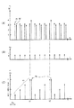
実際の応用では、Nはサンプリング時間Ts毎にダイナミックに変化し、同様に、n’もその値を変えていく。そのあらゆる場合について説明することはできないので、ここでは、N=13(一定),n’=2(一定)のケースについて図7に示すタイムチャートを用いて説明する。
【0037】
図7に示すように、タイミングt1 ,t2 ,..の時、積分値mは丁度「1」に達するため、〔m〕=n3 =1となり、この「1」をN’に加え、mから差し引いていることを表している。つまり、エラー分n2 は積分されmとなり、mが「1」をオーバーする度にN’に補正がかかる仕組みである。このケースの場合、エラー補正周期は4Ts(≒40msec=25HZ)であり、この周期をリミッターサイクルとも言う。
【0038】
これまでは、モード間ジャンプ後の補正について説明したが、ここでは、μ−ステップモード間ジャンプの直後の補正制御を説明する。
モード間ジャンプは、常に、2つのモード×2n'倍速モードと×2n"倍速モードとの間でのみ行われ、0≦n’<5,0≦n”<5である。また、説明を一般化するために、n’=n”つまりジャンプ無しの場合を含むと考える。また、n’≦n”と決めても一般性は損なわれない。まとめると下記式(3)に示す条件でのジャンプ直後の補正について述べる。
【0039】
【数3】
0≦n’≦5
0≦n”≦5
n’≦n” (3)
【0040】
μ−ステップモード間ジャンプの直後の補正制御について、×2n'倍速モードから×2n"倍速モードへのジャンプを例として用いて説明する。
これは、高速モードへとジャンプする場合であり、この場合の補正制御処理のシグナル図は図8のようになる。
【0041】
図8に示すように、当該処理においては、コントローラからのモード切換信号S11および指令値S13がパルスモータドライバーに出力される。また、バーチャルモータVMは、コントローラから入力した×1倍速モード信号S12に対して、整定改善と脱調対策としての所定のフィルタリング処理を行い、Nを生成する。パルスモータドライバーには、モード切換信号S1とN’を示す信号S13出力される。スイッチSW1の切り換えは、モード切換信号S11に基づいて行われる。
【0042】
図8において、所定のサンプリングタイミングにてスイッチSW1を1/2n"側に倒す直前にノードmに対して下記式(4)で示される操作を施す。
【0043】
【数4】
m=m/2n"-n' (4)
【0044】
このとき、下記式(5)が成り立つ。
【数5】
n3 =〔m〕=0(∵n”≧n’) (5)
【0045】
そのため、N’は何の影響も受けない。
次に、スイッチSW1を1/2n 側に倒し、後は、前述したモードジャンプ補正アルゴリズムを実行する。尚、スイッチSW1を倒した後からn1 は下記式(6)に示すように変化する。
【0046】
【数6】
n1 =n1 /2n"-n' (6)
【0047】
すなわち、スイッチSW1が倒れる前後で2n"-n' 倍の段差が発生するが、同時にパルスモータドライバーのドライブモードも×2n"倍速モードに変更をかけるのでパルスモータ軸の速度は変わらない。
【0048】
次に、μ−ステップモード間ジャンプの直後の補正制御について、×2n"倍速モードから×2n'倍速モードへのジャンプを例として用いて説明する。
図8にて、所定のサンプリングタイミングにてスイッチSW1を1/2n'側に倒す直前にノードmに対して下記式(7)で示される操作を施す。
【0049】
【数7】
m=m/2n'-n" (7)
【0050】
整数値n3 =〔m〕は、n’−n”の大小によってとり得る値は変わるが、n”−n’=5の時、最大値は31にもなる。
しかし、実用上、下記式(8)が成り立つ、
【0051】
【数8】
n”=n+1 (8)
【0052】
つまり隣りのμステップモード間のジャンプを考えるのが普通であるから、下記式(9)が成り立つ。
【0053】
【数9】
n3 =〔m〕=0又は1 (9)
【0054】
そのため、この値をN’に加算し、mからこの値を差し引き、後は、図1を用いて前述したμ−ステップモード間ジャンプ補正制御を実行する。よって、スイッチSW1が、×2n"倍速モードから×2n'モード倍速に切り換えられるタイミングではN’は、上記式(2)による「+1」と、上記式(9)による「+1」の計「+2」が発生する可能性がある。
しかし、このとき、パルスモータのモードも×2n'に変更されているので、パルスモータ軸の角度は×2n"倍速モードの1パルスと同じであるから、実用に殆ど問題ないと思われる。
尚、式(8)の条件は必ずしも必要ではなく、例えば〔m〕=31をそのままN’に加算しても良い。これは、パルスモータのモードも×2n'倍速モードに変更されるためである。
【0055】
次に、μ−ステップモード間ジャンプ補正制御におけるμ−ステップモードの切換タイミングについて説明する。
図5でも説明したように、パルスモータドライバーのモータ電圧VCCM が充分に高くかつパルス発生ハードウェアが充分に高い周波数のパルス列fpを発生可能であれば、TN特性の速度軸(θ’)はμ−ステップモード毎に帯状に領域分けされる。VCCM が小さかったりパルス列fpを充分大きくできないと、図5に示す各領域が重なってくる。このことは、ベアリング寿命も関係してくる。いずれにしても、ある倍速モードが出し得る最大速度は、パルスモータ+ドライバーシステムで一意的に決定される。この状況を図9に示す。尚、図9に示す特性は、パルスモータの電圧および電流を一定にした場合のものである。
【0056】
図9に示す実測データが得られたら各倍速モードでの最高速度をコントローラはデータベースとして持ち指令速度θr’が与えられたとき、θr’を実現できる最も低速モードで動作するように、具体的には、θr’より大きいθ’(max)×2n のうち最小の最高速度の倍速モードを選択するように、ダイナミックにモードを切り換えていけば精度上最も好ましい。こうすることで、短タクト高精度動作がロボットのどんな動作(PTP,CP,トラッキング)でも可能となる。
また、本実施形態に係わるパルスモータの制御方法およびその装置によれば、パルスモータのTN特性をフルに利用した制御が可能になり、その性能をさらに高めることができる。
【0057】
第2実施形態
本実施形態に係わるμ−ステップモード間ジャンプ補正制御は、上述した第1実施形態に係わるパルスモータの制御方法において、機械的な共振発生を防止するものである。基本的な構成は、上述した第1実施形態と同じである。
図10は、本実施形態に係わるパルスモータの制御方法およびその装置における制御信号の生成処理を説明するための図である。
図10に示すように、当該処理においては、コントローラからのモード切換信号S21および指令値S23がパルスモータドライバーに出力される。また、バーチャルモータVMは、コントローラから入力した×1倍速モード信号S22に対して、整定改善と脱調対策としての所定のフィルタリング処理を行い、Nを生成する。パルスモータドライバーには、モード切換信号S21とN’を示す信号S23出力される。スイッチSW2の切り換えは、モード切換信号S21に基づいてサンプリング時間Ts毎に行われる。
【0058】
先ず、本実施形態に係わるパルスモータの制御方法を説明する前に、考慮すべき事項について説明する。
パルスモータロボットの問題点の一つに、走行時における機械的共振の問題がある。このような機械的共振が発生すると、走行精度の確保が難しくなり、振動音が発生し、動作上好ましくない。
かかる機械的共振の発生原理は、単純で、パルスモータのステップ周期(周波数)と、パルスモータロボットの機械系の共振周波数が近づき(時には一致し)、機械を揺するというものである。
【0059】
かかる問題点を解決するために、従来では、主に次の対策を講じてきた。
(1)速度や負荷について使用仕様内に共振点を持たないように機械設計を行う。
(2)共振が発生したら、ユーザにμ−ステップモードを変更してもらう。
(3)共振が発生したら、ユーザに速度を変更してもらう。
(4)共振が発生したら、ユーザに負荷を変更してもらう。
以上のうち、(1)ではロボットの速度が100〜1%間を1%刻みで変更でき、しかも負荷も2〜10kg程変わり得るため、極めて困難である。
また、(2)は、共振の発生を抑制することが可能であるが、ユーザの負担が大きいと共に、μ−ステップモードの変更で精度が悪化するおそれがある。
さらに、(3),(4)は、原理上、最も優れているが、ユーザの負荷が大きいと共に、速度又は負荷の変更ができない場合の方が多いという問題がある。
尚、この機械的共振の問題は、パルスモータロボット固有の問題ではなく、パルスモータを採用する各種機器(FA,OA)などに共通の問題である。
【0060】
次に、機械的共振の発生メカニズムについて説明する。
パルスモータを定速回転させる場合、図11に示すように、サンプリング時間Ts間に一定数のパルス数Nを与え続ける。
図11の場合、Ts間に3個のパルスが発生することから、1秒間に3/Ts発、つまり周波数3/Ts〔Hz〕の成分でモータ軸がステップ的に回転するから、モータ軸にもし3/Ts〔Hz〕及びその高調波を持つ機械的共振系が存在したら、かかる機械的共振系が強制持続振動してしまう。これが機械的共振発生メカニズムである。周波数特性的に言えば、図12に示すf特(周波数特性)を持つ機械系がパルスモータのモータ軸に直結されている場合、上記パルス周波数N/Ts〔Hz〕=fpが下記式(10)のようになったときに、機械的共振が発生する。ここで、frは共振周波数を示している。
【0061】
【数10】
fp≒fr (10)
【0062】
fp=N/Tsは、Nの値と共に、つまりロボット速度で変化するため、ある速度で式(10)の関係が成り立ってしまう。さらに、fr自身はロボットのワーク等の重量で、こちらも変化するため、やはり、式(10)の関係が成立してしまう。
このように上記式(10)の関係がある速度、ある負荷で成立してしまうのは宿命的とも言え、機械設計だけで、この問題を解決するのは困難である。
【0063】
本実施形態に係わるパルスモータの制御方法は、上述したような問題を考慮しており、機械的共振の発生を効果的に抑制するものである。
以下、本実施形態に係わるパルスモータの制御方法における機械的共振対策手法について説明する。
本実施形態では、以下の(1)〜(3)の事項を考慮して機械的共振を抑制している。
(1)パルスモータ動作精度はできるだけ高くする。つまり、×20 ,×21 ,..,×2n ,..モード中nはできるだけ小さくする。すなわち、ステップ角を小さくする。
(2)ユーザへの負担をできるだけ小さくする。
(3)ロボット機構、ロボット速度・負荷毎に異なった対策をとらない。
【0064】
図10を用いて、本実施形態に係わるパルスモータの制御方法を説明する。
本実施形態では、μ−ステップモードにおける×20 倍速モードと×21 倍速モードとをアトランダムに切り換える。このとき、μ−ステップモード間ジャンプ補正制御を併用する。
図10において、
・random( ):サンプリング時間Ts毎にランダムな値を計算する関数であり、その計算結果に応じて生成されたランダムモード切換信号によってパルスモータのモードおよびスイッチSWの切り換えが制御される。
・同時に、図8を用いて前述したμ−ステップ補正アルゴリズムを働かせる。
【0065】
本実施形態に係わるパルスモータの制御方法における機械的共振防止原理について説明する。
図10のように、μ−ステップモードをアトランダムに切り換えると、パルス周波数(×20 倍速モード時fp20 、×21 倍速モード時fp21 )は、図13に示すようにアトランダムに揺すられる。その結果、もし、いずれかが共振周波数frと一致しても機械的共振が成長する前に共振周波数frからずれることとなり、機械的共振が成長できない。
従って、本実施形態によれば、共振周波数frが何処にあっても構わないこととなる。つまり、機械設計時共振対策に多くの時間とコストをかける必要がなくなる。
【0066】
尚、図10では、×20 倍速モードと×21 倍速モードとの間でスイッチSWによる切り換えを行う場合であるがモードをもっと増やして×20 ,×21 ,×22 間のアトランダムスイッチSWを用いても精度が許せば構わない。さらに、M系列発生回路をドライバー側に内蔵してモードを切り換える方式も考えられる。
仮に、図10をアンチ機械共振ドライブと呼んだ場合、通常動作では、このアンチ機械共振ドライブは使わず、機械共振が気になってきた段階で、このアンチ機械共振ドライブができるように、速度ピーク到達時間Tp若しくはロボット言語で対応できるようにしておくのが好ましい。
【0067】
【発明の効果】
以上説明したように、本発明のパルスモータの制御方法およびその装置によれば、短タクトタイムで高精度な動作をモータに行わせることができる。
また、本発明のパルスモータの制御方法およびその装置によれば、パルスモータのTN特性をフルに利用した制御が可能になり、その性能をさらに高めることができる。
さらに、本発明のパルスモータの制御方法およびその装置によれば、ロボットなどのモータによる駆動対象の機械共振を抑制することができる。
【図面の簡単な説明】
【図1】本発明の第1実施形態に係わるパルスモータの制御方法を説明するための図である。
【図2】図1において示した符号の意味を説明するための図である。
【図3】パルスモータの原理を説明するための図である。
【図4】μ−ステップモードの種類を説明するための図である。
【図5】μ−ステップモードとTN特性の関係を示す図である。
【図6】μ−ステップモード間ジャンプ補正制御において考慮すべき事項を説明するための図である。
【図7】μ−ステップモード間ジャンプ補正制御を時間軸から見て説明するための図である。
【図8】μ−ステップモード間ジャンプの直後の補正制御を説明するための図である。
【図9】μ−ステップモードの切換タイミングを説明するための図である。
【図10】本発明の第2実施形態に係わるパルスモータの制御方法を説明するための図である。
【図11】パルスモータを定速回転させた場合に、サンプリング時間Ts間に発生するパルスを説明するための図である。
【図12】機械共振が発生する周波数を説明するための図である。
【図13】図10に示すパルスモータの制御方法における周波数を説明するための図である。
【符号の説明】
S1,S11,S12… モード切換信号
S2,S12,S22… ×1倍速モード信号
VM… バーチャルモータ[0001]
BACKGROUND OF THE INVENTION
The present invention relates to a method and apparatus for controlling a pulse motor.
[0002]
[Prior art]
In recent years, horizontal articulated robots (hereinafter simply referred to as robots) employing pulse motors have been developed. In such a robot, it is important to reduce the tact time and increase the accuracy. As such a technique, for example, a robot employing a μ-step mode is known. The μ-step mode has a plurality of double speed modes. However, in the conventional horizontal joint robot, a single double speed mode is selected and the pulse motor is controlled by continuously using this double speed mode. . Note that the multiple speed modes have mutually different speed and accuracy characteristics in the control of the pulse motor.
[0003]
[Problems to be solved by the invention]
However, in the conventional robot described above, since the pulse motor is controlled using only a single double speed mode, the capability of the pulse motor cannot be fully exhibited, and high speed (short tact time) is achieved. There is a problem that both high accuracy and high accuracy cannot be satisfied at the same time.
Also, with conventional robots, when the stepping frequency (frequency) of the pulse motor approaches the resonance frequency of the robot's mechanical system, the mechanical system resonates, making it difficult to ensure running accuracy and generating vibration noise. The above inconvenience may occur. In order to solve such a problem, there is a method in which the user changes the speed when resonance occurs, but there is a problem that the burden on the user is heavy.
[0004]
The present invention has been made in view of the above-described prior art, and an object of the present invention is to provide a method and apparatus for controlling a pulse motor having high speed and high accuracy characteristics.
Another object of the present invention is to provide a pulse motor control method and apparatus that can suppress the occurrence of mechanical resonance without imposing a burden on the user.
[0005]
[Means for Solving the Problems]
In order to solve the above-mentioned problems of the prior art and achieve the above-mentioned object, the present inventionThe pulse motor control method ofControl of a pulse motor that rotates based on multiple rotation modes with different rotation angles per unit pulseTheWhile dynamically switching between the plurality of rotation modesA method for controlling a pulse motor, wherein the number of pulses per unit time before switching the rotation mode is divided according to a ratio of the rotation angle before and after the switching, and the integer part of the division result is used to perform the division. Determine the number of pulses per unit time after switching, accumulate the decimal part of the division result after switching the rotation mode, and add to the number of pulses per unit time when the cumulative result reaches 1 .
[0006]
Also, the control of the pulse motor of the present inventionThe apparatus is a pulse motor control device that performs control of a pulse motor that rotates based on a plurality of rotation modes having different rotation angles per unit pulse while dynamically switching the plurality of rotation modes, Divide the number of pulses per unit time before switching the rotation mode according to the ratio of the rotation angle before and after the switching, and determine the number of pulses per unit time after the switching using the integer part of the division result And a pulse number determining means for accumulating the decimal part of the division result after switching the rotation mode and adding to the pulse number of the unit time when the cumulative result reaches 1.
[0011]
DETAILED DESCRIPTION OF THE INVENTION
A pulse motor control method and apparatus according to an embodiment of the present invention will be described below.
First embodiment
FIG. 1 is a diagram for explaining a control method of a pulse motor and a method for generating a control signal in the apparatus according to the present embodiment, and FIG. 2 is a diagram for explaining the meanings of symbols shown in FIG.
In the pulse motor control method and apparatus according to this embodiment, a control signal is generated using the μ-step method, and the pulse motor is controlled using this control signal. In the present embodiment, the control flow is dynamically jumped between a plurality of μ-step modes to increase the speed and accuracy of the robot operation and perform jump correction control. Prevents step-out of movement during and after jumping.
[0012]
First, the μ-step method will be outlined.
FIG. 3 shows the relationship between the coil phase current and the position of the rotor. Vector C represents the vector of the magnetic field generated in the coil under the condition that current flows at a predetermined current ratio in each phase of the four-phase pulse motor.ACnIn addition, the magnetic field vector of the magnetized rotor is expressed as a vector M.AMnIt is represented by Actually, the vector CACn, Vector MAMnIs not one. However, the currents of the phases A and A and the phases B and B are the same, and are expressed as I (AA ̄) and I (BB ̄), respectively. The vector XY has a direction from the point X to the point Y and has a size of (X2+ Y2)1/2Indicates the vector.
[0013]
At this time, the vector MAMnAnd vector CACnIs the stable point. Therefore, the vector MAMnRotate with time, the vector CACnThat is, the rotor is vector MAMnRotate with This is the basic principle of a pulse motor.
Now, letting the currents I (AAI) and I (BB 流 す) flow at a predetermined ratio, the vector CACnTurns in a predetermined direction and the rotor also moves in that direction and stops. In such a pulse motor driver, the rotor stable point can be set finely according to the values of the currents I (AA ̄) and I (BB ̄). A driver having such a function is called a driver with a μ-step function.
[0014]
In the dryer adopting the above-described μ-step method, as shown in FIG. 3, the current value passed through each phase is controlled by the vector MAMnThe step angle of the rotor, that is, the step angle (δθ) of the rotor can be provided, for example, as shown below. That is, the rotation angle of the motor shaft when one pulse is input to the pulse motor (driver) is the step angle (δθ).
[0015]
These five modes can be summarized as shown in FIG.
In the example shown in FIG. 4, there are five types of μ-step mode. However, since robots often place importance on tact, that is, speed, the following mode names are used from the viewpoint of speed. This is similar to expressing the fast-forward speed of the VTR.
Therefore, the × 1 speed mode is the slowest and the best accuracy is equivalent to 3200 teeth. On the other hand, the × 32 speed mode is the fastest, but the accuracy is the worst and is equivalent to 100 teeth. For this reason, in this embodiment, the controller's position command is all calculated on the basis of the × 1 speed mode, that is, on the basis of 3200 (360 ° / 0.1125 °) teeth in the rotary encoder.
[0016]
Next, the relationship between the above-described μ-step mode and TN characteristics is examined.
This relationship is shown in FIG.
Here, the TN characteristic means a characteristic determined according to the relationship between the motor torque (T) and the speed (N). For example, as shown in FIG. 5, θ ″ is the horizontal axis and θ ′ is the vertical axis. ′ Is the first derivative of the rotor rotation angle θ, and θ ″ is the second derivative of the rotation angle θ.
[0017]
Performances such as maximum torque, maximum speed, and allowable operation range of robot actuators including drivers and pulse motors are shown using TN diagrams, and robot operations are determined within the limits of the limit lines indicated by such TN diagrams. It must be. That is, if the control beyond the limit line indicated by the TN diagram is performed, a step-out occurs and the function of the robot itself is impaired.
When the drive current is constant, the TN characteristics O ̄ABCD are all the same depending on the μ-step speed mode. However, only the maximum speed is limited by each type. Therefore, depending on the hardware configuration, the × 1 double speed mode may cover the entire TN characteristic O ̄ABCD. In the present embodiment, the pulse generator and the motor power supply voltage are designed so that θ ′ (MAX) is as large as possible, thereby realizing a short tact time (high speed).
[0018]
Hereinafter, a method for generating a control signal in the method for controlling the pulse motor according to the present embodiment will be described.
By the way, there are (1) PTP operation (2) CP operation (3) Tracking operation (4) Special operations (1) to (3), etc. Short tact and high accuracy are required.
On the other hand, the TN characteristic is generally x2 as shown in FIG.nMaximum speed and maximum accuracy differ for each double speed mode.
Therefore, when letting a pulse motor perform short tact and high-precision operation, μ-step × 2nIt is necessary to dynamically select and operate the double speed mode as necessary.
In the present embodiment, in this way, μ−step × 2nWhen the double speed mode is freely selected and jumped, jump correction control between μ-step modes that does not cause excess or deficiency in the movement amount, does not step out at the time of jump, and does not give mechanical shock is performed.
[0019]
Before describing the μ-step mode jump correction control, items to be considered in the control will be outlined.
In any of the operations (1) to (4) described above, the controller calculates how many pulses the pulse motor wants to rotate during the sampling time Ts, and sends this to the driver every sampling time Ts. Now, for example x2nWhen the double speed mode (n = 0 to 5) is selected, if the command value for K pulse operation is continuously output during the sampling time Ts, the motor is rotating at a constant speed. During such operation, for example, μ-step mode is set to × 2.n '(N '> n) When changing to the double speed mode, K is simultaneously set to K × 2n-n 'Otherwise, the speed of the motor will change and periodic torque ripple will be generated. For example, considering the case where K is a prime number, it is clear as will be described later. In particular, when the target movement amount is determined as in the PTP operation, the target position may be shifted when jumping between modes.
[0020]
Therefore, it is necessary to perform control that does not deviate the target position and generate torque ripple no matter how the mode jumps between the μ-step mode × 1 × speed to × 32 × speed.
As a specific example,
[1] Constant speed rotation
In × 1 double speed mode, when a pulse motor is rotated at a constant speed by sending a K pulse to the driver at every sampling time Ts, some need arises, and jumping to the × 4 double speed mode is performed every sampling time Ts. Considering the pulse train (number), it can be expressed as shown in FIG.
When a K pulse is sent (written) to the pulse motor driver every sampling time Ts, the rotor that drives the operation of the robot is rotated by the K pulses every sampling time Ts. In FIG. 6, when a jump from the x1 speed mode to the x4 speed mode occurs at the timing of PP, 4 (mod (K / 4) = 0, 1/4, 2/4, 3/4). One case occurs, but since this is not an integer value except for 0, this information cannot be reflected in the pulse train in the pulse motor. Therefore, the number of rotations of the motor changes by this amount. In addition, when returning from the x4 speed mode to the x1 speed mode at P′-P ′ shown in FIG. End up.
[0021]
[2] PTP, CP, tracking operation
In the example of [1] described above, since the rotation speed is constant, mod (K / 4) is also determined if the K of the pulse is determined. Therefore, various methods can be used to prevent a speed change at the time of mode jump. . However, the robot has PTP, CP, tracking operation, and the like. In these operations, K changes from moment to moment, so mod (K / 4) also changes randomly. Furthermore, the mode jump is not limited to x1 × to x4 × speed, but there are 120 types of jumps from any mode to any other mode among the five types, mod (K / 2n) Is 0, 1/2, 1/4, 2/4, 3/4, 1/8, 2/8, 3/8, 4/8, 5/8, 6/8, 7/8, 1 / 16, 2/16,. . . , 1/32, 2/32,. . . , 31/32, etc., a total of 58 cases can be considered. As a result, common general control is required instead of a correction algorithm corresponding to each jump between modes.
[0022]
Next, the μ-step mode jump correction control will be described.
In the μ-step mode jump correction control, the above-mentioned items [1] and [2] are taken into consideration, and a countermeasure for the number of pulses error caused by the μ-step mode jump is taken.
First, the meanings of symbols used in explaining jump correction control between μ-step modes will be described.
[0023]
N is a positive integer and represents the number of pulses in the 1 × speed mode that the motor wants to move by the next sampling timing (t = (i + 1) Ts) after the current sampling time (t = iTs). The value of N is calculated as necessary by the controller. In the μ-step mode jump correction control, an operation described later is performed on N.
[0024]
・ × 2n ', X2n "
Both n ′ and n ″ take values of 0, 1, 2, 3, and 5. This indicates a speed mode, and this value is sent to the driver at the same time according to the result of an operation described later. N ′ ≦ n ″ without impairing.
[0025]
[X]: Indicates a Gaussian symbol and represents the largest integer not exceeding the real number x. For example, [3.1] = [3.9] = 3. [X] is represented in the signal diagram as shown in FIG.
[0026]
M: 0 ≦ m <1, and is a main parameter of jump correction control between μ and step mode, and is reset to 0 at the initial time. In the middle of the calculation, m ≧ 1 instantaneously, but finally 0 ≦ m <1.
[0027]
Mod (X): represents the decimal point part of the real number x. For example, mod (3.1) = mod (5.1) = 0.1. In the signal diagram, it is represented as shown in FIG.
・ Z-1: Indicates a retarder, and by using this, the integral is represented by a signal diagram as shown in FIG.
[0028]
2n 'The jump correction control between μ and step mode in the double speed mode has boundary processing at the time of jump between modes.n 'Processing after entering the double speed mode is also important.
2 in μ-step mode jump correction controln 'Processing after entering the double speed mode will be described.
A signal diagram of the treatment in this case is shown in FIG.
As shown in FIG. 1, in this process, the mode switching signal S1 and the command value S3 from the controller are output to the pulse motor driver. Further, the virtual motor VM performs a predetermined filtering process as a settling improvement and a step-out countermeasure with respect to the × 1 double speed mode signal S2 input from the controller, and generates N. A signal S3 indicating mode switching signals S1 and N 'is output to the pulse motor driver.
[0029]
First, the meaning and function of each node shown in FIG. 1 will be described.
・ Node n1(Real value): n as shown in FIG.1= N / 2n 'This value is a real value.
[0030]
・ Node n2: 0 ≦ n2<1 is a real value, and as shown in FIG.2= Mod (n1) = Mod (N / 2n ') Where n2Is the decimal part of the result of division. For example, mod (13/2) = mod (6.5) = 0.5.
[0031]
・ Node nThree: NThree= 0 or 1. As shown in FIG.Three= [M] = 0 or 1. nThree= 0 or 1 depends on the property of m described below.
M: 0 ≦ m <1. However, m may exceed 1 instantaneously. Referring to FIG. 1, first, n2[] Is taken for the result of integrating. As a result, the following formula (1) is obtained.
[0032]
[Expression 1]
nThree= 0 (when 0 ≦ m <1) (1)
nThree= 1 (when m ≧ 1)
[0033]
And nThreeIs subtracted from m, that is, 0 or 1 is subtracted. As a result, m finally becomes 0 ≦ m <1. NThreeIs added to N '.
N ': N' is x2n 'This is a command value to the pulse motor in the double speed mode. From FIG. 1, processing is performed based on the following expression 3-6.
[0034]
[Expression 2]
n1= N / 2n 'Is a real number, and it is easy if this value itself can be sent to the pulse motor. However, since the pulse motor operates only with the number of pulses, that is, an integer value, it is converted into an integer. Where n1Takes the following integer value [n1] To nThreeIs added to N 'and sent to the driver. And the decimal point part n thrown away by this series of operations1-[N1] Is accumulated (integrated), and when the integrated value m exceeds “1”, that is, after this “1” is set to [n1] To get back the discarded decimal point. This 1 occurs periodically in constant speed operation and non-periodically in other operations.
[0036]
2 explained aboven 'Using the double speed mode as an example, the jump correction control between μ and step modes will be described with reference to the time axis.
In an actual application, N changes dynamically every sampling time Ts, and similarly n 'changes its value. Since all cases cannot be described, here, the case of N = 13 (constant) and n ′ = 2 (constant) will be described with reference to the time chart shown in FIG.
[0037]
As shown in FIG.1, T2,. . Since the integral value m just reaches “1”, [m] = nThree= 1, indicating that “1” is added to N ′ and subtracted from m. In other words, error n2Is integrated into m, and every time m exceeds “1”, N ′ is corrected. In this case, the error correction cycle is 4Ts (≈40 msec = 25 HZ), and this cycle is also called a limiter cycle.
[0038]
So far, the correction after the jump between modes has been described, but here, the correction control immediately after the jump between μ-step modes will be described.
Jump between modes is always 2 modes x 2n 'Double speed mode and x2n "This is performed only in the double speed mode, and 0 ≦ n ′ <5, 0 ≦ n ″ <5. In order to generalize the explanation, it is considered that n ′ = n ″, that is, the case of no jump is included. . Further, even if n ′ ≦ n ″ is determined, generality is not impaired. In summary, correction immediately after a jump under the condition shown in the following formula (3) will be described.
[0039]
[Equation 3]
0 ≦ n ′ ≦ 5
0 ≦ n ”≦ 5
n ′ ≦ n ”(3)
[0040]
x2 for correction control immediately after jump between μ-step moden '× 2 from double speed moden "A description will be given using a jump to the double speed mode as an example.
This is a case of jumping to the high speed mode, and the signal diagram of the correction control process in this case is as shown in FIG.
[0041]
As shown in FIG. 8, in this process, the mode switching signal S11 and the command value S13 from the controller are output to the pulse motor driver. Further, the virtual motor VM performs a predetermined filtering process as a settling improvement and a step-out countermeasure on the × 1 double speed mode signal S12 input from the controller, and generates N. A signal S13 indicating mode switching signals S1 and N 'is output to the pulse motor driver. The switch SW1 is switched based on the mode switching signal S11.
[0042]
In FIG. 8, the switch SW1 is halved at a predetermined sampling timing.n "The operation shown by the following formula (4) is performed on the node m immediately before it is tilted to the side.
[0043]
[Expression 4]
m = m / 2n "-n ' (4)
[0044]
At this time, the following equation (5) holds.
[Equation 5]
nThree= [M] = 0 (∵n ″ ≧ n ′) (5)
[0045]
Therefore, N 'is not affected at all.
Next, switch SW1 is set to 1/2.nAfter that, the mode jump correction algorithm described above is executed. In addition, after depressing switch SW1, n1Changes as shown in the following equation (6).
[0046]
[Formula 6]
n1= N1/ 2n "-n ' (6)
[0047]
That is, 2 before and after the switch SW1 falls.n "-n 'Double step occurs, but the drive mode of the pulse motor driver is also x2n "Because the speed mode is changed, the speed of the pulse motor shaft does not change.
[0048]
Next, with respect to correction control immediately after the jump between μ-step modes, × 2n "× 2 from double speed moden 'A description will be given using a jump to the double speed mode as an example.
In FIG. 8, the switch SW1 is halved at a predetermined sampling timing.n 'The operation shown by the following formula (7) is performed on the node m immediately before it is tilted to the side.
[0049]
[Expression 7]
m = m / 2n'-n " (7)
[0050]
Integer value nThree= [M] varies depending on the magnitude of n′−n ″, but the maximum value is 31 when n ″ −n ′ = 5.
However, in practice, the following equation (8) holds:
[0051]
[Equation 8]
n ″ = n + 1 (8)
[0052]
That is, since it is normal to consider a jump between adjacent μ step modes, the following equation (9) holds.
[0053]
[Equation 9]
nThree= [M] = 0 or 1 (9)
[0054]
Therefore, this value is added to N ′, and this value is subtracted from m. Thereafter, the jump correction control between the μ and step modes described above with reference to FIG. 1 is executed. Therefore, switch SW1 is × 2.n "× 2 from double speed moden 'At the timing of switching to the mode double speed, there is a possibility that N ′ may generate a total “+2” of “+1” according to the above equation (2) and “+1” according to the above equation (9).
At this time, however, the pulse motor mode is also x2.n 'The angle of the pulse motor shaft is x2n "Since it is the same as one pulse in the double speed mode, there seems to be almost no problem in practical use.
Note that the condition of the equation (8) is not necessarily required, and for example, [m] = 31 may be added to N ′ as it is. This is also a pulse motor mode × 2n 'This is because the mode is changed to the double speed mode.
[0055]
Next, the switching timing of the μ-step mode in the μ-step mode jump correction control will be described.
As explained in FIG. 5, the motor voltage V of the pulse motor driverCCMIs sufficiently high and the pulse generation hardware can generate a pulse train fp having a sufficiently high frequency, the speed axis (θ ′) of the TN characteristic is divided into strips for each μ-step mode. VCCMAre small or the pulse train fp cannot be made sufficiently large, the areas shown in FIG. 5 overlap. This is also related to bearing life. In any case, the maximum speed that can be obtained in a certain double speed mode is uniquely determined by the pulse motor + driver system. This situation is shown in FIG. The characteristics shown in FIG. 9 are obtained when the voltage and current of the pulse motor are constant.
[0056]
When the actual measurement data shown in FIG. 9 is obtained, the controller has the maximum speed in each double speed mode as a database, and when command speed θr ′ is given, it is specifically set so that it operates in the slowest mode that can realize θr ′. Is larger than θr ′, θ ′ (max) × 2nOf these, it is most preferable in terms of accuracy if the mode is dynamically switched so as to select the minimum speed double speed mode. By doing so, a short tact high-precision operation is possible for any operation (PTP, CP, tracking) of the robot.
In addition, according to the method and apparatus for controlling a pulse motor according to the present embodiment, it is possible to make full use of the TN characteristics of the pulse motor and further improve its performance.
[0057]
Second embodiment
The μ-step mode jump correction control according to the present embodiment prevents mechanical resonance from occurring in the pulse motor control method according to the first embodiment described above. The basic configuration is the same as that of the first embodiment described above.
FIG. 10 is a view for explaining a control method of the pulse motor according to the present embodiment and a control signal generation process in the apparatus.
As shown in FIG. 10, in this process, the mode switching signal S21 and the command value S23 from the controller are output to the pulse motor driver. Further, the virtual motor VM performs a predetermined filtering process as a settling improvement and a step-out countermeasure on the × 1 double speed mode signal S22 input from the controller, and generates N. A signal S23 indicating mode switching signals S21 and N 'is output to the pulse motor driver. The switch SW2 is switched every sampling time Ts based on the mode switching signal S21.
[0058]
First, before describing the method of controlling the pulse motor according to the present embodiment, items to be considered will be described.
One problem with pulse motor robots is the problem of mechanical resonance during travel. When such mechanical resonance occurs, it becomes difficult to ensure traveling accuracy, and vibration noise is generated, which is not preferable in operation.
The principle of occurrence of such mechanical resonance is simple: the step period (frequency) of the pulse motor approaches the resonance frequency of the mechanical system of the pulse motor robot (sometimes coincident), and the machine is shaken.
[0059]
In order to solve such problems, conventionally, the following measures have been mainly taken.
(1) Design the machine so that there is no resonance point within the operating specifications for speed and load.
(2) When resonance occurs, ask the user to change the μ-step mode.
(3) When resonance occurs, ask the user to change the speed.
(4) When resonance occurs, ask the user to change the load.
Of the above, in (1), the speed of the robot can be changed in increments of 1% between 100% and 1%, and the load can change by about 2-10 kg, which is extremely difficult.
In (2), it is possible to suppress the occurrence of resonance, but the burden on the user is large and the accuracy may be deteriorated by changing the μ-step mode.
Furthermore, although (3) and (4) are the best in principle, there are problems that the load on the user is large and there are many cases where the speed or load cannot be changed.
This problem of mechanical resonance is not a problem specific to the pulse motor robot, but a problem common to various devices (FA, OA) and the like that employ the pulse motor.
[0060]
Next, the generation mechanism of mechanical resonance will be described.
When the pulse motor is rotated at a constant speed, as shown in FIG. 11, a constant number of pulses N is continuously given during the sampling time Ts.
In the case of FIG. 11, since three pulses are generated during Ts, the motor shaft rotates stepwise with a component of 3 / Ts per second, that is, a frequency of 3 / Ts [Hz]. If there is a mechanical resonance system having 3 / Ts [Hz] and its harmonics, the mechanical resonance system is forced to vibrate. This is the mechanical resonance generation mechanism. In terms of frequency characteristics, when the mechanical system having f characteristics (frequency characteristics) shown in FIG. 12 is directly connected to the motor shaft of the pulse motor, the pulse frequency N / Ts [Hz] = fp is expressed by the following equation (10 ), Mechanical resonance occurs. Here, fr indicates the resonance frequency.
[0061]
[Expression 10]
fp≈fr (10)
[0062]
Since fp = N / Ts changes with the value of N, that is, with the robot speed, the relationship of Expression (10) is established at a certain speed. Furthermore, since fr itself is the weight of the robot workpiece and the like, and this also changes, the relationship of Expression (10) is also established.
Thus, it can be said that it is fatal that the above equation (10) is satisfied at a speed and a certain load, and it is difficult to solve this problem only by machine design.
[0063]
The pulse motor control method according to the present embodiment takes into account the problems described above, and effectively suppresses the occurrence of mechanical resonance.
The mechanical resonance countermeasure method in the pulse motor control method according to this embodiment will be described below.
In this embodiment, the mechanical resonance is suppressed in consideration of the following items (1) to (3).
(1) The pulse motor operation accuracy should be as high as possible. In other words, × 20, X21,. . , X2n,. . N is made as small as possible during the mode. That is, the step angle is reduced.
(2) Minimize the burden on the user.
(3) Do not take different measures for each robot mechanism, robot speed and load.
[0064]
The method for controlling the pulse motor according to this embodiment will be described with reference to FIG.
In the present embodiment, × 2 in the μ-step mode0Double speed mode and x21Switch to double speed mode at random. At this time, μ-step mode jump correction control is also used.
In FIG.
Random (): A function for calculating a random value for each sampling time Ts, and the mode of the pulse motor and the switching of the switch SW are controlled by a random mode switching signal generated according to the calculation result.
At the same time, the μ-step correction algorithm described above with reference to FIG.
[0065]
The principle of preventing mechanical resonance in the pulse motor control method according to this embodiment will be described.
As shown in FIG. 10, when the μ-step mode is switched at random, the pulse frequency (× 20Fp2 in double speed mode0, X21Fp2 in double speed mode1) Is rocked at random as shown in FIG. As a result, even if either coincides with the resonance frequency fr, the mechanical resonance does not grow before the mechanical resonance grows, and the mechanical resonance cannot grow.
Therefore, according to the present embodiment, the resonance frequency fr can be anywhere. That is, it is not necessary to spend much time and cost for resonance countermeasures at the time of mechanical design.
[0066]
In FIG. 10, × 20Double speed mode and x21In the case of switching with the switch SW between the double speed mode, × 2 by increasing the mode more0, X21, X22Even if an at-random switch SW is used, the accuracy may be allowed. Furthermore, a method of switching modes by incorporating an M-sequence generation circuit on the driver side is also conceivable.
If FIG. 10 is called an anti-mechanical resonance drive, in normal operation, this anti-mechanical resonance drive is not used, and the speed peak is set so that this anti-mechanical resonance drive can be performed when the mechanical resonance is concerned. It is preferable to be able to cope with the arrival time Tp or the robot language.
[0067]
【The invention's effect】
As described above, according to the method and apparatus for controlling a pulse motor of the present invention, it is possible to cause the motor to perform a highly accurate operation with a short tact time.
In addition, according to the method and apparatus for controlling a pulse motor of the present invention, it is possible to make full use of the TN characteristics of the pulse motor, and to further improve its performance.
Furthermore, according to the method and apparatus for controlling a pulse motor of the present invention, it is possible to suppress mechanical resonance of an object to be driven by a motor such as a robot.
[Brief description of the drawings]
FIG. 1 is a diagram for explaining a control method of a pulse motor according to a first embodiment of the present invention.
FIG. 2 is a diagram for explaining the meaning of symbols shown in FIG. 1;
FIG. 3 is a diagram for explaining the principle of a pulse motor.
FIG. 4 is a diagram for explaining types of μ-step modes.
FIG. 5 is a diagram showing the relationship between μ-step mode and TN characteristics.
FIG. 6 is a diagram for explaining matters to be considered in μ-step mode jump correction control;
FIG. 7 is a diagram for explaining jump correction control between μ-step modes as seen from the time axis.
FIG. 8 is a diagram for explaining correction control immediately after a jump between μ-step modes.
FIG. 9 is a diagram for explaining switching timing of μ-step mode.
FIG. 10 is a diagram for explaining a control method of a pulse motor according to a second embodiment of the present invention.
FIG. 11 is a diagram for explaining pulses generated during a sampling time Ts when the pulse motor is rotated at a constant speed.
FIG. 12 is a diagram for explaining a frequency at which mechanical resonance occurs.
13 is a diagram for explaining a frequency in the method for controlling the pulse motor shown in FIG. 10; FIG.
[Explanation of symbols]
S1, S11, S12 ... Mode switching signal
S2, S12, S22 ... x 1x speed mode signal
VM ... Virtual motor
Claims (2)
前記回転モードの切り換え前の単位時間当たりのパルス数を前記切り換え前後の前記回転角度の比率に応じて除算を行い、当該除算結果の整数部分を用いて前記切り換え後の単位時間当たりのパルス数を決定し、
前記回転モードの切り換え後に、前記除算結果の小数点部分を累積し、当該累積結果が1に達した時点で、前記単位時間のパルス数に加算する
パルスモータの制御方法。A pulse motor control method for performing control of a pulse motor that rotates based on a plurality of rotation modes having different rotation angles per unit pulse while dynamically switching the plurality of rotation modes,
The number of pulses per unit time before switching the rotation mode is divided according to the ratio of the rotation angle before and after the switching, and the number of pulses per unit time after switching is calculated using the integer part of the division result. Decide
A method of controlling a pulse motor, wherein the fractional part of the division result is accumulated after the rotation mode is switched, and is added to the number of pulses per unit time when the accumulation result reaches 1.
前記回転モードの切り換え前の単位時間当たりのパルス数を前記切り換え前後の前記回転角度の比率に応じて除算を行い、当該除算結果の整数部分を用いて前記切り換え後の単位時間当たりのパルス数を決定するパルス数決定手段と、
前記回転モードの切り換え後に、前記除算結果の小数点部分を累積し、当該累積結果が1に達した時点で、前記単位時間のパルス数に加算する加算手段と
を有するパルスモータの制御装置。A pulse motor control device that performs control of a pulse motor that rotates based on a plurality of rotation modes having different rotation angles per unit pulse while dynamically switching the plurality of rotation modes,
The number of pulses per unit time before switching the rotation mode is divided according to the ratio of the rotation angle before and after the switching, and the number of pulses per unit time after switching is calculated using the integer part of the division result. Means for determining the number of pulses to be determined;
An apparatus for controlling a pulse motor, comprising: adding means for accumulating the decimal part of the division result after the rotation mode is changed and adding the number of pulses per unit time when the accumulation result reaches 1.
Priority Applications (1)
| Application Number | Priority Date | Filing Date | Title |
|---|---|---|---|
| JP30941095A JP3658819B2 (en) | 1995-11-28 | 1995-11-28 | Method and apparatus for controlling pulse motor |
Applications Claiming Priority (1)
| Application Number | Priority Date | Filing Date | Title |
|---|---|---|---|
| JP30941095A JP3658819B2 (en) | 1995-11-28 | 1995-11-28 | Method and apparatus for controlling pulse motor |
Publications (2)
| Publication Number | Publication Date |
|---|---|
| JPH09154298A JPH09154298A (en) | 1997-06-10 |
| JP3658819B2 true JP3658819B2 (en) | 2005-06-08 |
Family
ID=17992679
Family Applications (1)
| Application Number | Title | Priority Date | Filing Date |
|---|---|---|---|
| JP30941095A Expired - Fee Related JP3658819B2 (en) | 1995-11-28 | 1995-11-28 | Method and apparatus for controlling pulse motor |
Country Status (1)
| Country | Link |
|---|---|
| JP (1) | JP3658819B2 (en) |
-
1995
- 1995-11-28 JP JP30941095A patent/JP3658819B2/en not_active Expired - Fee Related
Also Published As
| Publication number | Publication date |
|---|---|
| JPH09154298A (en) | 1997-06-10 |
Similar Documents
| Publication | Publication Date | Title |
|---|---|---|
| Acarnley | Stepping motors: a guide to theory and practice | |
| KR100462092B1 (en) | Stepping motor control device | |
| EP3644495B1 (en) | Motor control device and control method of motor control device | |
| JP4959460B2 (en) | Motor starting device and motor starting method | |
| KR910007909B1 (en) | Head - positioner for disk apparatus | |
| US8633663B2 (en) | Control device that detects whether or not irreversible demagnetization has occurred in permanent magnet of permanent magnet synchronous motor | |
| JP6466928B2 (en) | Motor circuit and method for electric power steering | |
| US5381279A (en) | Disk drive system with adjustable spindle and actuator power to improve seek and access performance | |
| US20140035496A1 (en) | Motor control apparatus and motor control method | |
| EP1286457B1 (en) | Servo control method and device for dc motor | |
| US4518904A (en) | Stepper motor control for data disk system | |
| US5939851A (en) | Position control device | |
| JP2010508799A (en) | Method and apparatus for eliminating stall and cogging in a multiphase stepping motor | |
| JPS622882A (en) | Control circuit for permanent magnet dc torque motor | |
| CN100438314C (en) | Circuit for driving stepping motor and method for controlling driver of stepping motor | |
| KR20000048977A (en) | Method and control structure for controlling moments in numerically controlled elastic (and therefore oscillation-capable) multiple mass systems | |
| TWI911202B (en) | Control device for stepping motor | |
| JPH09154298A (en) | Pulse motor control method and device | |
| JPH0974783A (en) | Control apparatus for motor | |
| US6046567A (en) | Stepper motor drive system | |
| JP7446968B2 (en) | Control device | |
| JP7834240B2 (en) | Drive control device, linear motor system, and drive control method | |
| JP2749349B2 (en) | Step motor drive method | |
| JPH0759395A (en) | Driving of stepping motor | |
| JP2011199924A (en) | Microstep damping constant speed drive of stepping motor |
Legal Events
| Date | Code | Title | Description |
|---|---|---|---|
| A977 | Report on retrieval |
Free format text: JAPANESE INTERMEDIATE CODE: A971007 Effective date: 20031226 |
|
| A131 | Notification of reasons for refusal |
Effective date: 20040127 Free format text: JAPANESE INTERMEDIATE CODE: A131 |
|
| A521 | Written amendment |
Free format text: JAPANESE INTERMEDIATE CODE: A523 Effective date: 20040317 |
|
| TRDD | Decision of grant or rejection written | ||
| A01 | Written decision to grant a patent or to grant a registration (utility model) |
Free format text: JAPANESE INTERMEDIATE CODE: A01 Effective date: 20050222 |
|
| A61 | First payment of annual fees (during grant procedure) |
Free format text: JAPANESE INTERMEDIATE CODE: A61 Effective date: 20050307 |
|
| FPAY | Renewal fee payment (prs date is renewal date of database) |
Year of fee payment: 3 Free format text: PAYMENT UNTIL: 20080325 |
|
| FPAY | Renewal fee payment (prs date is renewal date of database) |
Year of fee payment: 4 Free format text: PAYMENT UNTIL: 20090325 |
|
| FPAY | Renewal fee payment (prs date is renewal date of database) |
Free format text: PAYMENT UNTIL: 20100325 Year of fee payment: 5 |
|
| LAPS | Cancellation because of no payment of annual fees |