JP3658526B2 - Objective lens driving device and optical disk device using the same - Google Patents
Objective lens driving device and optical disk device using the same Download PDFInfo
- Publication number
- JP3658526B2 JP3658526B2 JP26913699A JP26913699A JP3658526B2 JP 3658526 B2 JP3658526 B2 JP 3658526B2 JP 26913699 A JP26913699 A JP 26913699A JP 26913699 A JP26913699 A JP 26913699A JP 3658526 B2 JP3658526 B2 JP 3658526B2
- Authority
- JP
- Japan
- Prior art keywords
- objective lens
- elastic support
- optical disc
- coil
- driving device
- Prior art date
- Legal status (The legal status is an assumption and is not a legal conclusion. Google has not performed a legal analysis and makes no representation as to the accuracy of the status listed.)
- Expired - Lifetime
Links
Images


Description
【0001】
【発明の属する技術分野】
本発明は、光ディスク装置に用いられる対物レンズ駆動装置に係り、特に対物レンズ、駆動コイル、レンズホルダなどから構成される可動部を弾性支持する弾性支持部材に関するものである。
【0002】
【従来の技術】
光ディスク装置に用いられる対物レンズ駆動装置の一例として、例えば特開平6−251405号公報、特開平6−139600号公報に記載のものが知られている。
【0003】
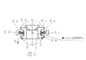
図7ないし図9は基本的な対物レンズ駆動装置の構成を示したもので、図7は従来の対物レンズ駆動装置の光ディスク接線方向の断面図、図8はその対物レンズ駆動装置の側面図、図9はその対物レンズ駆動装置の光ディスク半径方向の断面図である。
【0004】
対物レンズ1はレンズホルダ2上面に配置され、レンズホルダ2の側面にフォーカシングコイル3が巻回され、かつ、レンズホルダ2の側面にトラッキングコイル4および対物レンズ1を光ディスク半径方向に傾動駆動する傾動コイル9が貼付けられている。
【0005】
4本の平行な直線状の弾性支持部材8は、その一端をレンズホルダ2に、他端を固定部に固定され、対物レンズ1を支持しているレンズホルダ2はフォーカシング方向、トラッキング方向に移動可能で、かつ、光ディスク半径方向への傾動動作も可能になるように弾性支持されている。
【0006】
弾性支持部材8の一端が固定されている固定部に、ヨーク5とマグネット6から構成される磁気回路が配置され、前記フォーカシングコイル3、トラッキングコイル4および傾動コイル9を流れる駆動電流は、この磁気回路から発生される磁束に作用するように配置されている。対物レンズ1を支持しているレンズホルダ2の上面に、光ディスクの傾きを検出する傾き検出器7が配置されている。
【0007】
フォーカシング制御時は、光ディスク記録面の面振れに対応してフォーカシングコイル3に電流を適切に供給して対物レンズ1を光軸方向に動作させ、光ビームのスポットを光ディスク記録面上に追従させることができる。トラッキング制御時は、光ディスクのトラックの偏芯・蛇行に対応してトラッキングコイル4に適切に電流を供給して、対物レンズ1を光軸と直角方向に動作させ、光ビームのスポットを光ディスクのトラック上に追従させることができる。光ディスクの傾きに対しては、傾き検出器7からの信号を基に傾動コイル9に適切に電流を供給し、対物レンズ1を光ディスクの傾きに対応して傾動駆動させる。
【0008】
【発明が解決しようとする課題】
近年、光ディスク装置においては高記録密度化が進められている。高記録密度化を実現する一つの方法に光ビームをより細く絞り込み、光ディスクの記録面上でのスポット径を小さくする方法がある。このスポット径は、光ビームの波長をλ、対物レンズ1の開口数をNAとすると、(λ/NA)に比例する。
【0009】
そのため一般的には、光ビームの波長λを小さくし、かつ、対物レンズ1の開口数(NA)を従来よりも大きな値とすることにより光ビームを細く絞り込み、高記録密度化に対応する方法が主流となっている。対物レンズ1のNAを大きくすることにより、光ビームをより細く絞り込むことが可能となる反面、光ディスクと対物レンズ1との傾きによる光学特性の劣化は顕著になる。従って何らかの手段により、光ディスクと対物レンズ1との傾き角度を一定値以内に抑える必要がある。
【0010】
この対物レンズ駆動装置は、光ディスクと対物レンズ1との相対傾き角度を傾き検出器7で検出し、それに基づき傾動コイル9に適切に電流を供給することにより、対物レンズ1と光ディスクとの相対傾き角度を一定に保つように構成されていた。
【0011】
しかし、従来提案された発明では、各駆動コイルに供給する電流の通電手段について考慮されていない。また、一般的に導電性部材で構成されている弾性支持部材8は4本しかなく、この弾性支持部材8により電流を供給できるのは、最大2個の駆動コイルである。仮に、フォーカシングコイル3とトラッキングコイル4に対して弾性支持部材8を介して電流を供給すると、傾動コイル9には、特開平6−139600号公報にあるように傾動コイル9専用の引出し線が必要となる。しかし、この引出し線は、組立て作業性が悪く、かつ、対物レンズ1の動作傾き特性に与える悪影響が大きいため、光ディスク半径方向の傾動制御を行う高精度の対物レンズ駆動装置には不適当である。
【0012】
このように従来の対物レンズ駆動装置では各駆動コイルへの電流供給手段については考慮されていないため、4本の導電性弾性支持部材の他に引出し線等が必要となり、組立て作業性が悪く かつ、安定した動作特性を得られないという欠点があった。
【0013】
本発明は上記課題を解決するためになされたもので、各駆動コイルへの電流供給を導電性弾性支持部材にて行い、安定した動作特性を得られる傾動可能な対物レンズ駆動装置ならびにそれを用いた光ディスク装置を実現することを目的としている。
【0014】
【課題を解決するための手段】
上記目的を達成するため本発明の第1の手段は、光ビームを光ディスク上に集光させる対物レンズと、
該対物レンズをその光軸方向に駆動するための第1の駆動コイルと、
前記対物レンズをその光軸と直角方向に駆動するための第2の駆動コイルと、
前記対物レンズを前記光ディスク半径方向に傾動駆動する傾動駆動コイルと、
前記対物レンズを保持するレンズホルダと、
前記第1、第2の駆動コイル、傾動駆動コイルに対して磁束を発生させるためのマグネットと、
前記対物レンズ、レンズホルダ、第1、第2の駆動コイル、傾動駆動コイルを含む可動部に一端が固定されてその可動部を弾性支持すると共に第1、第2の駆動コイル、傾動駆動コイルにそれぞれ電流を供給する6本の導電性弾性支持部材と、
該弾性支持部材の他端を固定する固定部とを備え、
前記6本の導電性弾性支持部材が、前記可動部の対物レンズの光軸方向のほぼ中央に対し前記光ディスク側に4本、前記光ディスクとは反対側に2本、それぞれ配置され、
前記光ディスク側に配置された4本のうち2本の弾性支持部材の軸方向の剛性を、他の4本の弾性支持部材の軸方向の剛性よりも小さくしたことを特徴とするものである。
【0020】
本発明の第2の手段は、光ビームを光ディスク上に集光させるための対物レンズを駆動する対物レンズ駆動装置を備えた光ディスク装置において、前記対物レンズ駆動装置が請求項1記載の対物レンズ駆動装置であることを特徴とするものである。
【0023】
【発明の実施の形態】
以下、図面を用いて本発明の実施の形態について説明する。
図1、図2、図3は本発明による対物レンズ駆動装置の第1の実施形態を示した上面構成図、光ディスク接線方向の要部断面図(図1のA−A断面図)および光ディスク半径方向の要部断面図(図1のB−B断面図)である。
【0024】
これらの図において、対物レンズ1はレンズホルダ2の上面に配置され、レンズホルダ2の外周に対物レンズ1をほぼその巻中心としてフォーカシングコイル3が巻回されている。フォーカシングコイル3の光ディスク半径方向の両側に、傾動コイル9が配置されている。フォーカシングコイル3の光ディスク接線方向の外側にトラッキングコイル4がレンズホルダ2にかかるように配置されている。
【0025】
この対物レンズ1、レンズホルダ2、フォーカシングコイル3、トラッキングコイル4、傾動コイル9等から可動部が構成されている。可動部は6本の弾性支持部材8で支持され、弾性支持部材8の一端は可動部に、他端は固定部に固定されている。この弾性支持部材8は例えばベリリウム銅、リン青銅などの導電性材料で構成され、可動部に配置された前記フォーカシングコイル3、トラッキングコイル4、傾動コイル9と、それぞれ電気的に接続され、固定部から導電性弾性支持部材8を経由してフォーカシングコイル3、トラッキングコイル4、傾動コイル9にそれぞれ電流を供給することができる。
【0026】
この6本の弾性支持部材8は、図1および図3に示すように対物レンズ1の光軸方向において、光ディスク側に4本(8a、8b、8c、8d)、光ディスクと反対側に2本(8e、8f)配置されている。光ディスク側に配置された弾性支持部材の内2本(8a、8b)は、レンズホルダ2及び固定部に設けられたV字状の溝に、光ディスク側より配置、位置決めが可能である。
【0027】
弾性支持部材8a、8bのレンズホルダ2側の先端をL字状に曲げることにより、他の4本(8c、8d、8e、8f)から離れた位置での各コイルとの結線を可能にし、組立て作業性を向上させている。
【0028】
また図1に示すように、弾性支持部材8a、8bの一部にねじりバネ状部分を設け、軸方向の剛性を小さくすることにより、6本の弾性支持部材8による過剰拘束の悪影響を軽減し、安定した動作特性を得ることができる。
【0029】
前記弾性支持部材8の一端が固定されている固定部に、ヨーク5とマグネット6から構成される磁気回路が配置されている。トラッキングコイル4とフォーカシングコイル3の光ディスク接線方向外周部を挟むようにマグネット6a、6bとヨーク5から構成される磁気回路が2組配置され、それぞれその磁気ギャップ内にフォーカシングコイル3とトラッキングコイル4の有効線部分が位置するように構成されている。
【0030】
傾動駆動用に2個のマグネット6c、6dが可動部の光ディスク半径方向の外周部に配置され、マグネット6c、6dから出る磁束と前記傾動コイル9を流れる電流との作用により、傾動駆動力が発生するように構成されている。
【0031】
図示しないが、対物レンズ1の傾動動作は、光ディスクから読み取った信号からジッター量を算出し、このジッター量を小さくするように傾動駆動信号が生成する傾動駆動回路が設けられ、この傾動駆動回路からの信号により前記傾動コイル9に適切な駆動電流が供給されて、対物レンズ1の傾動動作が行なわれる。
【0032】
次にこの対物レンズ駆動装置の動作について説明する。
光ディスクの上下の面振れに対して、光ピックアップで光学的にフォーカシングエラー信号を作成し、この信号に応じてフォーカシング駆動回路からフォーカシングコイル3に適切な駆動電流が導電性弾性支持部材8を介して供給され、対物レンズ1により集光された光ビームの光スポットが、常に光ディスクの記録面上に位置するようにフォーカシング制御される。
【0033】
トラックの蛇行・偏芯に対しても、光ピックアップで光学的にトラッキングエラー信号を作成し、この信号に応じてトラッキング駆動回路からトラッキングコイル4に適切な駆動電流が導電性弾性支持部材8を介して供給され、光ビームの光スポットが常に光ディスクのトラック上に位置するようにトラッキング制御される。このようにしてフォーカシング制御とトラッキング制御が行なわれ、光ディスクから信号を読み取ることが可能となる。
【0034】
光ディスクから読み取った信号には、主に光ディスクと対物レンズ1との相対傾き角度により、その大きさが左右される時間軸方向の誤差(ジッター)が含まれている。従って、対物レンズ1を光ディスクの傾きに合わせて適切に傾けることにより、ジッター量を小さく抑えることができる。逆に、この読み取り信号に含まれるジッター量を算出し、ジッター量が最小になるように対物レンズ1の傾動駆動信号を作成し、この傾動駆動信号に応じて傾動コイル9に適切な傾動駆動電流を導電性弾性支持部材8を介して供給することにより、対物レンズ1の傾動制御(チルト制御)を行うことができる。
【0035】
しかし、傾動コイル9への通電の為に配置した弾性支持部材8は可動部を拘束する意味においては過剰拘束となる為、高度な取付精度を実現しなければ、安定した可動部の動作を確保できない。そこで本発明では、低い取付精度でも過剰拘束の影響を軽減できるよう5、6本目の弾性支持部材(8a、8b)の一部に、ねじりバネ状またはコイルバネ状部分を設けることにより軸方向の剛性を低下させ、安定した可動部の動作を可能としている。
【0036】
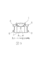
図4、図5、図6は本発明による対物レンズ駆動装置の第2の実施形態を示した上面構成図、光ディスク接線方向の要部断面図(図4のA−A断面図)、光ディスク半径方向の要部断面図(図4のB−B断面図)である。
【0037】
この実施形態において特徴的なのは、弾性支持部材8a、8bの可動部側での固定位置と固定部側での固定位置との距離(有効長)が、他の4本と異なっている点である。この構成により弾性支持部材8a、8bは、他の4本から離れた位置で、各コイルとの結線が可能で、組立て作業性を向上させている。
【0038】
しかしながら、前記可動部が弾性支持部材8c、8d、8e、8fを腕とした平行リンク機構として機能する場合、弾性支持部材8の内の2本(8a、8b)は、他の4本(8c、8d、8e、8f)と有効長が異なるため、安定した可動部の動作を確保することが困難となる。
【0039】
そこで弾性支持部材8a、8bの一部にコイルバネ状部を設け、弾性支持部材8a、8bの軸方向の剛性を小さくすることにより、6本の弾性支持部材8の有効長が異なっていても、安定した可動部の動作を可能としている。
【0040】
また、図6において6本の弾性支持部材8a〜8fは、可動部の重心位置または6本の弾性支持部材8a〜8fの支持中心位置を中心とした同一円周上に略一致するように配置されている。これにより可動部は、前記重心位置または前記支持中心位置を中心として傾動動作し、安定した傾動動作特性を得ることができる。
【0041】
【発明の効果】
本発明は以上説明した通り、対物レンズが配置された可動部を6本の導電性弾性支持部材で支持し、かつ、フォーカシングコイル、トラッキングコイル、傾動コイルを電気的に導電性弾性支持部材と接続し、この弾性支持部材を介して適切に各駆動電流を各コイルに供給することが可能となることにより、動作特性のバラツキの原因となる引出し線等の給電用部品が不要となり、安定した動作特性が得られる。
【0042】
その結果、フォーカシング制御およびトラッキング制御を動作させながら、対物レンズを光ディスク半径方向に傾動させ、最適な傾きに制御することが可能となり、光ディスクから、ジッターの小さい正確な信号の読み出し、書き込みが可能となる。
【図面の簡単な説明】
【図1】本発明による対物レンズ駆動装置の第1の実施形態を示した上面構成図である。
【図2】その対物レンズ駆動装置の光ディスク接線方向の要部断面図である。
【図3】その対物レンズ駆動装置の光ディスク半径方向の要部断面図である。
【図4】本発明による対物レンズ駆動装置の第2の実施形態を示した上面構成図である。
【図5】その対物レンズ駆動装置の光ディスク接線方向の要部断面図である。
【図6】その対物レンズ駆動装置の光ディスク半径方向の要部断面図である。
【図7】従来の対物レンズ駆動装置の光ディスク接線方向の断面図である。
【図8】その対物レンズ駆動装置の側面図である。
【図9】その対物レンズ駆動装置の光ディスク半径方向の断面図である。
【符号の説明】
1 対物レンズ
2 レンズホルダ
3 フォーカシングコイル
4 トラッキングコイル
5 ヨーク
6 マグネット
8、8a〜8f 弾性支持部材
9 傾動コイル[0001]
BACKGROUND OF THE INVENTION
The present invention relates to an objective lens driving device used in an optical disc apparatus, and more particularly to an elastic support member that elastically supports a movable portion including an objective lens, a drive coil, a lens holder, and the like.
[0002]
[Prior art]
As an example of an objective lens driving device used in an optical disk device, for example, those described in JP-A-6-251405 and JP-A-6-139600 are known.
[0003]
FIG. 7 to FIG. 9 show the configuration of a basic objective lens driving device, FIG. 7 is a cross-sectional view of the conventional objective lens driving device in the optical disk tangential direction, and FIG. 8 is a side view of the objective lens driving device. FIG. 9 is a cross-sectional view of the objective lens driving device in the radial direction of the optical disc.
[0004]
The
[0005]
The four parallel linear
[0006]
A magnetic circuit composed of a
[0007]
At the time of focusing control, current is appropriately supplied to the focusing
[0008]
[Problems to be solved by the invention]
In recent years, higher recording density has been promoted in optical disc apparatuses. One method for realizing high recording density is a method of narrowing the light beam to reduce the spot diameter on the recording surface of the optical disk. This spot diameter is proportional to (λ / NA) where λ is the wavelength of the light beam and NA is the numerical aperture of the
[0009]
For this reason, generally, a method for narrowing the light beam by reducing the wavelength λ of the light beam and setting the numerical aperture (NA) of the
[0010]
This objective lens driving device detects the relative tilt angle between the optical disk and the
[0011]
However, in the conventionally proposed invention, no consideration is given to the means for energizing the current supplied to each drive coil. In general, there are only four
[0012]
As described above, in the conventional objective lens driving device, the means for supplying current to each driving coil is not taken into consideration, so that a lead wire or the like is required in addition to the four conductive elastic support members, and the assembly workability is poor. There is a drawback that stable operating characteristics cannot be obtained.
[0013]
The present invention has been made in order to solve the above-described problems, and a tiltable objective lens driving device capable of obtaining a stable operating characteristic by supplying a current to each driving coil with a conductive elastic support member and using the same. The purpose is to realize the optical disc apparatus .
[0014]
[Means for Solving the Problems]
In order to achieve the above object, the first means of the present invention comprises an objective lens for condensing a light beam on an optical disc,
A first drive coil for driving the objective lens in the optical axis direction;
A second drive coil for driving the objective lens in a direction perpendicular to its optical axis;
A tilt drive coil that tilts and drives the objective lens in the radial direction of the optical disc;
A lens holder for holding the objective lens;
A magnet for generating a magnetic flux for the first and second drive coils and the tilt drive coil;
One end is fixed to the movable part including the objective lens, the lens holder, the first and second drive coils, and the tilting drive coil to elastically support the movable part, and the first and second drive coils and the tilting
A fixing portion for fixing the other end of the elastic support member ,
The six conductive elastic support members are arranged on the optical disc side with respect to the substantially center of the objective lens of the movable part in the optical axis direction, and two on the opposite side of the optical disc, respectively.
Of the four arranged on the optical disc side, the rigidity in the axial direction of two elastic support members is made smaller than the rigidity in the axial direction of the other four elastic support members .
[0020]
According to a second means of the present invention, there is provided an optical disk apparatus comprising an objective lens driving apparatus for driving an objective lens for condensing a light beam on the optical disk, wherein the objective lens driving apparatus is the objective lens driving apparatus according to
[0023]
DETAILED DESCRIPTION OF THE INVENTION
Hereinafter, embodiments of the present invention will be described with reference to the drawings.
1, 2, and 3 are a top view illustrating a first embodiment of an objective lens driving device according to the present invention, a cross-sectional view of a main part in a tangential direction of an optical disk (cross-sectional view taken along line AA in FIG. 1), and an optical disk radius. It is principal part sectional drawing (BB sectional drawing of FIG. 1) of a direction.
[0024]
In these drawings, the
[0025]
The
[0026]
As shown in FIGS. 1 and 3, four
[0027]
By bending the tip of the elastic support members 8a, 8b on the
[0028]
As shown in FIG. 1, the elastic support members 8a and 8b are provided with a torsion spring-like portion to reduce the axial rigidity, thereby reducing the adverse effect of excessive restraint by the six
[0029]
A magnetic circuit composed of a
[0030]
Two
[0031]
Although not shown, the tilting operation of the
[0032]
Next, the operation of the objective lens driving device will be described.
A focusing error signal is optically generated by an optical pickup with respect to the upper and lower surface vibrations of the optical disk, and an appropriate drive current is supplied from the focusing drive circuit to the focusing
[0033]
A tracking error signal is optically generated by the optical pickup even for the meandering / eccentricity of the track, and an appropriate drive current is supplied from the tracking drive circuit to the
[0034]
The signal read from the optical disk includes a time-axis direction error (jitter) whose magnitude depends mainly on the relative tilt angle between the optical disk and the
[0035]
However, the
[0036]
4, 5, and 6 are a top view illustrating a second embodiment of the objective lens driving device according to the present invention, a cross-sectional view of a main part in a tangential direction of the optical disk (cross-sectional view taken along line AA in FIG. 4), and a radius of the optical disk. It is principal part sectional drawing (BB sectional drawing of FIG. 4) of a direction.
[0037]
What is characteristic in this embodiment is that the distance (effective length) between the fixed position on the movable part side of the elastic support members 8a and 8b and the fixed position on the fixed part side is different from the other four. . With this configuration, the elastic support members 8a and 8b can be connected to the coils at positions apart from the other four, thereby improving the assembly workability.
[0038]
However, when the movable portion functions as a parallel link mechanism using the elastic support members 8c, 8d, 8e, and 8f as arms, two of the elastic support members 8 (8a and 8b) are replaced with the other four (8c , 8d, 8e, 8f) and the effective length are different, it is difficult to ensure a stable operation of the movable part.
[0039]
Therefore, even if the effective lengths of the six
[0040]
In FIG. 6, the six elastic support members 8 a to 8 f are arranged so as to substantially coincide on the same circumference with the center of gravity of the movable portion or the support center position of the six elastic support members 8 a to 8 f as the center. Has been. As a result, the movable portion tilts around the position of the center of gravity or the support center position, and stable tilting operation characteristics can be obtained.
[0041]
【The invention's effect】
In the present invention, as described above, the movable portion on which the objective lens is arranged is supported by six conductive elastic support members, and the focusing coil, tracking coil, and tilt coil are electrically connected to the conductive elastic support members. In addition, since each drive current can be appropriately supplied to each coil via this elastic support member, there is no need for power supply parts such as lead wires that cause variations in operating characteristics, and stable operation is achieved. Characteristics are obtained.
[0042]
As a result, it is possible to tilt the objective lens in the radial direction of the optical disc while operating focusing control and tracking control, and to control the tilt to the optimum, and to read and write accurate signals with low jitter from the optical disc. Become.
[Brief description of the drawings]
FIG. 1 is a top structural view showing a first embodiment of an objective lens driving device according to the present invention;
FIG. 2 is a cross-sectional view of the main part of the objective lens driving device in the tangential direction of the optical disc.
FIG. 3 is a cross-sectional view of a main part in the radial direction of the optical disk of the objective lens driving device.
FIG. 4 is a top structural view showing a second embodiment of the objective lens driving device according to the present invention;
FIG. 5 is a cross-sectional view of the main part of the objective lens driving device in the tangential direction of the optical disc.
FIG. 6 is a cross-sectional view of the main part of the objective lens driving device in the radial direction of the optical disc.
FIG. 7 is a sectional view of a conventional objective lens driving device in a direction tangent to an optical disc.
FIG. 8 is a side view of the objective lens driving device.
FIG. 9 is a sectional view of the objective lens driving device in the radial direction of the optical disc.
[Explanation of symbols]
DESCRIPTION OF
Claims (2)
該対物レンズをその光軸方向に駆動するための第1の駆動コイルと、
前記対物レンズをその光軸と直角方向に駆動するための第2の駆動コイルと、
前記対物レンズを前記光ディスク半径方向に傾動駆動する傾動駆動コイルと、
前記対物レンズを保持するレンズホルダと、
前記第1、第2の駆動コイル、傾動駆動コイルに対して磁束を発生させるためのマグネットと、
前記対物レンズ、レンズホルダ、第1、第2の駆動コイル、傾動駆動コイルを含む可動部に一端が固定されてその可動部を弾性支持すると共に第1、第2の駆動コイル、傾動駆動コイルにそれぞれ電流を供給する6本の導電性弾性支持部材と、
該弾性支持部材の他端を固定する固定部とを備え、
前記6本の導電性弾性支持部材が、前記可動部の対物レンズの光軸方向のほぼ中央に対し前記光ディスク側に4本、前記光ディスクとは反対側に2本、それぞれ配置され、
前記光ディスク側に配置された4本のうち2本の弾性支持部材の軸方向の剛性を、他の4本の弾性支持部材の軸方向の剛性よりも小さくしたことを特徴とする対物レンズ駆動装置。An objective lens for focusing the light beam on the optical disc;
A first drive coil for driving the objective lens in the optical axis direction;
A second drive coil for driving the objective lens in a direction perpendicular to its optical axis;
A tilt drive coil that tilts and drives the objective lens in the radial direction of the optical disc;
A lens holder for holding the objective lens;
A magnet for generating a magnetic flux for the first and second drive coils and the tilt drive coil;
One end is fixed to the movable part including the objective lens, the lens holder, the first and second drive coils, and the tilting drive coil to elastically support the movable part, and the first and second drive coils and the tilting drive coil 6 conductive elastic support members each supplying current,
A fixing portion for fixing the other end of the elastic support member ,
The six conductive elastic support members are arranged on the optical disc side with respect to the substantially center of the objective lens of the movable part in the optical axis direction, and two on the opposite side of the optical disc, respectively.
An objective lens driving device characterized in that two of the four elastic support members arranged on the optical disc side have an axial rigidity smaller than that of the other four elastic support members. .
Priority Applications (1)
| Application Number | Priority Date | Filing Date | Title |
|---|---|---|---|
| JP26913699A JP3658526B2 (en) | 1999-09-22 | 1999-09-22 | Objective lens driving device and optical disk device using the same |
Applications Claiming Priority (1)
| Application Number | Priority Date | Filing Date | Title |
|---|---|---|---|
| JP26913699A JP3658526B2 (en) | 1999-09-22 | 1999-09-22 | Objective lens driving device and optical disk device using the same |
Publications (3)
| Publication Number | Publication Date |
|---|---|
| JP2001093177A JP2001093177A (en) | 2001-04-06 |
| JP2001093177A5 JP2001093177A5 (en) | 2004-11-25 |
| JP3658526B2 true JP3658526B2 (en) | 2005-06-08 |
Family
ID=17468202
Family Applications (1)
| Application Number | Title | Priority Date | Filing Date |
|---|---|---|---|
| JP26913699A Expired - Lifetime JP3658526B2 (en) | 1999-09-22 | 1999-09-22 | Objective lens driving device and optical disk device using the same |
Country Status (1)
| Country | Link |
|---|---|
| JP (1) | JP3658526B2 (en) |
Families Citing this family (14)
| Publication number | Priority date | Publication date | Assignee | Title |
|---|---|---|---|---|
| KR100436720B1 (en) * | 2001-08-28 | 2004-06-22 | 삼성전기주식회사 | Optical pick-up actuator |
| JP2003109234A (en) | 2001-09-28 | 2003-04-11 | Teac Corp | Optical pickup device |
| KR100881666B1 (en) | 2002-07-09 | 2009-02-06 | 삼성전자주식회사 | Objective lens driving apparatus for optical pickup |
| JP2004145989A (en) | 2002-10-25 | 2004-05-20 | Matsushita Electric Ind Co Ltd | Objective lens drive unit |
| JP3821105B2 (en) | 2003-02-28 | 2006-09-13 | 三菱電機株式会社 | Optical means driving device |
| JP2005038537A (en) | 2003-07-17 | 2005-02-10 | Mitsumi Electric Co Ltd | Objective lens driving device |
| JP2005158161A (en) * | 2003-11-26 | 2005-06-16 | Mitsumi Electric Co Ltd | Objective lens driving apparatus |
| US7428112B2 (en) | 2003-12-19 | 2008-09-23 | Mitsumi Electric Co., Ltd. | Objective lens driving device having damper portions capable of obtaining a moderate damping effect |
| JPWO2005096287A1 (en) | 2004-03-30 | 2008-07-31 | パイオニア株式会社 | Pickup actuator, pickup device, recording medium drive device, and method for manufacturing pickup actuator |
| JPWO2005096288A1 (en) * | 2004-03-30 | 2008-07-31 | パイオニア株式会社 | Pickup actuator, pickup device, recording medium driving device, and method for manufacturing pickup actuator |
| JP2006065971A (en) | 2004-08-27 | 2006-03-09 | Mitsumi Electric Co Ltd | Optical pickup |
| JP2006066013A (en) | 2004-08-30 | 2006-03-09 | Mitsumi Electric Co Ltd | Objective lens holder and objective lens driving device |
| JP2006066016A (en) | 2004-08-30 | 2006-03-09 | Mitsumi Electric Co Ltd | Objective lens driving device |
| JP4693510B2 (en) * | 2005-06-08 | 2011-06-01 | 三洋電機株式会社 | Objective lens drive |
-
1999
- 1999-09-22 JP JP26913699A patent/JP3658526B2/en not_active Expired - Lifetime
Also Published As
| Publication number | Publication date |
|---|---|
| JP2001093177A (en) | 2001-04-06 |
Similar Documents
| Publication | Publication Date | Title |
|---|---|---|
| JP3658526B2 (en) | Objective lens driving device and optical disk device using the same | |
| KR20010093031A (en) | Optical pick up actuator | |
| US7697381B2 (en) | Object lens drive unit | |
| JPWO2005112012A1 (en) | Optical pickup and optical disk device | |
| KR20030009197A (en) | Actuator apparatus for optical pickup having tilt control | |
| JP2000149292A (en) | Objective lens drive device | |
| JP3675356B2 (en) | Objective lens drive | |
| JP3323699B2 (en) | Objective lens drive | |
| JPWO2003098614A1 (en) | Objective lens drive | |
| JPH11306570A (en) | Object lens driving device | |
| JP3550547B2 (en) | Objective lens drive | |
| JP2000067444A (en) | Objective lens driving device | |
| KR20010091975A (en) | Objective lens drive apparatus | |
| JPH11316963A (en) | Optical pickup | |
| JP3875168B2 (en) | Objective lens driving device and information recording / reproducing device | |
| JP4533200B2 (en) | Objective lens drive device, optical pickup device, and optical disk drive device | |
| KR20010038040A (en) | Optical pickup assembly | |
| JP2002352456A (en) | Optical head device | |
| JP2001014696A (en) | Objective lens drive assembly | |
| KR20080009316A (en) | Optical pickup unit for a disk drive and disk drive comprising such an optical pickup unit | |
| JP3983149B2 (en) | Optical pickup objective lens drive device | |
| JP2005018837A (en) | Objective lens driving device | |
| JP2726584B2 (en) | Objective lens drive | |
| JPH05266503A (en) | Optical head | |
| JP2001184686A (en) | Objective lens driving device |
Legal Events
| Date | Code | Title | Description |
|---|---|---|---|
| A977 | Report on retrieval |
Free format text: JAPANESE INTERMEDIATE CODE: A971007 Effective date: 20040716 |
|
| A131 | Notification of reasons for refusal |
Free format text: JAPANESE INTERMEDIATE CODE: A131 Effective date: 20040727 |
|
| A521 | Written amendment |
Free format text: JAPANESE INTERMEDIATE CODE: A523 Effective date: 20040924 |
|
| TRDD | Decision of grant or rejection written | ||
| A01 | Written decision to grant a patent or to grant a registration (utility model) |
Free format text: JAPANESE INTERMEDIATE CODE: A01 Effective date: 20050308 |
|
| A61 | First payment of annual fees (during grant procedure) |
Free format text: JAPANESE INTERMEDIATE CODE: A61 Effective date: 20050314 |
|
| R150 | Certificate of patent or registration of utility model |
Ref document number: 3658526 Country of ref document: JP Free format text: JAPANESE INTERMEDIATE CODE: R150 Free format text: JAPANESE INTERMEDIATE CODE: R150 |
|
| FPAY | Renewal fee payment (event date is renewal date of database) |
Free format text: PAYMENT UNTIL: 20090318 Year of fee payment: 4 |
|
| R250 | Receipt of annual fees |
Free format text: JAPANESE INTERMEDIATE CODE: R250 |
|
| FPAY | Renewal fee payment (event date is renewal date of database) |
Free format text: PAYMENT UNTIL: 20090318 Year of fee payment: 4 |
|
| FPAY | Renewal fee payment (event date is renewal date of database) |
Free format text: PAYMENT UNTIL: 20100318 Year of fee payment: 5 |
|
| R250 | Receipt of annual fees |
Free format text: JAPANESE INTERMEDIATE CODE: R250 |
|
| FPAY | Renewal fee payment (event date is renewal date of database) |
Free format text: PAYMENT UNTIL: 20110318 Year of fee payment: 6 |
|
| FPAY | Renewal fee payment (event date is renewal date of database) |
Free format text: PAYMENT UNTIL: 20110318 Year of fee payment: 6 |
|
| FPAY | Renewal fee payment (event date is renewal date of database) |
Free format text: PAYMENT UNTIL: 20120318 Year of fee payment: 7 |
|
| FPAY | Renewal fee payment (event date is renewal date of database) |
Free format text: PAYMENT UNTIL: 20130318 Year of fee payment: 8 |
|
| FPAY | Renewal fee payment (event date is renewal date of database) |
Free format text: PAYMENT UNTIL: 20130318 Year of fee payment: 8 |
|
| FPAY | Renewal fee payment (event date is renewal date of database) |
Free format text: PAYMENT UNTIL: 20140318 Year of fee payment: 9 |
|
| S531 | Written request for registration of change of domicile |
Free format text: JAPANESE INTERMEDIATE CODE: R313531 |
|
| R350 | Written notification of registration of transfer |
Free format text: JAPANESE INTERMEDIATE CODE: R350 |
|
| EXPY | Cancellation because of completion of term |