JP3656857B2 - Full-motion video NTSC display device and method - Google Patents
Full-motion video NTSC display device and method Download PDFInfo
- Publication number
- JP3656857B2 JP3656857B2 JP28179294A JP28179294A JP3656857B2 JP 3656857 B2 JP3656857 B2 JP 3656857B2 JP 28179294 A JP28179294 A JP 28179294A JP 28179294 A JP28179294 A JP 28179294A JP 3656857 B2 JP3656857 B2 JP 3656857B2
- Authority
- JP
- Japan
- Prior art keywords
- sprite
- buffer
- cache
- scene
- objects
- Prior art date
- Legal status (The legal status is an assumption and is not a legal conclusion. Google has not performed a legal analysis and makes no representation as to the accuracy of the status listed.)
- Expired - Fee Related
Links
Images


Classifications
-
- G—PHYSICS
- G09—EDUCATION; CRYPTOGRAPHY; DISPLAY; ADVERTISING; SEALS
- G09G—ARRANGEMENTS OR CIRCUITS FOR CONTROL OF INDICATING DEVICES USING STATIC MEANS TO PRESENT VARIABLE INFORMATION
- G09G5/00—Control arrangements or circuits for visual indicators common to cathode-ray tube indicators and other visual indicators
- G09G5/42—Control arrangements or circuits for visual indicators common to cathode-ray tube indicators and other visual indicators characterised by the display of patterns using a display memory without fixed position correspondence between the display memory contents and the display position on the screen
-
- G—PHYSICS
- G06—COMPUTING; CALCULATING OR COUNTING
- G06T—IMAGE DATA PROCESSING OR GENERATION, IN GENERAL
- G06T13/00—Animation
-
- G—PHYSICS
- G09—EDUCATION; CRYPTOGRAPHY; DISPLAY; ADVERTISING; SEALS
- G09G—ARRANGEMENTS OR CIRCUITS FOR CONTROL OF INDICATING DEVICES USING STATIC MEANS TO PRESENT VARIABLE INFORMATION
- G09G5/00—Control arrangements or circuits for visual indicators common to cathode-ray tube indicators and other visual indicators
- G09G5/36—Control arrangements or circuits for visual indicators common to cathode-ray tube indicators and other visual indicators characterised by the display of a graphic pattern, e.g. using an all-points-addressable [APA] memory
- G09G5/39—Control of the bit-mapped memory
- G09G5/393—Arrangements for updating the contents of the bit-mapped memory
-
- G—PHYSICS
- G09—EDUCATION; CRYPTOGRAPHY; DISPLAY; ADVERTISING; SEALS
- G09G—ARRANGEMENTS OR CIRCUITS FOR CONTROL OF INDICATING DEVICES USING STATIC MEANS TO PRESENT VARIABLE INFORMATION
- G09G5/00—Control arrangements or circuits for visual indicators common to cathode-ray tube indicators and other visual indicators
- G09G5/36—Control arrangements or circuits for visual indicators common to cathode-ray tube indicators and other visual indicators characterised by the display of a graphic pattern, e.g. using an all-points-addressable [APA] memory
- G09G5/39—Control of the bit-mapped memory
- G09G5/399—Control of the bit-mapped memory using two or more bit-mapped memories, the operations of which are switched in time, e.g. ping-pong buffers
-
- Y—GENERAL TAGGING OF NEW TECHNOLOGICAL DEVELOPMENTS; GENERAL TAGGING OF CROSS-SECTIONAL TECHNOLOGIES SPANNING OVER SEVERAL SECTIONS OF THE IPC; TECHNICAL SUBJECTS COVERED BY FORMER USPC CROSS-REFERENCE ART COLLECTIONS [XRACs] AND DIGESTS
- Y10—TECHNICAL SUBJECTS COVERED BY FORMER USPC
- Y10S—TECHNICAL SUBJECTS COVERED BY FORMER USPC CROSS-REFERENCE ART COLLECTIONS [XRACs] AND DIGESTS
- Y10S345/00—Computer graphics processing and selective visual display systems
- Y10S345/949—Animation processing method
- Y10S345/95—Sprite processing
Description
【0001】
【産業上の利用分野】
本願発明はコンピュータ装置でのデータ処理に関するものであり、特にフルモーション動画表示装置及び方法に関するものである。
【0002】
【従来の技術】
図形出力表示装置への表示用画素データを記録するフレームバッファーと呼ばれているメモリー領域が多くのコンピュータ装置に用いられている。フレームバッファーに記録されている画素データを表示するため、表示制御装置はフレームバッファーに記録されている画素データを行単位で読み出し、デジタル・アナログ変換器(DAC)で画素データをアナログ映像信号に変換し、このアナログ映像信号を出力表示装置へ送信する。通常、この行単位走査は表示スクリーンの上側左隅に相当するフレームバッファーの領域から開始し、下側右隅まで継続的に走査する。
【0003】
一般に、フレームバッファーは複数の映像ランダムアクセスメモリー(VRAM)デバイスで構成されている。アクセスポートが1つしかない従来のダイナミックランダムアクセスメモリー(DRAM)デバイスとは異なりVRAMには2つのアクセスポートが設けられている。これら2つのアクセスポートのうち第1のアクセスポートはランダムアクセスポートと呼ばれ、VRAMに対して従来のランダムアクセスが行えるようになっているためVRAMに接続されている中央演算処理装置(CPU)はVRAM内のどの記憶領域に対しても読み出しまたは書き込み処理を行うことが可能である。一方、第2のアクセスポートはシリアルアクセスポートと呼ばれ、VRAMに対して同時シリアルアクセスを行えるようになっているためこのシリアルポートに接続されているデバイスはVRAMとシフトデータをやりとりできる。表示回路はこのシリアルポートにアクセスして出力表示装置を制御している回路へ画素データを供給する。このような回路構成であれば、CPUは画素データを表示回路から出力表示装置へ絶えず供給しながらVRAMへ書き込みを行うことができる。
【0004】
フレームバッファーに基づいたこの種の表示装置と表示スクリーンとを接続するコンピュータ装置の内部で動画シーケンスを作成する場合がある。このような装置で動画シーケンスを作成する場合、画像ソフトウェアで作成される一連のフレームの各フレームの画像はわずかながら変化する。動きが滑らかになるよう、1秒間に約15ー30個の割合で新規フレームを表示する。第1フレームの画像が次のフレームの画像に変化すると、連続して動作しているような効果が得られる。従って、フレームバッファーを連続的に更新すればフルモーション動画シーケンスが作り出させる。
【0005】
しかしながら、受取ると同時に出力表示装置へ画素データを転送するといったフレームバッファーの能力がある種の問題の原因になっている。フレームバッファーメモリーの画像を表示制御装置で走査している最中に動画ソフトウェアがフレームバッファーメモリーに書き込みを行うと、複数の動画フレームから図形イメージが同時に出力表示装置に表示されることがある。1以上の動画フレームから画素データが誤って表示される現象を「フレーム崩れ」(frame tear)と呼んでいる。フレームからフレームへの移り変わりによって表示装置に表示中の図形画像に歪みが発生するとこのフレーム崩れ現象は特に目立つ。
【0006】
このフレーム崩れ現象を防ぐため、二重バッファー処理表示装置を用いたコンピュータ装置もある。この二重バッファー処理表示装置では、フレームバッファーに2つのメモリー領域を設けて各メモリー領域にDAC回路へ送る画素データを格納する。第1のメモリー領域から出力表示装置へ第1動画フレームが出力されるため、表示スクリーンへの出力のため走査を行っている期間は第1メモリー領域は更新されない。第1メモリー領域が表示スクリーンに表示されている間は、動画ソフトウェアは第2メモリー領域に次の動画フレームを作成する。動画ソフトウェアが次の動画フレームを作成し終わるとDACが切り換えを行うためメモリーの第2領域が表示フレームになり、一方、メモリーの第1領域は「作業」領域になる。動画ソフトウェアは、メモリーの作業領域に次の動画フレームを作成する。このように、表示スクリーンに画素データを出力中のメモリー領域へ画素データが書き込まれることがないため二重バッファー処理表示装置ではフレームティア崩れ現象は発生しない。
【0007】
二重バッファー処理表示装置を用いてコンピュータ装置が動画シーケンスを作成する場合、CPUは作業領域に動画シーケンスの各新規動画フレーム毎にシーンを生成する。動画シーンは背景シーンと動画オブジェクトで構成してもよい。背景シーン上に動画オブジェクトを表示中であれば、動画オブジェクトを表示する前にCPUは背景シーン全体を生成しなくてはならない。高品質リアルタイム動画を行うには、動画フレーム用の背景と動画オブジェクトを1秒間に約15ー30回表示する必要がある。
【0008】
【発明が解決しようとする課題】
NTSC(National Television Standards Committee) 式解像度フレームバッファーでフルモーション動画を行うには、NTSC式解像度フレームバッファーの大きさに基づいてフレーム毎に約345,600画素を更新しなくてはならない。動画の各フレームは単一のスクリーンであり、このスクリーンは345,600(720x480)個の画素から出来ている。このように、1秒間に30コマの速度でフルモーション動画を表示するには、1秒間に10.368x10⁶(720x480x30)個の画素をフレームバッファーにコピーしなくてはならない。通常の縮小命令セットコンピュータ(RISC)CPUでは10MIPS(毎秒100万個)の命令を実行する。このようなRISC CPUの場合、NTSC式解像度フルモーション動画を表示するには各画素(10MIPS/10m画素)を描くのに約1個の命令を用いることができる。また、1画素につき何個の命令を用いることができるのかといった演算には積層画像データは考慮されていない。この画像データは、半透明の画像を複数生成して各フレームの最終画像を形成する場合に書き込みしなくてはならない場合がある。この種の動画は専用ハードウェアがないと実現不可能である。従って、専用コンピュータハードウェアを用いずにNTSC式解像度フルモーション動画が生成できるのが望ましい。
【0009】
本願発明は、このような要望に基づきなされたものであり、その目的は専用ハードウェアを用いずにNTSC式解像度フルモーション動画を1秒間に30コマ作成できる動画表示方法および装置を提供することにある。
【0010】
【課題を解決するための手段】
上記目的を達成するため、本願発明の動画表示方法は、中央演算処理装置(CPU)、メモリーおよび出力表示装置からなり、前記メモリーはバックバッファー、キャッシュバッファー、フロントバッファーから構成されているコンピュータ装置用動画表示方法であって、当該動画表示方法は、
前記表示装置出力用の水平、垂直、奥行きの属性からそれぞれなる複数のスプライトオブジェクトで構成されたスプライトリストを前記動画の各シーン毎に生成するステップと、
前記奥行き属性に基づいて各スプライトリストの前記スプライトオブジェクトを配列するステップと、
前回のシーンの前記スプライトオブジェクトと現在のシーンのスプライトオブジェクトを比較してどのスプライトオブジェクトが変化したのかを判断するステップと、
前回のフレームから現在のフレームまでで変化していないスプライトオブジェクトを全て含むよう前記キャッシュバッファーを更新するステップと、
前記キャッシュバッファーに記憶されている前記スプライトオブジェクトを前記バックバッファーへコピーするステップと、
現在のスプライトリストで判別されたスプライトオブジェクトが前記キャッシュバッファーにない時に前記奥行きの順番で前記バックバッファーへスプライトオブジェクトを追加するステップと、
前記バックバッファーと前記フロントバッファーを切り換えて現在のフレーム用のスプライトオブジェクトを前記出力表示装置に表示するステップとからなることを特徴とする。
【0011】
さらに、出力表示装置にフルモーション動画を表示する本願発明の装置は、
キャッシュバッファーと、
表示の前に動画シーンを記憶するバックバッファーと、
前記出力表示装置に接続されており、前記出力表示装置に表示中の動画シーンを記憶するフロントバッファーと、
前記動画の各シーン用のスプライトリストを生成するものであり、複数のスプライトオブジェクトから構成されたスプライトリスト生成手段であって、当該スプライトオブジェクトはそれぞれ前記出力表示装置へ表示するための水平、垂直、奥行き属性からなっており、前記奥行き属性に基づいて各スプライトリストの前記スプライトオブジェクトを配列するスプライトリスト生成手段と、
前回のシーンの前記スプライトオブジェクトと現在のシーンのスプライトオブジェクトを比較してどのスプライトオブジェクトが変化したのかを判断する手段と、
前記比較手段と前記キャッシュバッファーに接続されており、前回のシーンから現在のシーンまでで変化していないスプライトオブジェクトを全て記憶するキャッシュバッファー更新手段と、
前記キャッシュバッファーに記憶されている前記スプライトオブジェクトを前記バックバッファーにコピーし、また、現在のスプライトリストで判別されたスプライトオブジェクトが前記キャッシュバッファーにない時に前記奥行きの順番に前記バックバッファーにスプライトオブジェクトを追加するコピー手段と、
前記フロントおよびバックバッファーに接続されて前記バックバッファーと前記フロントバッファーを切り換えて現在のフレーム用のスプライトオブジェクトを前記出力表示装置に表示する切り換え手段とから構成されていることを特徴とする。
【0012】
【作用および効果】
本願発明の動画表示装置および方法は上記のような構成をしており、専用出力表示ハードウェアを用いずにスプライトオブジェクトで1秒間に30コマの速度でフルモーション動画映像を表示する。各スプライトオブジェクトは、出力表示装置上のある位置にスプライトオブジェクトを写像するための水平(X),垂直(Y)、奥行き(Z)の属性から構成されている。対応する動画フレームを定義する一連のスプライトオブジェクトが納められているスプライトリストを動画シーケンスのフレーム毎に生成する。動画を表示するため、スプライトリストのスプライトオブジェクトのX,Y,Z属性を変化させる。
【0013】
フルモーション動画を実現するため、コンピュータ装置に内蔵されているメインメモリーは中央演算処理装置(CPU)に接続されている。このコンピュータ装置には3つの物理的メモリー領域が設けられており、これらのメモリー領域にはフロントバッファー、バックバッファー、キャッシュバッファーの状態がそれぞれ任意的かつ動的に割り当てられている。フロントバッファー、バックバッファー、キャッシュバッファーは、対応する出力表示装置の解像度奥行きカラー能力にあった全く同じ大きさのラスタをそれぞれ備えている。バックバッファーとフロントバッファーは映像信号デジタル・アナログ変換器(DAC)に接続されており、また、この映像信号DACは出力表示装置に接続されている。フルモーション動画映像のフレームを表示するため、フロントバッファーあるいはバックバッファーのいずれかのバッファーを選択するようCPUはDACをプログラムする。
【0014】
キャッシュバッファーとバックバッファーを初期化するため、動画シーケンス用初期フレームをキャッシュバッファーで描き、このフレームをバックバッファーにコピーする。次ぎにフロントバッファーとバックバッファーを切り換えて第1フレームを表示する。第2フレームを生成するため、第1フレームのスプライトオブジェクトを第2フレームのスプライトオブジェクトと比較して移動したスプライトオブジェクトがどれであるかを判断させる。移動スプライトオブジェクトが発見されるまでに見つかった静止スプライトオブジェクトは全てキャッシュバッファーに書き込まれる。キャッシュリミットは、キャッシュバッファーに記憶されているスプライトオブジェクトを判別するよう設定されている。次にこのキャッシュバッファーをバックバッファーにコピーし、バックバッファーとフロントバッファーを切り換えて第2フレームを表示する。
【0015】
続くフレームのそれぞれについて、現在のフレームのスプライトオブジェクトと前回のフレームのスプライトオブジェクトを比較してどのスプライトオブジェクトが移動したのかを判断する。変化したスプライトオブジェクトが検出され、また、キャッシュバッファーの内容が有効であれば、キャッシュバッファーをバックバッファーにコピーし、変化したスプライトオブジェクトをバックバッファーに書き込む。あるいは、変化したスプライトオブジェクトが検出され、キャッシュバッファーの内容が無効の場合は、キャッシュバッファーは書き直されてバックバッファーへコピーされる。変化したスプライトオブジェクトはバックバッファーに書き込まれ、フロントバッファーとバックバッファーが切り換えられる。
【0016】
【実施例】
表記方法および用語
以下に述べる詳細な説明は、主としてコンピュータ装置におけるアルゴリズムおよび処理の記号表示で行っている。これらのアルゴリズムおよび表示はデータ処理に精通した人が用いる手段であり、当該技術分野に精通した他の者に作業内容を伝える上で最も効率的な手段である。
【0017】
本願明細書においては、また一般に、アルゴリズムとは所望の結果を導くための一貫性のある一連の工程であると考えられている。これらの工程では物理量を物理的に操作する必要がある。必ずと言うわけではないが、これらの物理量は記憶、転送、結合、比較あるいは操作などを行うことが可能な電気または磁気信号の形をしているのが一般的である。共通した利用が行えるためこれらの信号をビット、値、要素、記号、文字、項、数字などと称するのが便利な場合もある。しかし、これらの用語あるいはその他類似の用語は全て適切な物理量に関連したもので、物理量に付与した便利なラベルにすぎないという点は念頭においておく必要がある。
【0018】
さらに、実行される演算を加算または比較などといった言葉で言及する場合もあるが、これらは人間のオペレーターが頭の中で行う演算に関連したものである。しかし、本願発明の一部である当該明細書記載の演算ではこのようなオペレーターの能力は必要でなく、ほとんどの場合は不要である。すなわち、演算とは機械的な演算である。本願発明の演算を実行する装置としては汎用デジタルコンピュータやその他類似のデバイスが役に立つ。どのような場合でも、コンピュータを作動させる時の演算方法と、演算それ自体の方法は常に区別する。本願発明は、コンピュータを作動させて電気的物理信号等(例えば、機械的あるいは化学的信号)を処理して他の所望の物理的信号を生成する方法に関するものである。
【0019】
本願発明はこれらの演算を実行する装置に関するものでもある。当該演算装置は必要な目的のための専用コンピュータとして構成したり、あるいは、格納されているコンピュータプログラムで選択的に起動させたりあるいは再構築したりする汎用コンピュータとして構成することも可能である。本質的には本願明細書に記載されているアルゴリズムは特定のコンピュータや他の装置に関連したものではない。特に、本願発明に開示されている教示内容に従って作成さいたプログラムを用いればとのような汎用コンピュータでも使用することができ、また、必要な工程を実行する専用装置を構成すればもっと便利になるかもしれない。これら様々な装置に必要な構成は、以下に述べる説明に示してある。本願発明の機能を実行可能な装置としては、FirstPerson社製の装置や他社のコンピュータ装置がある。
【0020】
以下図面を参照しながら本願発明の実施例を詳細に説明する。
【0021】
以下の説明では、本願発明が十分に理解できるよう説明のため特定の用語を使用している。当該技術分野の者には自明なことであるが、この用語は本願発明を実施には必要ではない。また、本願発明が不必要に不明確になるのを防ぐため周知な回路や装置はブロック図で示している。
【0022】
本願発明の方法および装置ではフルモーション動画をリアルタイムに表示することが可能である。本願発明の好適な実施例では、フルモーション動画をカラーテレビジョン標準方式選定委員会(NTSC)映像方式で生成および表示する。本願発明の方法および装置は、赤、緑、青(RGB)で作成した動画シーケンスや白黒映像方式にも適用できる。さらに、これらの方法と装置は高品位テレビ(HDTV)方式で生成した動画シーケンスにも適用することができる。NTSC映像方式に合った動画シーケンスは既存のテレビ方式に直接インターフェースすることが可能である。後でより詳細に説明するように、本願発明では専用出力表示ハードウェアを用いずに1秒間に30コマの速度でNTSC式解像度フルモーション動画映像を表示する。
【0023】
本願発明では、フルモーション動画表示用のスプライトオブジェクトを作成する。ビデオゲームアプリケーションによっては、ハードウェアに基づく動画技術でスプライトを用いたものもある。ハードウェア動画技術で使用できるハードウェアスプライトの数には限りがあり、このため動画シーケンスの表示も限られてしまう。また、ハードウェアスプライトは一定のレジスタサイズに限られているため全てのスプライトが同じ数の画素で構成されることになる。本願発明では、スプライトオブジェクトは図形イメージとして定義されており、この図形イメージはメモリーに格納されておりフルモーション動画の作成に使用される。本願発明のスプライトオブジェクトは特定の出力表示装置の大きさに限定されることはなく、スプライトオブジェクトはそれぞれ別の画素解像度で構成することが可能である。例えば、画素で構成されたスクリーン全体と同じ大きさになるよう背景イメージを含むスプライトオブジェクトを構成してもよい。
【0024】
スプライトオブジェクトは、出力表示装置上のある位置にスプライトオブジェクトを写像するための水平(X),垂直(Y),奥行き(Z)の属性をそれぞれ備えている。各スプライトオブジェクトのX、Y属性はそれぞれ水平、垂直出力表示位置を定義する。Z属性は特定のスプライトオブジェクトの積み重ね順序あるいは奥行きの深さを定義する。説明および取り決めのため、Z属性値が大きなスプライトオブジェクトをZ属性値が小さなスプライトオブジェクトの上に表示する。本願発明では、スプライトリストは動画シーケンスのフレーム毎に生成される。このスプライトリストには対応する動画フレームを定義する一連のスプライトオブジェクトが納められている。典型的な動画シーケンスを生成するには、背景イメージが含まれているスプライトオブジェクトを複数表示する。背景イメージを含んだスプライトオブジェクトの表示の他にキャラクターを決定するスプライトオブジェクトまたは動画シーケンス用ターゲットオブジェクトを表示する。動画フレームの前景にはキャラクタースプライトオブジェクトを表示するのが一般的である。動画を生成するにはスプライトオブジェクトのX,Y,Zの属性を変化させる。こうすると、スプライトオブジェクトの位置が移動もしくは変化してフルモーション動画が生成される。Z属性に基づくスプライトオブジェクトの順番を納めたスプライトリストの使用についてさらに詳細に説明する。
【0025】
図1は本願発明の第1実施例のコンピュータ装置のブロック図である。フルモーション動画を実現するため、コンピュータ装置50にはメインメモリー100が設けられている。このメインメモリー100はダイナミックランダムアクセスメモリー(DRAM)で構成するのが好ましい。メインメモリー100を中央演算処理装置(CPU)108に接続し、この中央演算処理装置108をさらにバス110に接続する。メインメモリー100にはコンピュータ装置50の一般的な処理のための記憶領域が設けられている。メインメモリー100にはこの他に本願発明のフルモーション動画を生成するための記憶領域も設けられている。メインメモリー100の一部は、キャッシュバッファー102、スプライトオブジェクト104、スプライトオブジェクト格納背景スプライト106で構成されている。キャッシュバッファー、スプライトオブジェクト104、背景スプライト106はメインメモリー100の中のいずれの領域に常駐させてもよい。コンピュータ装置50は3つの物理的なメモリー領域が設けられており、これらのメモリー領域にはフロントバッファー、バックバッファー、キャッシュバッファーの状態が任意的かつ動的に割り当てられている。フロントバッファー、バックバッファー、キャッシュバッファーには、対応する出力表示装置の解像度奥行きカラーの能力に合った全く同じ大きさのラスタがそれぞれに付与されている。バックバッファー112とフロントバッファー114は映像ランダムアクセスメモリー(VRAM)で実現する。バックバッファー112とフロントバッファー114は映像デジタル・アナログ変換器(DAC)116に接続されている。この映像DAC116は出力表示装置118に接続されている。
【0026】
フロントバッファー114とバックバッファー112はコンピュータ装置50のフレームバッファーとして作動する。フロントバッファー114とバックバッファー112には一連の走査線が格納されており、これらの走査線は出力表示装置118に表示するイメージを表している。映像DAC116はフロントバッファー114またはバックバッファー112を1行づつ走査し、画素走査線をアナログ方式に変換し、ラスタ出力表示装置118を駆動して関連する走査線を表示する。この出力表示装置118は陰極線管(CRT)または液晶ディスプレイ(LCD)出力表示装置で構成してもよい。画素すなわち絵素は出力表示装置118に照射された単一の着色ドットであり、フレームバッファーでは任意の番号で表される。例えば、24ビットの画素はそれぞれ8ビットの赤、緑、青の色で形成できる。16ビットの画素の場合、5ビットの赤、6ビットの緑、5ビットの青色で形成してもよい。コンピュータ装置は画素の他に文字(alpha) も記憶する。文字とは固定小数点であり、この小数点は各画素の不透明度を表しており、関連する画素データと1対1に対応する独立物理メモリーに格納してもよい。あるいは、画素データを備えた物理フレームバッファー内の単語として文字値をまとめることもできる。画素格納する方式であればどんな方式でもフルモーション動画の生成で使用することができる。
【0027】
フルモーション動画映像のフレームを表示するには、フロントバッファー114かバックバッファー112のいずれか1つを選択するようCPU108でDAC116をプログラムする。CPU108はフロントバッファー114とバックバッファー112を交互に選択する。説明のため、画素データを供給するよう現在選択されているVRAMをフロントバッファーとし、画素データ選択をするよう選択されていないVRAMをバックバッファーとする。この取り決めに従い、フロントバッファーは出力表示装置118に表示されているフレーム毎にVRAM114とVRAM112で切り替わる。対応するDACと出力ラスタ表示装置を用いたVRAMの動作は当該技術分野では周知であるためこれ以上の説明は省略する。
【0028】
図2は本願発明の第2実施例のコンピュータ装置のブロック図である。コンピュータ装置200は、キャッシュバッファーの配列が相違する点を除けば図1のコンピュータ装置50と同じ構成である。コンピュータ装置200では、キャッシュバッファー125はVRAMで実現している。図2のキャッシュバッファー用VRAMを用いてキャッシュバッファー125からバックバッファー112へのデータ転送を最適化する。キャッシュバッファー125からバックバッファーVRAM112への最適コピー動作についてより詳細に説明する。
【0029】
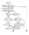
図3は本願発明のフルモーション動画表示方法を説明したフロー図である。フルモーション動画映像を表示するにはスプライトオブジェクト104と背景スプライト106をメインメモリー100に格納する。このスプライトオブジェクト104と背景スプライト106はフルモーション動画生成用資源で作成する。特定の動画シーン用スプライトの複合リストを「スプライトリスト」と名付ける。本願発明のフルモーション動画方法では最後のキャッシュリミット、キャッシュリミットそれと書き直し索引変数を利用する。フルモーション動画の最初のシーン用の最後のキャッシュリミット変数を初期化するには、ステップ300に示すように最後のキャッシュリミットをゼロに設定する。また、ステップ305に示すようにキャッシュリミット変数をゼロに設定する。ステップ310では、スプライトオブジェクトのZ属性に基づいてスプライトリストを配列する。スプライトリストを配列するには、まずZ属性が最も大きなスプライトオブジェクトをスプライトリストに配置する。Z属性が最も大きいということはそのスプライトの奥行きが最も大きいことを表している。同様に、スプライトオブジェクトは全てリストに従って配列する。このリストはZ属性値が最大のスプライトオブジェクトから始まりZ属性値が最も小さなスプライトオブジェクトで終わっている。通常、背景スプライトからなるスプライトオブジェクトはZ属性順スプライトリストの一番に上にくる。
【0030】
スプライトリストの配列が済むと、ブロック315に示すように現在のシーンのスプライトオブジェクトと前回のシーンのスプライトオブジェクトを比較して変化したスプライトオブジェクトを判断する。最初のシーンの場合は、スプライトオブジェクトは全て変更無しの印が付与される。それ以降のシーンでは、前回のシーンの配列スプライトリストには「前回のスプライトリスト」という表題が付与され、次のシーンの配列スプライトリストには「現在のスプライトリスト」という表題が付与される。変化したスプライトを判断するには、現在のスプライトリストのX,Y,Zの属性値と前回のスプライトリストのX,Y,Zの属性値とを比較する。現在のスプライトリストのスプライトオブジェクトで前回のスプライトリストにないオブジェクトは新規なオブジェクトであって、変化したものと考えられる。スプライトオブジェクトが変化してない場合は、ステップ320に示すようにキャッシュリミットが増加する。ステップ315と320で形成したループで示すように、変化のないスプライトオブジェクトのそれぞれについてキャッシュリミットを増加する。スプライトオブジェクトが変化する場合は、ステップ325に示すようにこのオブジェクトのキャッシュリミットを前回のキャッシュリミットと比較する。もし、当該キャッシュリミットが前回のキャッシュリミットよりも小さい場合は、ステップ345に示すように書き直し索引変数をゼロに設定する。もし当該キャッシュリミットが前回のキャッシュリミットよりも大きい場合は、ステップ335と355に示すように書き直し索引変数を前回のキャッシュリミットと同じに設定する。また、当該キャッシュリミットが前回のキャッシュリミットと同じ場合は、書き直し変数をゼロに設定する。ステップ360に示すように、前回のキャッシュリミットは当該キャッシュリミットの値に設定する。
【0031】
図4には、図3に示す本願発明のフルモーション動画表示方法のフロー図の続きが示されている。ステップ365に示すように書き直し索引変数とキャッシュリミット変数を比較する。書き直し索引変数がキャッシュリミット変数よりも小さい場合は、ステップ370においてそのスプライトオブジェクトをキャッシュバッファーにコピーする。スプライトオブジェクトをキャッシュバッファーにコピーすると、ステップ375で書き直し索引変数を増加する。ステップ380では、再度書き直し索引変数とキャッシュリミット変数を比較する。書き直し索引変数がキャッシュリミット変数よりも小さい場合は、スプライトオブジェクトをキャッシュバッファーにコピーして書き直し索引変数を増加する。書き直し索引変数がキャッシュリミット変数に等しくなるまでステップ370、375、380で構成したループを実行する。これがなされると、ステップ385ではキャッシュバッファーの内容はバックバッファーにコピーする。
【0032】
ステップ365において書き直し索引変数がキャッシュリミット変数以上であれば、ステップ390において書き直し索引変数と現在のスプライトリストのスプライトの数が比較される。この比較作業は、ステップ385でキャッシュバッファーの内容をバックバッファーにコピーした後にも行われる。書き直し索引変数が現在のスプライトリストのスプライトの数よりも小さい場合は、ステップ395で現在のスプライトリストにある次のスプライトオブジェクトをバックバッファーにコピーする。ステップ400では、書き直し索引変数を増加する。書き直し索引変数と現在のスプライトリストにあるスプライトオブジェクトの数を再び比較する。書き直し索引変数がスプライト数よりも小さい場合は、現在のスプライトリストにある次のスプライトオブジェクトはバックバッファーにコピーされ、書き直し変数を増加する。書き直し索引変数がスプライトオブジェクトの数と等しくなるまで、ステップ390、395、400で構成されたループを実行する。このループが実行されると、フロントバッファーとバックバッファーは反対になり、ステップ405に示すように出力表示装置への表示のため現在のシーンはフロントバッファーに記憶される。ステップ410では、キャッシュバッファーの内容をバックバッファーにコピーする。ステップ415では、スプライトが変化するのを待っており、このステップはフルモーション動画映像用の新しいシーンの生成を表している。キャッシュリミットをゼロに設定し、次のシーンのためフルモーション動画表示方法を実行する。
【0033】
本願発明のフルモーション動画表示方法および装置では動画生成方法の利点を生かしながらフルモーション動画の表示を行うことが可能である。動画シーンは通常は一般的な背景シーンでできている。また、動画画像は一般的な背景シーンの上に表示されるオブジェクトでできている。これらのオブジェクトはキャラクターであり、これらが動作して動画が形成される。従って、一般的な動画シーケンスを形成するには、背景シーンに対してオブジェクトの方を移動させる。このため、複数のコマでできたフルモーション動画シーケンスの場合は、背景スプライトが移動することはまれである。
【0034】
本願発明の方法および装置は、新規バッファーの作製が不要な場合に最も有効である。背景スプライトが幾つかの動画フレームで無変化である場合は、キャッシュバッファーに記憶されている背景スプライトは有効のままである。従って、本願発明ではこの一般的な動画作業に基づいて通常は動かないエレメントをもっと多くキャッシュバッファーに格納する。フレームの背景部分での表示用Z属性値が大きなスプライトオブジェクトが動かない場合は、これらのスプライトオブジェクトはキャッシュまたはバックバッファーへ書き込まなくてよい。その代わり、キャッシュバッファーに記憶されているスプライトオブジェクトをバックバッファーへ高速コピーする。好適な実施例では、キャッシュバッファーとバックバッファーの間で高速コピーを行い易くするため専用VRAMを用いる。専用VRAM間での高速コピーに関する詳細は、本件出願人による特願平6−191481号「高速コピー手段を備えたフレームバッファーの装置およびこの装置を用いた二重バッファー化動画の実行方法」に説明されている。
【0035】
例を用いて本願発明をさらに説明する。これは水中環境での多数の魚の動作を表示する動画プログラムに関するものである。図5には魚の動画シーケンスの場合のメモリー内のスプライトオブジェクトが複数示されている。図5はメモリー内のスプライトオブジェクトを説明のため図形表示したものであり、実際にはスプライトオブジェクトのそれぞれについて複数のビットがメモリーに記憶されているのである。魚の動画の場合は、スプライトオブジェクト600、605、610、615、620、625からなる6つのスプライトオブジェクトがメモリーに格納されており、動画で使用される。各スプライトオブジェクトはX,Y,Zの座標からなり、これらの座標によって出力表示装置に表示する時の最初の位置が決まる。
【0036】
図6a,6b,7a,7bには魚動画シーケンス用背景シーン画像を含むスプライトオブジェクトが複数示されている。魚動画の場合、背景シーンを含む4つのスプライトオブジェクト、すなわち、スプライトオブジェクト630、635、640、645がメモリーに記憶されている。魚動画場合、背景スプライトは背景シーンを形成するだけで移動しない。本願の実施例では背景スプライトは固定されているが、背景スプライトのように大きなスプライトオブジェクトの動きも本願発明ではサポートしている。背景スプライトを含むスプライトオブジェクトには、出力表示装置上の画素の照射位置を表すX,Y,Z座標が記憶されている。図6aのスプライトオブジェクト630のZ属性値が最大で、図7bのスプライトオブジェクト645のZ属性値が最小となるよう図6a,6b,7a,7bはZ属性値の大きさに従って配列されている。図7bのスプライトオブジェクト645は沈没船で、図7aのスプライトオブジェクト640は海草の背景であり、図6bのスプライトオブジェクト635は海底の背景であり、図6aのスプライトオブジェクトは水の背景である。
【0037】
図9aー9cは本願発明の第1動画シーケンスの最初のシーンの画素データを図形で示したものである。図3と4のフロー図で説明したように、最初のシーンをキャッシュバッファーに書き込む。この例では、水の背景を含むスプライトオブジェクト630をまずペイントし、海底を含むスプライトオブジェクト635を次にペイントし、海草の背景を含むスプライトオブジェクト640を3番目にペイントし、沈没船を含むスプライトオブジェクト645を4番目にペイントする。同様に、図9aのスプライトオブジェクトをZ属性値が最大のスプライトオブジェクトから順番にペイントする。
【0038】
【表1】

表1に示されているスプライトリストでは、魚の動画の場合のスプライトオブジェクトがZ属性値の優先順位に基づいて配列されている。まず背景シーンを含むスプライトオブジェクト630、635、640、645がペイントされ、Z属性順スプライトリストでは次はスプライトオブジェクト600である。従って、スプライトオブジェクト600は魚のスプライトオブジェクトでは奥行きが最大である。Z属性順スプライトリストでその次にくるスプライトオブジェクト605はスプライトオブジェクト600よりも奥行きが小さい。同様に、スプライトオブジェクト615、620、625も最初のシーンのスプライトリストに含まれている。最初のシーンではスプライトオブジェクトは全て変化すると考えられているため、最初のスプライトリストにあるスプライトオブジェクトはZ属性順にバックバッファー720に書き込まれる。
【0040】
図8aは表1のZ属性順スプライトリストを書き込んだ後のバックバッファー720の内容を図示したものである。最初のシーンの場合、キャッシュバッファーは空のままである。図8bは画面ロゴを示したものである。この画面ロゴは最初はフロントバッファー740に納められており、魚動画シーケンスの開始前に出力表示装置に表示される。バックバッファー720に格納されている第1シーンを表示するには、フロントバッファー740とバックバッファー720が切り換わるようDACをプログラムする。
【0041】
魚動画シーケンスの第2シーンを表示するには表1のスプライトリストを前回のスプライトリストと表示して第2シーン用の現在のスプライトリストを作成する。
【0042】
【表2】
表2には魚の動画例での第2シーン用のZ属性順スプライトリストが示されている。第2シーン用Z属性順スプライトリストの他に、表2では第1シーンを基準とした時に第2シーンで移動したスプライトオブジェクトを判別する。第2シーンでは、スプライトオブジェクト625の位置が移動している。図3と4のフロー図に示しているように、現在のスプライトリストをスプライトオブジェクトのZ属性値に基づいて配列する。比較したスプライトオブジェクトのそれぞれについてキャッシュリミットを増加する。現在のスプライトリストのスプライトオブジェクト625を前回のスプライトリストのスプライトオブジェクト625と比較すると、スプライトオブジェクト625が移動したという判断がなされる。背景シーンスプライトオブジェクト630、635、640、645は移動していないためこれらのオブジェクトはキャッシュバッファー800に書き込まれる。スプライトオブジェクト600は前回のZ属性順スプライトリストから変化していないためキャッシュバッファーに書き込まれる。同様に、スプライトオブジェクト605、615、620もキャッシュバッファーに書き込まれる。比較に基づき、前回のキャッシュリミットに設定されたこのキャッシュリミットは8に等しくなる。キャッシュバッファー800はバックバッファー820にコピーされ、スプライトオブジェクト625はバックバッファー820の上に重ね書きされる。バックバッファー820はフロントバッファー840に切り換わって第2シーンが表示される。
【0044】
図9aは魚動画シーケンス用の第2シーンを作成した後のキャッシュバッファー800の内容を図示したものである。図9aのキャッシュバッファー800にはスプライトオブジェクト625が含まれていない点に注目する。図9bには、魚動画シーケンスの第2シーンを含むバックバッファー820の内容が図示されている。この図では、スプライトオブジェクト625が移動してスプライトオブジェクト620の一部に重なっている点に注目する。また、図9cには魚動作シーケンスの最初のシーンを含むフロントバッファー840が示されている。第1シーンから第2シーンに移る際のスプライトオブジェクト625の動作は、通常のフルモーション動画シーケンスの場合よりも大きくなっている。このような大きなずれは説明のためである。
【0045】
動画シーケンスの第3シーンを作成するため、第2シーンのスプライトリストを前回のスプライトリストと表示して第3シーン用のスプライトリストを作成する。
【0046】
【表3】
表3には第3シーン用のZ属性順スプライトリストが示されている。第3シーンではスプライトオブジェクト605と615の位置が変化している。第3シーンを作成するにはキャッシュリミットをクリアしてZ属性の順に現在のスプライトリストを配列する。スプライトオブジェクト630、635、640、645、600の位置は変わっていない。スプライトオブジェクト630、635、640、645、600はすでにキャッシュバッファー800に納められているためスプライトオブジェクトのそれぞれについてキャッシュリミットを増加させる。現在のスプライトリストのスプライトオブジェクト605を前回のスプライトリストのスプライトオブジェクト605と比較すると、スプライトオブジェクト605は移動したと判断される。8に設定されている前回のキャッシュリミットは、現在5に設定されているキャッシュリミットと比較される。スプライトオブジェクトの移動に出会った時のキャッシュリミットの値よりも前回のキャッシュリミットの値が大きいためキャッシュバッファー800の内容は無効になる。いったんキャッシュバッファー800の内容が無効になると、もう一度キャッシュバッファーに書き込みを行わなくてはならない。キャッシュバッファーに再度書き込みを行うには、キャッシュバッファー900に背景スプライトオブジェクト630、635、640、645と魚スプライトオブジェクト600を書き込む。前回のキャッシュリミットは新しい値5に設定される。キャッシュバッファー900の新しい内容をバックバッファー920にコピーし、その後スプライトオブジェクト605をバックバッファー920に書き込む。同様に、スプライトオブジェクト615、620、625をバックバッファーに書き込む。
【0048】
図10aには第3シーンを生成した後のキャッシュバッファー900の内容が図示されている。キャッシュバッファー900には背景スプライトオブジェクト630、635、640、645と魚スプライトオブジェクト600が含まれている。図10bにはバックバッファー920の内容が図示されており、このバッファーには魚動画シーケンス用の第3シーンが含まれている。ここで、バックバッファー920のスプライトオブジェクト605と615は新しい位置が配置されている点に注目する。図10cには、フロントバッファー940の内容が図示されており、このバッファーには魚動画シーケンスの第3シーンが含まれている。バックバッファーに第3シーンを生成すると、出力表示装置上に第3シーンが表示されるようフロントバッファー940とバックバッファー920は切り換えられる。
【0049】
動画シーケンスの第4シーンを生成するには、第3シーンのスプライトリストを前回のスプライトリストと表示し、第4シーンのスプライトリストを作成する。
【0050】
【表4】
表4には第4シーン用のZ属性値順のスプライトリストが示されている。第4シーンでは、前回のスプライトリストにあるスプライトオブジェクトは全て無変化だが、新しいスプライトオブジェクト610が追加されている。第4シーンを生成するため、表4に示すようにZ属性値に基づいてスプライトオブジェクトを順次配列する。現在のスプライトリストのスプライトオブジェクト630、635、640、645、600、605を前回のスプライトリストと比較すると、スプライトオブジェクト630、635、640、645、600、605は無変化であると判断される。
【0052】
スプライトオブジェクト630、635、640、645、600はキャッシュバッファー900にすでに納められているため、それぞれのスプライトオブジェクトについてだけキャッシュリミットが増加される。スプライトオブジェクト605も変化していないが、このオブジェクトはキャッシュバッファー900には含まれていない。このため、スプライトオブジェクト605をキャッシュバッファーに書き込み、キャッシュリミットを増加させる。現在のスプライトリストと前回のスプライトリストを比較すると、スプライトオブジェクト610は新規スプライトオブジェクトであると判断される。上述したように、新規スプライトオブジェクトは変化したものと考えられる。この時点で、キャッシュリミットは6に設定され、前回のキャッシュリミットは5に等しくなる。このキャッシュリミットは前回のキャッシュリミットよりも大きいため、キャッシュバッファーの内容がバックバッファーにコピーされる。この後、新規スプライトオブジェクト610、スプライトオブジェクト615、620、625はバックバッファー1020にコピーされる。
【0053】
図11aは第4シーンを生成した後のキャッシュバッファーの内容を図示したものである。キャッシュバッファー1000には、背景スプライトオブジェクト630、636、640、646と魚スプライトオブジェクト600、605が含まれている。図11bには第4シーンを生成した後のバックバッファー1020の内容が図示されている。ここで、新規スプライトオブジェクト610がバックバッファー1020に含まれており、スプライトオブジェクト625は新しい位置にある点に注目する。また、図11cにはフロントバッファーにある第3シーンの内容が図示されている。バックバッファーの第4シーンが生成された後にバックバッファーは切り換えられて出力表示装置にバックバッファーの内容が表示される。
【図面の簡単な説明】
【図1】本願発明の第1実施例のコンピュータ装置のブロック図
【図2】本願発明の第2実施例のコンピュータ装置のブロック図
【図3】本願発明のフルモーション動画表示方法の処理を表すフロー図
【図4】本願発明のフルモーション動画表示方法の処理を表すフロー図
【図5】本願発明の動画シーケンス用メモリーに納められた複数のスプライトオブジェクトの図形表示例
【図6】図6a,6bは図5に類似の本願発明の動画シーケンス用メモリーに納められた複数のスプライトオブジェクトの図形表示例
【図7】図7a,7bは図6に類似の本願発明の動画シーケンス用メモリーに納められた複数のスプライトオブジェクトの図形表示例
【図8】図8a,8bは本願発明の動画シーケンスの第1シーン用の画像データ図形表示例
【図9】図9a〜9cは本願発明の動画シーケンスの第2シーン用の画像データ図形表示例
【図10】図10a〜10cは本願発明の動画シーケンスの第3シーン用の画像データ図形表示例
【図11】図11a〜11cは本願発明の動画シーケンスの第4シーン用の画像データ図形表示例
【符号の説明】
50、200 コンピュータ装置
100 メインメモリー
102 キャッシュメモリー
104 スプライトオブジェクト
106 背景スプライト
108 中央演算処理装置(CPU)
112 バックバッファー
114 フロントバッファー
116 デジタル・アナログ変換器
118 出力表示装置
125 キャッシュバッファー[0001]
[Industrial application fields]
The present invention relates to data processing in a computer apparatus, and more particularly to a full-motion moving image display apparatus and method.
[0002]
[Prior art]
A memory area called a frame buffer for recording pixel data for display on a graphic output display device is used in many computer devices. In order to display the pixel data recorded in the frame buffer, the display controller reads out the pixel data recorded in the frame buffer in units of rows, and converts the pixel data into an analog video signal by a digital-analog converter (DAC). Then, this analog video signal is transmitted to the output display device. Normally, this line-by-line scanning starts from a frame buffer area corresponding to the upper left corner of the display screen and continuously scans to the lower right corner.
[0003]
Generally, the frame buffer is composed of a plurality of video random access memory (VRAM) devices. Unlike conventional dynamic random access memory (DRAM) devices that have only one access port, the VRAM has two access ports. Of these two access ports, the first access port is called a random access port. Since the conventional random access to the VRAM can be performed, the central processing unit (CPU) connected to the VRAM is A read or write process can be performed on any storage area in the VRAM. On the other hand, the second access port is referred to as a serial access port and can perform simultaneous serial access to the VRAM. Therefore, a device connected to the serial port can exchange shift data with the VRAM. The display circuit accesses the serial port and supplies pixel data to a circuit that controls the output display device. With such a circuit configuration, the CPU can write to the VRAM while continuously supplying pixel data from the display circuit to the output display device.
[0004]
In some cases, a moving image sequence is created inside a computer device that connects this type of display device based on a frame buffer and a display screen. When a moving image sequence is created by such an apparatus, the image of each frame of a series of frames created by image software changes slightly. New frames are displayed at a rate of about 15-30 per second so that the movement is smooth. When the image of the first frame changes to the image of the next frame, the effect of operating continuously is obtained. Therefore, if the frame buffer is continuously updated, a full motion video sequence can be created.
[0005]
However, the frame buffer's ability to transfer pixel data to the output display device as soon as it is received causes some problems. If the moving image software writes to the frame buffer memory while scanning the image in the frame buffer memory by the display control device, a graphic image from a plurality of moving image frames may be simultaneously displayed on the output display device. A phenomenon in which pixel data is erroneously displayed from one or more moving image frames is called “frame tear”. This frame collapse phenomenon is particularly noticeable when distortion occurs in the graphic image being displayed on the display device due to the transition from frame to frame.
[0006]
In order to prevent this frame collapse phenomenon, there is also a computer device using a double buffer processing display device. In this double buffer processing display device, two memory areas are provided in the frame buffer, and pixel data to be sent to the DAC circuit is stored in each memory area. Since the first moving image frame is output from the first memory area to the output display device, the first memory area is not updated during the scanning period for output to the display screen. While the first memory area is displayed on the display screen, the moving image software creates the next moving image frame in the second memory area. When the moving image software finishes creating the next moving image frame, the DAC performs switching so that the second area of the memory becomes the display frame, while the first area of the memory becomes the “working” area. The movie software creates the next movie frame in the work area of the memory. As described above, since the pixel data is not written to the memory area where the pixel data is being output on the display screen, the frame tearing phenomenon does not occur in the double buffer processing display device.
[0007]
When the computer device creates a moving image sequence using the double buffer processing display device, the CPU generates a scene for each new moving image frame of the moving image sequence in the work area. A moving image scene may be composed of a background scene and a moving image object. If a moving image object is being displayed on the background scene, the CPU must generate the entire background scene before displaying the moving image object. In order to perform a high-quality real-time moving image, it is necessary to display a moving image frame background and moving image object about 15-30 times per second.
[0008]
[Problems to be solved by the invention]
In order to perform a full motion moving image with the NTSC (National Television Standards Committee) resolution frame buffer, about 345,600 pixels must be updated for each frame based on the size of the NTSC resolution frame buffer. Each frame of the movie is a single screen, which is made up of 345,600 (720 × 480) pixels. In this way, to display a full-motion video at a rate of 30 frames per second, 10.368 x 10 per second 6 (720 × 480 × 30) pixels must be copied to the frame buffer. A normal reduced instruction set computer (RISC) CPU executes 10 MIPS (1 million per second) instructions. In the case of such a RISC CPU, about one command can be used to draw each pixel (10 MIPS / 10 m pixel) in order to display an NTSC resolution full-motion moving image. In addition, the laminated image data is not considered in the calculation of how many instructions can be used per pixel. This image data may have to be written when a plurality of translucent images are generated to form the final image of each frame. This kind of video is not feasible without dedicated hardware. Therefore, it is desirable that an NTSC resolution full-motion moving image can be generated without using dedicated computer hardware.
[0009]
The present invention has been made based on such a demand, and an object of the present invention is to provide a moving image display method and apparatus capable of generating 30 frames of NTSC resolution full-motion moving images per second without using dedicated hardware. is there.
[0010]
[Means for Solving the Problems]
In order to achieve the above object, a moving image display method of the present invention comprises a central processing unit (CPU), a memory and an output display device, and the memory is for a computer device comprising a back buffer, a cache buffer and a front buffer. A video display method, wherein the video display method is:
Generating a sprite list composed of a plurality of sprite objects each having horizontal, vertical, and depth attributes for the display device output for each scene of the moving image;
Arranging the sprite objects of each sprite list based on the depth attribute;
Comparing the sprite object of the previous scene with the sprite object of the current scene to determine which sprite object has changed;
Updating the cache buffer to include all sprite objects that have not changed from the previous frame to the current frame;
Copying the sprite object stored in the cache buffer to the back buffer;
Adding sprite objects to the back buffer in the depth order when the sprite objects determined in the current sprite list are not in the cache buffer;
And switching the back buffer and the front buffer to display a sprite object for the current frame on the output display device.
[0011]
Furthermore, the device of the present invention for displaying a full-motion video on the output display device,
A cache buffer;
A back buffer that stores video scenes before display;
A front buffer connected to the output display device and storing a moving image scene being displayed on the output display device;
A sprite list for each scene of the moving image is generated, and is a sprite list generation means composed of a plurality of sprite objects, each of the sprite objects being displayed horizontally on the output display device, vertical, A sprite list generating unit that includes a depth attribute and arranges the sprite objects of each sprite list based on the depth attribute;
Means for comparing the sprite object of the previous scene with the sprite object of the current scene to determine which sprite object has changed;
A cache buffer updating means connected to the comparing means and the cache buffer, and storing all sprite objects that have not changed from the previous scene to the current scene;
The sprite object stored in the cache buffer is copied to the back buffer, and when the sprite object determined by the current sprite list is not in the cache buffer, the sprite object is added to the back buffer in the depth order. A copy means to add;
It is characterized by comprising switching means connected to the front and back buffers and switching the back buffer and the front buffer to display a sprite object for the current frame on the output display device.
[0012]
[Action and effect]
The moving image display apparatus and method of the present invention has the above-described configuration, and displays a full motion moving image at a rate of 30 frames per second with a sprite object without using dedicated output display hardware. Each sprite object is composed of horizontal (X), vertical (Y), and depth (Z) attributes for mapping the sprite object to a certain position on the output display device. A sprite list in which a series of sprite objects defining the corresponding moving image frame is stored is generated for each frame of the moving image sequence. In order to display a moving image, the X, Y, and Z attributes of the sprite object in the sprite list are changed.
[0013]
In order to realize a full-motion moving image, a main memory built in the computer device is connected to a central processing unit (CPU). The computer apparatus is provided with three physical memory areas, and the states of the front buffer, the back buffer, and the cache buffer are arbitrarily and dynamically assigned to these memory areas. Each of the front buffer, the back buffer, and the cache buffer has a raster of exactly the same size that matches the resolution depth color capability of the corresponding output display device. The back buffer and the front buffer are connected to a video signal digital-analog converter (DAC), and the video signal DAC is connected to an output display device. The CPU programs the DAC to select either the front buffer or the back buffer to display the full motion video frame.
[0014]
In order to initialize the cache buffer and the back buffer, the initial frame for the video sequence is drawn with the cache buffer, and this frame is copied to the back buffer. Next, the front buffer and the back buffer are switched to display the first frame. In order to generate the second frame, the sprite object of the first frame is compared with the sprite object of the second frame to determine which sprite object has been moved. All static sprite objects found until the moving sprite object is found are written to the cache buffer. The cache limit is set to determine the sprite object stored in the cache buffer. Next, the cache buffer is copied to the back buffer, and the second frame is displayed by switching between the back buffer and the front buffer.
[0015]
For each subsequent frame, the sprite object of the current frame is compared with the sprite object of the previous frame to determine which sprite object has moved. If a changed sprite object is detected and the contents of the cache buffer are valid, the cache buffer is copied to the back buffer, and the changed sprite object is written to the back buffer. Alternatively, if a sprite object that has changed is detected and the contents of the cache buffer are invalid, the cache buffer is rewritten and copied to the back buffer. The changed sprite object is written to the back buffer, and the front buffer and back buffer are switched.
[0016]
【Example】
Notation and terminology
The detailed description to be described below is mainly performed by displaying algorithms and processing symbols in the computer apparatus. These algorithms and displays are means used by those who are familiar with data processing, and are the most efficient means for conveying work details to others familiar with the technical field.
[0017]
As used herein, and generally, an algorithm is considered to be a consistent sequence of steps to derive a desired result. In these steps, physical quantities need to be physically manipulated. Usually, though not necessarily, these physical quantities are in the form of electrical or magnetic signals that can be stored, transferred, combined, compared, or manipulated. Since they can be used in common, it may be convenient to refer to these signals as bits, values, elements, symbols, characters, terms, numbers, etc. However, it should be borne in mind that these terms or other similar terms are all related to the appropriate physical quantity and are merely a convenient label attached to the physical quantity.
[0018]
In addition, the operations performed may be referred to in terms such as addition or comparison, but these are related to operations performed by human operators in their heads. However, such a capability of the operator is not necessary in the calculation described in the present specification, which is a part of the present invention, and is unnecessary in most cases. That is, the calculation is a mechanical calculation. A general-purpose digital computer or other similar device is useful as an apparatus for executing the operation of the present invention. In any case, there is always a distinction between the calculation method when operating the computer and the calculation method itself. The present invention relates to a method of operating a computer to process an electrical physical signal or the like (for example, a mechanical or chemical signal) to generate another desired physical signal.
[0019]
The present invention also relates to an apparatus for executing these operations. The arithmetic unit can be configured as a dedicated computer for a necessary purpose, or can be configured as a general-purpose computer that is selectively activated or reconstructed by a stored computer program. In essence, the algorithms described herein are not related to any particular computer or other apparatus. In particular, it can be used in a general-purpose computer such as using a program created in accordance with the teaching contents disclosed in the present invention, and it becomes more convenient if a dedicated apparatus for executing a necessary process is configured. It may be. The required structure for a variety of these devices is set forth in the description below. As a device capable of executing the function of the present invention, there is a device manufactured by FirstPerson or a computer device of another company.
[0020]
Embodiments of the present invention will be described below in detail with reference to the drawings.
[0021]
In the following description, specific terminology is used for the sake of explanation in order to provide a thorough understanding of the present invention. As will be apparent to those skilled in the art, this term is not necessary to practice the present invention. In addition, well-known circuits and devices are shown in block diagram form in order to avoid unnecessarily obscuring the present invention.
[0022]
With the method and apparatus of the present invention, it is possible to display a full motion video in real time. In a preferred embodiment of the present invention, a full motion video is generated and displayed in a color television standard selection committee (NTSC) video format. The method and apparatus of the present invention can also be applied to moving image sequences and black-and-white video systems created in red, green, and blue (RGB). Furthermore, these methods and apparatus can be applied to a moving image sequence generated by a high definition television (HDTV) system. A video sequence suitable for the NTSC video system can be directly interfaced to an existing television system. As will be described in more detail later, the present invention displays NTSC resolution full motion video at a rate of 30 frames per second without using dedicated output display hardware.
[0023]
In the present invention, a sprite object for full motion video display is created. Some video game applications use hardware-based video technology that uses sprites. There is a limit to the number of hardware sprites that can be used in hardware moving image technology, and therefore, the display of moving image sequences is limited. Also, since hardware sprites are limited to a certain register size, all sprites are composed of the same number of pixels. In the present invention, the sprite object is defined as a graphic image, and the graphic image is stored in a memory and used to create a full-motion moving image. The sprite object of the present invention is not limited to the size of a specific output display device, and each sprite object can be configured with different pixel resolutions. For example, a sprite object including a background image may be configured to have the same size as the entire screen configured with pixels.
[0024]
The sprite object has horizontal (X), vertical (Y), and depth (Z) attributes for mapping the sprite object to a certain position on the output display device. The X and Y attributes of each sprite object define the horizontal and vertical output display positions, respectively. The Z attribute defines the stacking order or depth depth of a particular sprite object. For the sake of explanation and agreement, a sprite object having a large Z attribute value is displayed on a sprite object having a small Z attribute value. In the present invention, the sprite list is generated for each frame of the moving image sequence. This sprite list contains a series of sprite objects that define the corresponding moving image frame. To generate a typical video sequence, a plurality of sprite objects containing background images are displayed. In addition to displaying a sprite object including a background image, a sprite object for determining a character or a target object for a video sequence is displayed. In general, a character sprite object is displayed in the foreground of a moving image frame. To generate a moving image, the X, Y, and Z attributes of the sprite object are changed. In this way, the position of the sprite object is moved or changed to generate a full motion video. The use of a sprite list that stores the order of sprite objects based on the Z attribute will be described in more detail.
[0025]
FIG. 1 is a block diagram of a computer apparatus according to a first embodiment of the present invention. In order to realize a full-motion moving image, the
[0026]
The
[0027]
In order to display a frame of a full motion video image, the
[0028]
FIG. 2 is a block diagram of a computer apparatus according to the second embodiment of the present invention. The
[0029]
FIG. 3 is a flowchart for explaining the full motion video display method of the present invention. In order to display a full motion video image, the
[0030]
When the arrangement of the sprite list is completed, as shown in
[0031]
FIG. 4 shows a continuation of the flowchart of the full motion moving image display method of the present invention shown in FIG. As shown in
[0032]
If the rewrite index variable is greater than or equal to the cache limit variable in
[0033]
The full motion moving image display method and apparatus of the present invention can display a full motion moving image while taking advantage of the moving image generation method. Movie scenes are usually made of general background scenes. The moving image is made up of objects displayed on a general background scene. These objects are characters and move to form a moving image. Therefore, to form a general video sequence, the object is moved relative to the background scene. For this reason, in the case of a full-motion moving image sequence made up of a plurality of frames, the background sprite rarely moves.
[0034]
The method and apparatus of the present invention are most effective when it is not necessary to prepare a new buffer. If the background sprite is unchanged in several video frames, the background sprite stored in the cache buffer remains valid. Accordingly, in the present invention, more elements that do not normally move are stored in the cache buffer based on this general moving image work. When sprite objects having a large display Z attribute value in the background portion of the frame do not move, these sprite objects need not be written to the cache or back buffer. Instead, the sprite object stored in the cache buffer is copied to the back buffer at high speed. In the preferred embodiment, a dedicated VRAM is used to facilitate high speed copying between the cache buffer and the back buffer. Details regarding high-speed copying between dedicated VRAMs are described in Japanese Patent Application No. 6-191481, entitled “Frame Buffer Device with High-Speed Copy Means and Method for Executing Double Buffered Movie Using This Device” by the present applicant. Has been.
[0035]
The present invention will be further described by way of examples. This relates to a moving image program that displays the behavior of many fishes in an underwater environment. FIG. 5 shows a plurality of sprite objects in the memory in the case of a fish animation sequence. FIG. 5 is a graphic representation of the sprite object in the memory for explanation, and actually a plurality of bits are stored in the memory for each sprite object. In the case of a fish movie, six sprite objects consisting of sprite objects 600, 605, 610, 615, 620, and 625 are stored in the memory and used in the movie. Each sprite object is made up of X, Y, and Z coordinates, and these coordinates determine the initial position when displayed on the output display device.
[0036]
6a, 6b, 7a, and 7b show a plurality of sprite objects including a background scene image for a fish moving image sequence. In the case of a fish animation, four sprite objects including a background scene, that is, sprite objects 630, 635, 640, and 645 are stored in the memory. In the case of a fish animation, the background sprite only forms a background scene and does not move. Although the background sprite is fixed in the embodiment of the present application, the present invention supports the movement of a large sprite object such as the background sprite. The sprite object including the background sprite stores X, Y, and Z coordinates representing the irradiation position of the pixel on the output display device. 6a, 6b, 7a and 7b are arranged according to the size of the Z attribute value so that the Z attribute value of the
[0037]
FIGS. 9a to 9c show the pixel data of the first scene of the first moving image sequence of the present invention in a graphic form. As described in the flow diagrams of FIGS. 3 and 4, the first scene is written into the cache buffer. In this example, a
[0038]
[Table 1]
In the sprite list shown in Table 1, sprite objects in the case of fish animation are arranged based on the priority order of Z attribute values. First, sprite objects 630, 635, 640, and 645 including the background scene are painted, and the next is the sprite object 600 in the Z attribute order sprite list. Accordingly, the sprite object 600 has the maximum depth of a fish sprite object. The next sprite object 605 in the Z attribute order sprite list is smaller in depth than the sprite object 600. Similarly, sprite objects 615, 620, and 625 are also included in the sprite list of the first scene. Since all the sprite objects are considered to change in the first scene, the sprite objects in the first sprite list are written in the
[0040]
FIG. 8a shows the contents of the
[0041]
To display the second scene of the fish animation sequence, the sprite list in Table 1 is displayed as the previous sprite list to create a current sprite list for the second scene.
[0042]
[Table 2]
Table 2 shows the Z attribute order sprite list for the second scene in the fish animation example. In addition to the second scene Z-attribute order sprite list, Table 2 identifies sprite objects that have moved in the second scene when the first scene is used as a reference. In the second scene, the position of the sprite object 625 has moved. As shown in the flow diagrams of FIGS. 3 and 4, the current sprite list is arranged based on the Z attribute value of the sprite object. Increase the cache limit for each of the compared sprite objects. When the sprite object 625 in the current sprite list is compared with the sprite object 625 in the previous sprite list, it is determined that the sprite object 625 has moved. Since the background scene sprite objects 630, 635, 640 and 645 have not moved, these objects are written to the
[0044]
FIG. 9a shows the contents of the
[0045]
In order to create the third scene of the video sequence, the sprite list for the second scene is displayed as the previous sprite list to create the sprite list for the third scene.
[0046]
[Table 3]
Table 3 shows the Z attribute order sprite list for the third scene. In the third scene, the positions of the sprite objects 605 and 615 are changed. To create the third scene, the cache limit is cleared and the current sprite list is arranged in the order of the Z attribute. The positions of the sprite objects 630, 635, 640, 645, 600 have not changed. Since the sprite objects 630, 635, 640, 645, and 600 are already stored in the
[0048]
FIG. 10a shows the contents of the
[0049]
To generate the fourth scene of the moving image sequence, the sprite list of the third scene is displayed as the previous sprite list, and the sprite list of the fourth scene is created.
[0050]
[Table 4]
Table 4 shows a sprite list in order of the Z attribute value for the fourth scene. In the fourth scene, all sprite objects in the previous sprite list are unchanged, but a new sprite object 610 is added. In order to generate the fourth scene, sprite objects are sequentially arranged based on the Z attribute value as shown in Table 4. When the sprite objects 630, 635, 640, 645, 600, and 605 of the current sprite list are compared with the previous sprite list, the sprite objects 630, 635, 640, 645, 600, and 605 are determined to be unchanged.
[0052]
Since sprite objects 630, 635, 640, 645, 600 are already stored in
[0053]
FIG. 11a shows the contents of the cache buffer after the fourth scene is generated. The
[Brief description of the drawings]
FIG. 1 is a block diagram of a computer apparatus according to a first embodiment of the present invention.
FIG. 2 is a block diagram of a computer apparatus according to a second embodiment of the present invention.
FIG. 3 is a flowchart showing the processing of the full motion video display method of the present invention.
FIG. 4 is a flowchart showing the processing of the full motion video display method of the present invention.
FIG. 5 is a graphic display example of a plurality of sprite objects stored in the moving image sequence memory of the present invention.
FIGS. 6a and 6b are examples of graphic display of a plurality of sprite objects stored in the moving image sequence memory of the present invention similar to FIG.
7a and 7b are examples of graphic display of a plurality of sprite objects stored in a moving image sequence memory of the present invention similar to FIG.
8A and 8B are image data graphic display examples for the first scene of the moving image sequence of the present invention.
9a to 9c are image data graphic display examples for the second scene of the moving image sequence of the present invention.
FIGS. 10a to 10c are image data graphic display examples for the third scene of the moving image sequence of the present invention.
FIGS. 11a to 11c are image data graphic display examples for the fourth scene of the moving image sequence of the present invention;
[Explanation of symbols]
50, 200 computer devices
100 main memory
102 Cache memory
104 Sprite object
106 Background Sprite
108 Central processing unit (CPU)
112 Back buffer
114 Front buffer
116 Digital-to-analog converter
118 Output display device
125 cache buffer
Claims (12)
前記表示装置への出力用の水平、垂直、奥行きの属性からそれぞれなる複数のスプライトオブジェクトで構成されたスプライトリストを前記動画の各シーン毎に生成するステップと、
前記奥行き属性に基づいて各スプライトリストの前記スプライトオブジェクトを配列するステップと、
前回のシーンの前記スプライトオブジェクトと現在のシーンのスプライトオブジェクトを比較してどのスプライトオブジェクトが変化したのかを判断するステップと、
前回のフレームから現在のフレームまでで変化していないスプライトオブジェクトを全て含むよう前記キャッシュバッファーを更新するステップと、
前記キャッシュバッファーに記憶されている前記スプライトオブジェクトを前記バックバッファーへコピーするステップと、
現在のスプライトリストで判断されたスプライトオブジェクトが前記キャッシュバッファーにない時に前記奥行きの順番で前記バックバッファーへスプライトオブジェクトを追加するステップと、
前記バックバッファーと前記フロントバッファーを切り換えて現在のフレーム用のスプライトオブジェクトを前記出力表示装置に表示するステップとからなることを特徴とするフルモーション動画表示方法。A central processing unit, a memory and an output display device, wherein the memory is a full motion video display method for a computer device comprising a back buffer, a cache buffer, and a front buffer.
Generating a sprite list composed of a plurality of sprite objects each having horizontal, vertical, and depth attributes for output to the display device for each scene of the moving image;
Arranging the sprite objects of each sprite list based on the depth attribute;
Comparing the sprite object of the previous scene with the sprite object of the current scene to determine which sprite object has changed;
Updating the cache buffer to include all sprite objects that have not changed from the previous frame to the current frame;
Copying the sprite object stored in the cache buffer to the back buffer;
Adding sprite objects to the back buffer in the depth order when the sprite objects determined in the current sprite list are not in the cache buffer;
Full-motion video display method characterized by comprising the back buffer and sprite objects for the front buffer switched current frame and a step of displaying on the output display device.
スプライトオブジェクトの変化が無く、あるスプライトオブジェクトが前記キャッシュバッファーにない場合に前記現在のシーンから前記キャッシュバッファーへ当該スプライトオブジェクトを加えるステップと、
前記キャッシュバッファーに記憶されているスプライトオブジェクトが前記現在のフレームで変化した場合に、変化したスプライトオブジェクトまで前記現在のスプライトリストの奥行きの順に複数のスプライトオブジェクトを前記キャッシュバッファーに書き直して前記キャッシュバッファーからスプライトオブジェクトを取り除くステップをさらに含むことを特徴とする請求項1記載のフルモーション動画表示方法。The cache buffer update step includes:
Adding the sprite object from the current scene to the cache buffer when there is no change in the sprite object and there is no sprite object in the cache buffer;
When a sprite object stored in the cache buffer changes in the current frame, a plurality of sprite objects are rewritten to the cache buffer in order of the depth of the current sprite list up to the changed sprite object, and the cache buffer is rewritten. The full-motion moving image display method according to claim 1, further comprising a step of removing the sprite object.
表示の前に動画シーンを記憶するバックバッファーと、
出力表示装置に接続されており、当該出力表示装置に表示中の動画シーンを記憶するフロントバッファーと、
前記動画の各シーンのためのスプライトリストを生成するものであり、複数のスプライトオブジェクトから構成されたスプライトリスト生成手段であって、当該スプライトオブジェクトは前記出力表示装置へ表示するための水平、垂直、奥行き属性からそれぞれ構成されており、前記奥行き属性に基づいて各スプライトリストの前記スプライトオブジェクトを配列するスプライトリスト生成手段と、
前回のシーンの前記スプライトオブジェクトと現在のシーンのスプライトオブジェクトを比較してどのスプライトオブジェクトが変化したのかを判断する比較手段と、
前記比較手段と前記キャッシュバッファーに接続されており、前回のシーンから現在のシーンまでで変化していないスプライトオブジェクトを全て記憶するキャッシュバッファー更新手段と、
前記キャッシュバッファーに記憶されている前記スプライトオブジェクトを前記バックバッファーにコピーし、また、現在のスプライトリストで判別されたスプライトオブジェクトが前記キャッシュバッファーにない時に前記奥行きの順番に前記バックバッファーにスプライトオブジェクトを追加するコピー手段と、
前記フロントおよびバックバッファーに接続されて前記バックバッファーと前記フロントバッファーを切り換えて現在のフレーム用のスプライトオブジェクトを前記出力表示装置に表示する切り換え手段とから構成されていることを特徴とするフルモーション動画表示装置。A cache buffer;
A back buffer that stores video scenes before display ;
Is connected to the output display device, and a front buffer for storing the video scene being displayed on the output display,
A sprite list is generated for each scene of the moving image, and is a sprite list generation means composed of a plurality of sprite objects, the sprite objects being displayed horizontally and vertically for display on the output display device. A sprite list generating unit configured by depth attributes, and arranging the sprite objects of each sprite list based on the depth attributes;
Comparison means for comparing the sprite object of the previous scene with the sprite object of the current scene to determine which sprite object has changed,
A cache buffer updating means connected to the comparing means and the cache buffer, and storing all sprite objects that have not changed from the previous scene to the current scene;
The sprite object stored in the cache buffer is copied to the back buffer, and when the sprite object determined by the current sprite list is not in the cache buffer, the sprite object is added to the back buffer in the depth order. A copy means to add;
Full it characterized by being composed of a switching means for displaying the front and sprite objects for the back buffer is connected in the current switching said front buffer and the back buffer frame to the output display device Motion video display device.
スプライトオブジェクトの変化が無く、あるスプライトオブジェクトが前記キャッシュバッファーにない場合に前記現在のシーンから前記キャッシュバッファーへ当該スプライトオブジェクトを加える手段と、
前記キャッシュバッファーに記憶されているスプライトオブジェクトが前記現在のフレームで変化した場合に、変化したスプライトオブジェクトまで前記現在のスプライトリストの奥行きの順に複数のスプライトオブジェクトを前記キャッシュバッファーに書き直して前記キャッシュバッファーからスプライトオブジェクトを取り除く除去手段を備えていることを特徴とする請求項7記載のフルモーション動画表示装置。The cache buffer update means includes
Means for adding the sprite object from the current scene to the cache buffer when there is no change in the sprite object and there is no sprite object in the cache buffer;
When a sprite object stored in the cache buffer changes in the current frame, a plurality of sprite objects are rewritten to the cache buffer in order of the depth of the current sprite list up to the changed sprite object, and the cache buffer is rewritten. The full-motion moving picture display device according to claim 7, further comprising a removing unit that removes the sprite object.
Applications Claiming Priority (2)
| Application Number | Priority Date | Filing Date | Title |
|---|---|---|---|
| US08/153,219 US5519825A (en) | 1993-11-16 | 1993-11-16 | Method and apparatus for NTSC display of full range animation |
| US153219 | 1993-11-16 |
Publications (2)
| Publication Number | Publication Date |
|---|---|
| JPH0850659A JPH0850659A (en) | 1996-02-20 |
| JP3656857B2 true JP3656857B2 (en) | 2005-06-08 |
Family
ID=22546262
Family Applications (1)
| Application Number | Title | Priority Date | Filing Date |
|---|---|---|---|
| JP28179294A Expired - Fee Related JP3656857B2 (en) | 1993-11-16 | 1994-11-16 | Full-motion video NTSC display device and method |
Country Status (4)
| Country | Link |
|---|---|
| US (1) | US5519825A (en) |
| EP (1) | EP0660295B1 (en) |
| JP (1) | JP3656857B2 (en) |
| DE (1) | DE69427574T2 (en) |
Families Citing this family (38)
| Publication number | Priority date | Publication date | Assignee | Title |
|---|---|---|---|---|
| DE69416926D1 (en) * | 1993-08-13 | 1999-04-15 | Sun Microsystems Inc | Method and apparatus for generating animation at high speed using a three area buffer and associated area pointers |
| US5734862A (en) * | 1994-05-31 | 1998-03-31 | Kulas; Charles J. | System for selectively buffering and displaying relevant frames from interleaving frames associated with respective animation sequences stored in a medium in response to user selection |
| US5940068A (en) * | 1995-02-14 | 1999-08-17 | Snk Corporation | Display controlling apparatus and control method thereof |
| US5742796A (en) * | 1995-03-24 | 1998-04-21 | 3Dlabs Inc. Ltd. | Graphics system with color space double buffering |
| US5812150A (en) * | 1995-04-28 | 1998-09-22 | Ati Technologies Inc. | Device synchronization on a graphics accelerator |
| US5657478A (en) * | 1995-08-22 | 1997-08-12 | Rendition, Inc. | Method and apparatus for batchable frame switch and synchronization operations |
| US5835103A (en) * | 1995-08-31 | 1998-11-10 | General Instrument Corporation | Apparatus using memory control tables related to video graphics processing for TV receivers |
| JP2000512039A (en) | 1996-03-15 | 2000-09-12 | ザパ デジタル アーツ リミテッド | Programmable computer graphic objects |
| US5801717A (en) * | 1996-04-25 | 1998-09-01 | Microsoft Corporation | Method and system in display device interface for managing surface memory |
| US5844569A (en) * | 1996-04-25 | 1998-12-01 | Microsoft Corporation | Display device interface including support for generalized flipping of surfaces |
| US5850232A (en) * | 1996-04-25 | 1998-12-15 | Microsoft Corporation | Method and system for flipping images in a window using overlays |
| US6288722B1 (en) * | 1996-10-17 | 2001-09-11 | International Business Machines Corporation | Frame buffer reconfiguration during graphics processing based upon image attributes |
| US5933155A (en) * | 1996-11-06 | 1999-08-03 | Silicon Graphics, Inc. | System and method for buffering multiple frames while controlling latency |
| US6873333B1 (en) * | 1997-06-17 | 2005-03-29 | Hewlett-Packard Development Company, L.P. | Computer system with post screen format configurability |
| GB9724726D0 (en) * | 1997-11-21 | 1998-01-21 | Sport Engineering Limited | Improvements to exercise apparatus |
| JP3024622B2 (en) * | 1997-12-24 | 2000-03-21 | 日本電気株式会社 | Image processing device |
| US6128026A (en) * | 1998-05-04 | 2000-10-03 | S3 Incorporated | Double buffered graphics and video accelerator having a write blocking memory interface and method of doing the same |
| GB2340363B (en) * | 1998-07-31 | 2002-09-11 | Sony Uk Ltd | Image processing and rendering |
| US6392652B1 (en) * | 1998-09-10 | 2002-05-21 | Intel Corporation | Method and apparatus for delivering animation over the internet |
| US6522335B2 (en) * | 1999-05-10 | 2003-02-18 | Autodesk Canada Inc. | Supplying data to a double buffering process |
| US7554551B1 (en) * | 2000-06-07 | 2009-06-30 | Apple Inc. | Decoupling a color buffer from main memory |
| US7019752B1 (en) * | 2003-06-04 | 2006-03-28 | Apple Computer, Inc. | Method and apparatus for frame buffer management |
| US20050195206A1 (en) * | 2004-03-04 | 2005-09-08 | Eric Wogsberg | Compositing multiple full-motion video streams for display on a video monitor |
| US7492369B2 (en) * | 2004-04-09 | 2009-02-17 | Marvell International Ltd. | Loading an internal frame buffer from an external frame buffer |
| JP4782828B2 (en) * | 2005-05-31 | 2011-09-28 | クゥアルコム・インコーポレイテッド | Precise grain control of z-order elements in the display |
| TWI322354B (en) * | 2005-10-18 | 2010-03-21 | Via Tech Inc | Method and system for deferred command issuing in a computer system |
| JP4327173B2 (en) * | 2006-04-19 | 2009-09-09 | 株式会社ソニー・コンピュータエンタテインメント | Graphics processor, drawing processing apparatus, and drawing control method |
| KR20080031595A (en) * | 2006-10-04 | 2008-04-10 | 삼성전자주식회사 | Apparatus and method for managing off-screen buffering |
| US20090058863A1 (en) * | 2007-09-04 | 2009-03-05 | Apple Inc. | Image animation with transitional images |
| CN101667185B (en) * | 2008-09-05 | 2012-10-17 | 深圳富泰宏精密工业有限公司 | Mobile device and fast display method of image thereof |
| US9274764B2 (en) * | 2008-09-30 | 2016-03-01 | Adobe Systems Incorporated | Defining transitions based upon differences between states |
| US9710240B2 (en) | 2008-11-15 | 2017-07-18 | Adobe Systems Incorporated | Method and apparatus for filtering object-related features |
| JP2011118057A (en) * | 2009-12-01 | 2011-06-16 | Canon Inc | Image forming device, image forming method and program |
| US10016686B2 (en) * | 2012-01-23 | 2018-07-10 | Konami Digital Entertainment Co., Ltd. | Game control device, game control method, a non-transitory computer-readable recording medium, and game system |
| USD782530S1 (en) * | 2016-02-01 | 2017-03-28 | Microsoft Corporation | Display screen with animated graphical user interface |
| JP6699730B2 (en) * | 2016-07-28 | 2020-05-27 | 富士通株式会社 | Drawing data generation program, drawing data generation device, and drawing data generation method |
| USD864994S1 (en) * | 2017-12-21 | 2019-10-29 | Facebook, Inc. | Display screen with animated graphical user interface |
| US20190220948A1 (en) * | 2018-01-12 | 2019-07-18 | Mediatek Inc. | Method and associated processor for buffer swap |
Family Cites Families (15)
| Publication number | Priority date | Publication date | Assignee | Title |
|---|---|---|---|---|
| US4414628A (en) * | 1981-03-31 | 1983-11-08 | Bell Telephone Laboratories, Incorporated | System for displaying overlapping pages of information |
| DE3412714A1 (en) * | 1983-04-06 | 1984-10-11 | Quantel Ltd | Image processing system |
| DE163863T1 (en) * | 1984-04-13 | 1986-04-30 | Ascii Corp., Tokio/Tokyo | VIDEO DISPLAY CONTROL UNIT TO DISPLAY MOVABLE PATTERNS. |
| GB2203316B (en) * | 1987-04-02 | 1991-04-03 | Ibm | Display system with symbol font memory |
| US5113493A (en) * | 1987-05-11 | 1992-05-12 | Liberty Life Insurance Co. | Full speed animation system for low-speed computers and method |
| US4951038A (en) * | 1987-05-15 | 1990-08-21 | Hudson Soft Co., Ltd. | Apparatus for displaying a sprite on a screen |
| US5001469A (en) * | 1988-06-29 | 1991-03-19 | Digital Equipment Corporation | Window-dependent buffer selection |
| US5315692A (en) * | 1988-07-22 | 1994-05-24 | Hughes Training, Inc. | Multiple object pipeline display system |
| CA1316271C (en) * | 1988-10-07 | 1993-04-13 | William Joy | Apparatus for rapidly clearing the output display of a computer system |
| US5043923A (en) * | 1988-10-07 | 1991-08-27 | Sun Microsystems, Inc. | Apparatus for rapidly switching between frames to be presented on a computer output display |
| US5150312A (en) * | 1989-06-16 | 1992-09-22 | International Business Machines Corporation | Animation processor method and apparatus |
| US5111409A (en) * | 1989-07-21 | 1992-05-05 | Elon Gasper | Authoring and use systems for sound synchronized animation |
| JP2618101B2 (en) * | 1991-01-30 | 1997-06-11 | 大日本スクリーン製造株式会社 | Image layout processing method |
| US5411272A (en) * | 1992-11-20 | 1995-05-02 | Sega Of America, Inc. | Video game with spiral loop graphics |
| US5394523A (en) * | 1993-01-22 | 1995-02-28 | Taligent, Inc. | Polymorphic graphic device |
-
1993
- 1993-11-16 US US08/153,219 patent/US5519825A/en not_active Expired - Lifetime
-
1994
- 1994-11-11 EP EP94308338A patent/EP0660295B1/en not_active Expired - Lifetime
- 1994-11-11 DE DE69427574T patent/DE69427574T2/en not_active Expired - Lifetime
- 1994-11-16 JP JP28179294A patent/JP3656857B2/en not_active Expired - Fee Related
Also Published As
| Publication number | Publication date |
|---|---|
| EP0660295B1 (en) | 2001-06-27 |
| EP0660295A2 (en) | 1995-06-28 |
| JPH0850659A (en) | 1996-02-20 |
| US5519825A (en) | 1996-05-21 |
| DE69427574D1 (en) | 2001-08-02 |
| DE69427574T2 (en) | 2002-04-25 |
| EP0660295A3 (en) | 1995-07-19 |
Similar Documents
| Publication | Publication Date | Title |
|---|---|---|
| JP3656857B2 (en) | Full-motion video NTSC display device and method | |
| EP0266506B1 (en) | Image display processor for graphics workstation | |
| US5892521A (en) | System and method for composing a display frame of multiple layered graphic sprites | |
| US5524197A (en) | Workstation for displaying dynamic image with real-time special effects | |
| US4517654A (en) | Video processing architecture | |
| JP2912419B2 (en) | Dynamic control system for use with computer graphic devices | |
| JPH0695273B2 (en) | Display control device | |
| US9129581B2 (en) | Method and apparatus for displaying images | |
| JPS6025794B2 (en) | color graphic display device | |
| JPH08202318A (en) | Display control method and its display system for display device having storability | |
| JPH05241543A (en) | Device and method for selecting frame buffer for display in double buffer display system | |
| JPH0247774A (en) | Display system and method | |
| JPH09245179A (en) | Computer graphic device | |
| JPH07181941A (en) | Frame buffer device provided with high-speed copying means and execution method of double-buffered animation using said device | |
| EP0538056B1 (en) | An image processing system | |
| JPS6191777A (en) | Video image forming apparatus | |
| JPH1186029A (en) | Image drawing device | |
| JP2868324B2 (en) | Workstation video frame buffer | |
| JP2508544B2 (en) | Graphic display device | |
| JP3846142B2 (en) | Image data transfer apparatus and image display processing system | |
| JP3750171B2 (en) | Drawing color changing method and image creating apparatus | |
| JPS63250688A (en) | Display adaptor | |
| JPH04317099A (en) | Moving picture applicable frame buffer | |
| JPH09160534A (en) | Image control device | |
| JPH03191395A (en) | Color image forming device |
Legal Events
| Date | Code | Title | Description |
|---|---|---|---|
| A521 | Request for written amendment filed |
Free format text: JAPANESE INTERMEDIATE CODE: A523 Effective date: 20040730 |
|
| A131 | Notification of reasons for refusal |
Free format text: JAPANESE INTERMEDIATE CODE: A131 Effective date: 20041005 |
|
| A521 | Request for written amendment filed |
Free format text: JAPANESE INTERMEDIATE CODE: A523 Effective date: 20050105 |
|
| TRDD | Decision of grant or rejection written | ||
| A01 | Written decision to grant a patent or to grant a registration (utility model) |
Free format text: JAPANESE INTERMEDIATE CODE: A01 Effective date: 20050201 |
|
| A61 | First payment of annual fees (during grant procedure) |
Free format text: JAPANESE INTERMEDIATE CODE: A61 Effective date: 20050303 |
|
| R150 | Certificate of patent or registration of utility model |
Free format text: JAPANESE INTERMEDIATE CODE: R150 |
|
| FPAY | Renewal fee payment (event date is renewal date of database) |
Free format text: PAYMENT UNTIL: 20080318 Year of fee payment: 3 |
|
| FPAY | Renewal fee payment (event date is renewal date of database) |
Free format text: PAYMENT UNTIL: 20090318 Year of fee payment: 4 |
|
| LAPS | Cancellation because of no payment of annual fees |