JP3656532B2 - Temperature control circuit of turbo molecular pump - Google Patents
Temperature control circuit of turbo molecular pump Download PDFInfo
- Publication number
- JP3656532B2 JP3656532B2 JP2000268861A JP2000268861A JP3656532B2 JP 3656532 B2 JP3656532 B2 JP 3656532B2 JP 2000268861 A JP2000268861 A JP 2000268861A JP 2000268861 A JP2000268861 A JP 2000268861A JP 3656532 B2 JP3656532 B2 JP 3656532B2
- Authority
- JP
- Japan
- Prior art keywords
- heater
- temperature
- current
- turbo molecular
- molecular pump
- Prior art date
- Legal status (The legal status is an assumption and is not a legal conclusion. Google has not performed a legal analysis and makes no representation as to the accuracy of the status listed.)
- Expired - Lifetime
Links
Images


Description
【0001】
【発明の属する技術分野】
本発明は、ターボ分子ポンプに係わり、特に、半導体製造装置等において排気系として使用されるターボ分子ポンプの内部に、反応生成物が付着しないようにするターボ分子ポンプの温度制御回路に関する。
【0002】
【従来の技術】
気体分子に一定の方向の運動量を回転翼などで機械的に与えることにより、気体を輸送する真空ポンプとしてターボ分子ポンプがある。ターボ分子ポンプは、気体分子どうしの衝突が無視できるような低い圧力の条件下で、円板に斜めにスリットを切った回転翼と、それとほぼ同じ形状で、スリットの傾きが回転翼とは反対の固定翼とが、交互に配置された構造で、回転翼は極めて高い回転速度で駆動され、両翼の隙間を通って気体分子が通過し、真空に排気され超高真空を得ることができるものである。そして、ターボ分子ポンプの真空排気系には背圧用のポンプとして油回転ポンプやドライ真空ポンプ等が使われる。
図3に磁気軸受装置を備えたターボ分子ポンプの断面を示す。ターボ分子ポンプは、駆動軸13が上方にタッチダウンベアリング19aと下方にタッチダウンベアリング19bを備え、磁気浮上の機構を備えて、高周波モータ11によって高速回転するもので、駆動軸13の上部には回転体にロータ翼14を備え、それと対向するハウジング側にスペーサ16で積み上げられたステータ翼15が設けられて、ロータ翼14が高速で回転することによって、吸気口フランジ21の吸気口からガスを保護ネット23を通して吸引し、ハウジング下部の排気口フランジ22から吸引したガスを排出するもので、キャスタ12上に装着されたものである。
ロータ翼14が高速で回転するため、駆動軸13の回転体を非接触で支持する磁気浮上制御を行っている。駆動軸13の方向の位置制御を行う1組のアキシアル方向制御用電磁石として、スラスト磁気軸受18を設け、一方駆動軸13の2点で互いに直交する2軸の方向の位置制御を行う2組のラジアル方向制御用電磁石として、上部にラジアル磁気軸受17aと下部にラジアル磁気軸受17bが設けられている。そして駆動軸13の変位検出用センサとして、アキシアル方向検出用センサとして最下部にギャップセンサ20が設けられ、ラジアル方向検出用センサとして上部にギャップセンサ20aと下方にギャップセンサ20bが設けられている。そして磁気浮上をさせるためのフィードバック制御が行なわれる。ターボ分子ポンプは、ポンプ本体及び電源装置で構成され、例えば半導体製造装置のプロセスチェンバ等に接続され、成膜プロセスにおけるプロセスガスの排気に使用される。そして、ターボ分子ポンプを組み込んだ真空装置は、単に真空にするだけではなく、真空にした後いろいろな気体を導入し反応させる装置が多くなっている。低圧CVD、プラズマCVD、プラズマエッチング、リアクティブイオンエッチング、イオン注入等の装置においては、可燃性、爆発性、毒性、腐食性、悪臭のあるガスが使われ、極めて危険である。特に半導体製造用各種装置等には、これらのガスに対する対策が講じられる。そして活性なガスは、装置に使っている各種材料(真空容器、ガスケット、ポンプ油など)を腐食したり、反応時に発生する各種のイオンや散乱電子が、装置の各種部品に吸収されたり、反射されたり、チャージされたりする。
そのためこれらの部品及び筐体の内部に、排気ガス中の反応生成物が付着しないように、筐体外周部にバンドヒータ25と、内部にシーズヒータ24を設け、内部の温度が温度検出計27によって検出され、電源装置の温度制御回路で制御される。また、温度を下げたい時には、冷却水パイプ26によって冷やすこともできる。
【0003】
図4に電源装置内の温度制御回路のブロック図を示す。成膜プロセスによっては、反応生成物がポンプ内部に付着する場合があり、ポンプのべ一ス部をヒータ1により加熱し、反応生成物の付着を防止している。
温度制御回路は、ポンプ本体の内部に設けられた温度検出計27を有する温度検出手段2と、ヒータ1をスイッチング加熱するスイッチング素子9と、目標温度8と温度検出手段2によるポンプ温度の差から、単位時間あたりのヒータ1のオン時間を計算する通電時間計算手段6と、その結果に基づいてスイッチング素子9のオンオフを行うヒータ制御手段5とから構成されている。
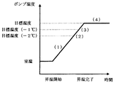
図5に昇温時間とポンプ温度の関係を、図6に目標温度との温度差とヒータ制御単位時間内のヒータ1の通電時間の関係を、図7に180Vと264V駆動時の経過時間とヒータ温度の関係を示す。
温度制御の制御単位時間として、ここでは2.5秒に設定され、昇温中はヒータ1の制御単位時間の間は、100%の通電としている。そして、図5に示すように、一旦、目標温度付近まで昇温すれば、後は温度を維持するために、目標温度との差に見合った時間だけヒータ1をオンにする。例えば、温度差が1℃であれば、図6に示すようにヒータ1の制御単位時間に対して50%の1.25秒間だけ通電し、図7に示す(3)での電流波形のように制御される。温度差が0.4℃であればヒータ制御単位時間に対して20%の0.5秒間だけ通電される。
【0004】
【発明が解決しようとする課題】
従来のターボ分子ポンプの温度制御回路は、以上のように構成されているが、ヒータ1の抵抗値は、一定時間(例えば1時間)でポンプが目標温度まで十分昇温するだけの電力を消費(発熱)するように設計されている。すなわち、電源装置の電源電圧仕様が180〜264Vとなっている場合、180Vで十分昇温するような抵抗値に設計される。
ところが、電源電圧180Vで昇温に十分な電流が流れる様に設計したヒータ1を、電源電圧264Vで使用すると、ヒータ1のオン時に流れる電流は264/180=1.47倍となり、ヒータで消費される電力で考えると(264/180)2=2.15倍となる。
そのまま使用すると、昇温時間はそれだけ短くなるが、昇温中の100%通電の状態では、ヒータは過昇温状態となり、寿命が短くなるという問題がある。
そこで、従来はトランスを用いてヒータヘの供給電圧が一定になるようにするか、または、電源電圧に合わせて複数の仕様のヒータを用意しなければならないという問題があった。
【0005】
本発明は、このような事情に鑑みてなされたものであって、異なる電源電圧の仕様に対しても、ポンプ本体に設けられたヒータの適正な昇温状態で加温することができるターボ分子ポンプの温度制御回路を提供することを目的とする。
【0006】
【課題を解決するための手段】
上記の目的を達成するため本発明のターボ分子ポンプの温度制御回路は、回転翼と固定翼とが交互に配置され低い圧力の条件下で高い回転速度で駆動され気体分子を排気するターボ分子ポンプに、反応生成物が内部に付着しないように電流を流して温度制御するヒータと、その温度検出手段と、目標温度と前記温度検出手段によるポンプ温度の差からヒータのオンオフ制御を行う回路を有するターボ分子ポンプの温度制御回路において、ヒータ電流の電流検出手段と、そのヒータの電流値の二乗の積算手段とを設けて、ヒータON中は前記電流値の二乗の積算手段からの積算値と、電流値の二乗のリミット値とを比較し、単位時間中にリミット値を越えた時は、単位時間の残り時間についてはヒータへの電力供給を停止するものである。
【0007】
本発明のターボ分子ポンプの温度制御回路は上記のように構成されており、ヒータ電流を検出する電流検出手段と、ヒータ通電中にヒータ電流を二乗(電力に比例)して積算するヒータ電流値の二乗の積算手段とを設けて、ヒータ制御手段が、目標温度との温度差により決定される通電時間の範囲内であっても、ヒータ電流の二乗の積算値が規定値(電流値の二乗のリミット値)を超えると、ヒータ制御単位時間内の残りの時間は、ヒータをオフにする機能を備えている。
そのため、単位時間あたりのヒータヘの供給電力が一定となるため、例えば電源電圧180V用に設計されたヒータを電源電圧264Vで使用しても、ヒータの過昇温を防止することができる。従って、1つのヒータで複数の電源電圧仕様に対応することができる。
【0008】
【発明の実施の形態】
本発明のターボ分子ポンプの温度制御回路の一実施例を図1を参照しながら説明する。図1に本発明のターボ分子ポンプの温度制御回路のブロック図を示す。本ターボ分子ポンプの温度制御回路は、反応生成物がポンプの内部に付着しないように温度制御するヒータ1と、内部温度を検出する温度検出計27を備えた温度検出手段2と、ヒータ1に流れる電流を検出する電流検出手段3と、ヒータ1の電流値の二乗の積算手段4と、目標温度8と温度検出手段2によるポンプ温度の差から、単位時間あたりのヒータ1のオン時間を計算する通電時間計算手段6と、通電時間計算手段6からの指示値、及び、ヒータ1の電流値の二乗の積算手段4からの積算値と電流値の二乗のリミット値7とを比較しその結果に基づいてスイッチング素子9のオンオフを行うヒータ制御手段5と、そのヒータ制御手段5によってヒータ1に流す電流をON、OFFするスイッチング素子9とから構成されている。
本ターボ分子ポンプの温度制御回路は、従来の温度制御回路にヒータ1に流れる電流を検出する電流検出手段3と、その電流値を二乗し積算する回路を有する電流値の二乗の積算手段4と、電流値の二乗のリミット値7とを増設したものである。それによって、ヒータ1に電流が流れている時、その電流値の二乗(電力に比例)の積算手段4からの積算値と、電流値の二乗(電力に比例)のリミット値7とを比較し、単位時間中に電流値の二乗(電力に比例)のリミット値7を越えた時は、ヒータ制御手段5からスイッチング素子9をOFFし、単位時間の残り時間についてヒータ1への電力供給を停止する。
【0009】
次に、電源電圧及び電力値の設計値が、180V、400Wであるヒータ1について、マイコンを用いたデジタル回路で説明する。180V、400Wのヒータ1の抵抗値は81Ωとなり、このヒータ1を180Vで使用した場合の電流値は2.22Aとなる。従って、このヒータ1は電流値が2.22Aであれば、連続通電しても寿命に問題のない設計であり、また、2.22A流さないと、ポンプを規定時間に昇温できないことになる。従って、電流値の二乗のリミット値7について、電源電圧180Vでヒータ制御単位時間中に100%ヒータ1をオンできるように設定する。ここで、ヒータ制御単位時間を2.5秒とし、電流値の二乗の計算を50ms毎に50回(=2.5s)行う場合、電流値の二乗のリミット値7は、2.22×2.22×50=246.4となる。
そして、電源電圧180Vでポンプの温度制御を行った場合を説明する。室温の状態から昇温を開始すると、通電時間計算手段6は、温度検出手段2からのポンプ温度と、目標温度8との温度差から、ヒータ制御手段5に対して、ヒータ制御単位時間の100%(=2.5s)の通電を指示する。そして、ヒータ制御手段5は、ヒータ1をオンすると共に、50ms毎に計算される、電流値の2乗の積算手段4の積算値を監視する。
図2(a)は、横軸に時間、縦軸にヒータ1の電流値の二乗の積算値を示し、(b)は縦軸にヒータ電流を示したものである。電源電圧が180Vの場合は、2.5s以内に電流値の2乗の積算値は、電流値の二乗のリミット値7(=246.4)には当然達しないので、(b)に示すように、100%通電(2.22A)のままポンプは昇温を続ける。この時、2.5s間にヒータが消費する電力は、2.22A×180V×2.5s=1000W・sとなる。
目標温度8との差が2℃以内になると、図6に示す直線に従って、通電時間計算手段6からの指示値は100%から順次減っていくので、ヒータ制御手段5はそれに従って、ヒータ制御単位時間(2.5s)のうち、オンにする時間を順次減らしていく。
次に、このヒータ1を電源電圧264Vで使用する場合を考える。180Vの場合と同様、室温の状態から昇温を開始すると、通電時間計算手段6は、ヒータ制御手段5に対して、ヒータ制御単位時間の100%(=2.5%)の通電を指示する。ヒータ制御手段5は、ヒータ1をオンすると共に、50ms毎に計算される、電流値の二乗の積算手段4の積算値を監視する。
電源電圧が264Vの場合は、ヒータオンの時に流れる電流は、264V/81Ω=3.26Aとなり、電流値の2乗の積算値は、246.4/(3.26×3.26)=23.2となって、24回目の1.2s後には、(a)に示すように、電流値の二乗のリミット値7(246.4)を越える。電流値の二乗の積算値が電流の二乗のリミット値7を越えると、ヒータ制御手段5は、通電時間計算手段6により指示された通電時間の範囲内であっても、(b)に示すように、ヒータ1に流れるヒータ電流をオフし、ヒータ1にそれ以上電力が供給されないようにする。
次のヒータ制御単位時間が開始されると、(b)に示すように、ヒータ制御手段5は再びヒータ1をオンにし、上記動作を繰り返す。この時、2.5s間にヒータ1が消費する電力は、3.26A×264V×1.2s=1033W・sとなり、電源電圧180Vで使用したときの1000W・sとほぼ同じになる。
目標温度8との差が2℃以内になると、図6の温度制御方法の通電時間の決定により、通電時間計算手段6からの指示値は、100%から順次減っていくが、指示されたオン時間が1.2s以上の場合は、電流値の二乗のリミット値7が効き、それ以上の時間ヒータ1をオンにはしない。通電時間計算手段6からの指示値が1.2s以下になるとヒータ制御手段5は、初めて通電時間計算手段6の指示通りの時間ヒータ1をオンするようになる。これにより、電源電圧264Vで使用した場合も、ヒータの過昇温を防止することができる。
【0010】
上記の実施例では、デジタル回路を利用した場合について説明しているが、アナログ回路による構成でも同様の機能は実施可能である。
【0011】
【発明の効果】
本発明のターボ分子ポンプの温度制御回路は上記のように構成されており、ポンプを加熱するヒータの電流を検出し、その検出されたヒータ電流を二乗(電力に比例)して積算する回路を設け、ポンプ内の温度検出値と目標温度との温度差により決定される通電時間の範囲内であっても、ヒータ電流の二乗の積算値が規定値(電流値の二乗のリミット値)を超えると、ヒータ制御単位時間内の残りの時間は、ヒータをオフにする機能を備えているので、単位時間あたりのヒータヘの供給電力が一定となり、ヒータの過昇温を防止することができる。
そのため、1種類のヒータを、ヒータの寿命を損なうことなく、複数の電源電圧に対応させることができる。そして、各種のヒータを準備する必要もなく、また、電圧変換用のトランスも必要でなくなる。
【図面の簡単な説明】
【図1】 本発明のターボ分子ポンプの温度制御回路の一実施例を示す図である。
【図2】 本発明のターボ分子ポンプの温度制御回路のヒータ制御電流の関係を示す図である。
【図3】 ターボ分子ポンプの断面構造を示す図である。
【図4】 従来のターボ分子ポンプの温度制御回路を示す図である。
【図5】 従来のターボ分子ポンプの昇温状態を示す図である。
【図6】 従来のターボ分子ポンプの温度制御の方法を示す図である。
【図7】 従来のターボ分子ポンプの各昇温時の通電状態を示す図である。
【符号の説明】
1…ヒータ
2…温度検出手段
3…電流検出手段
4…電流値の二乗の積算手段
5…ヒータ制御手段
6…通電時間計算手段
7…電流値の二乗のリミット値
8…目標温度
9…スイッチング素子[0001]
BACKGROUND OF THE INVENTION
The present invention relates to a turbo molecular pump, and more particularly to a temperature control circuit for a turbo molecular pump that prevents reaction products from adhering inside a turbo molecular pump used as an exhaust system in a semiconductor manufacturing apparatus or the like.
[0002]
[Prior art]
There is a turbo molecular pump as a vacuum pump for transporting gas by mechanically imparting momentum in a certain direction to gas molecules with a rotary blade or the like. The turbo molecular pump has the same shape as a rotor blade that has a slit cut diagonally in a disk under conditions of low pressure that allows collisions between gas molecules to be ignored, and the tilt of the slit is opposite to that of the rotor blade. The stationary blades are alternately arranged, and the rotor blades are driven at an extremely high rotational speed, allowing gas molecules to pass through the gap between the blades and being evacuated to obtain an ultra-high vacuum. It is. In the vacuum pumping system of the turbo molecular pump, an oil rotary pump, a dry vacuum pump or the like is used as a back pressure pump.
FIG. 3 shows a cross section of a turbo molecular pump equipped with a magnetic bearing device. In the turbo molecular pump, the
Since the
Therefore, a band heater 25 and a sheathed
[0003]
FIG. 4 shows a block diagram of a temperature control circuit in the power supply device. Depending on the film forming process, the reaction product may adhere to the inside of the pump, and the base portion of the pump is heated by the
The temperature control circuit includes a temperature detection means 2 having a temperature detector 27 provided inside the pump body, a
FIG. 5 shows the relationship between the temperature rise time and the pump temperature, FIG. 6 shows the relationship between the temperature difference from the target temperature and the energization time of the
Here, the control unit time of the temperature control is set to 2.5 seconds. During the temperature increase, the
[0004]
[Problems to be solved by the invention]
The temperature control circuit of the conventional turbo molecular pump is configured as described above, but the resistance value of the
However, if the
If it is used as it is, the temperature raising time will be shortened accordingly, but in the state of 100% energization during the temperature raising, there is a problem that the heater becomes overheated and the life is shortened.
Therefore, conventionally, there has been a problem that a transformer must be used to make the supply voltage constant, or a heater having a plurality of specifications must be prepared in accordance with the power supply voltage.
[0005]
The present invention has been made in view of such circumstances, and a turbo molecule that can be heated in an appropriate temperature rise state of a heater provided in a pump body even for specifications of different power supply voltages. An object of the present invention is to provide a temperature control circuit for a pump.
[0006]
[Means for Solving the Problems]
In order to achieve the above object, a temperature control circuit for a turbo molecular pump according to the present invention comprises a turbo molecular pump in which rotating blades and fixed blades are alternately arranged and driven at a high rotational speed under low pressure conditions to exhaust gas molecules. And a heater for controlling the temperature by supplying a current so that the reaction product does not adhere to the inside, a temperature detecting means for the heater, and a circuit for controlling the heater on / off from the difference between the target temperature and the pump temperature by the temperature detecting means. In the temperature control circuit of the turbo molecular pump, the heater current detection means and the heater current value square integration means are provided, and during the heater ON, the integration value from the current value square integration means, When the limit value of the square of the current value is compared and the limit value is exceeded during the unit time, the power supply to the heater is stopped for the remaining time of the unit time.
[0007]
The temperature control circuit of the turbo molecular pump of the present invention is configured as described above, and includes a current detection means for detecting the heater current, and a heater current value that integrates the heater current squared (proportional to power) while the heater is energized. Square heater, and the heater control means has a square value of the heater current square (the square of the current value) even if the heater control means is within the energization time range determined by the temperature difference from the target temperature. If the limit value) is exceeded, the remaining time within the heater control unit time has a function of turning off the heater.
For this reason, since the power supplied to the heater per unit time is constant, overheating of the heater can be prevented even when a heater designed for a power supply voltage of 180 V is used at a power supply voltage of 264 V, for example. Therefore, a single heater can cope with a plurality of power supply voltage specifications.
[0008]
DETAILED DESCRIPTION OF THE INVENTION
An embodiment of a temperature control circuit for a turbo molecular pump according to the present invention will be described with reference to FIG. FIG. 1 is a block diagram of a temperature control circuit of a turbo molecular pump according to the present invention. The temperature control circuit of the turbo molecular pump includes a
The turbo molecular pump temperature control circuit includes a current detection means 3 for detecting a current flowing in the
[0009]
Next, the
And the case where the temperature control of a pump is performed with the power supply voltage 180V is demonstrated. When the temperature rise is started from the room temperature state, the energization time calculation means 6 determines the heater control unit time of 100 with respect to the heater control means 5 from the temperature difference between the pump temperature from the temperature detection means 2 and the
FIG. 2A shows time on the horizontal axis, the integrated value of the square of the current value of the
When the difference from the
Next, consider the case where the
When the power supply voltage is 264 V, the current that flows when the heater is on is 264 V / 81Ω = 3.26 A, and the integrated value of the square of the current value is 246.4 / (3.26 × 3.26) = 23. 2, and after the 24th 1.2 s, as shown in (a), the limit value 7 (246.4) of the square of the current value is exceeded. When the integrated value of the square of the current value exceeds the
When the next heater control unit time is started, as shown in (b), the heater control means 5 turns on the
When the difference from the
[0010]
In the above-described embodiment, the case where a digital circuit is used has been described. However, a similar function can be implemented even with a configuration using an analog circuit.
[0011]
【The invention's effect】
The temperature control circuit of the turbo molecular pump of the present invention is configured as described above, and includes a circuit that detects the current of the heater that heats the pump and integrates the detected heater current by squaring (proportional to power). Even if it is within the range of the energization time determined by the temperature difference between the temperature detection value in the pump and the target temperature, the square value of the heater current exceeds the specified value (the limit value of the square of the current value). The remaining time within the heater control unit time has a function to turn off the heater, so that the power supplied to the heater per unit time is constant, and the heater can be prevented from being overheated.
Therefore, one type of heater can correspond to a plurality of power supply voltages without deteriorating the life of the heater. Further, it is not necessary to prepare various heaters and a voltage conversion transformer is not necessary.
[Brief description of the drawings]
FIG. 1 is a diagram showing an embodiment of a temperature control circuit of a turbo molecular pump according to the present invention.
FIG. 2 is a diagram showing a relationship of heater control currents in a temperature control circuit of a turbo molecular pump according to the present invention.
FIG. 3 is a view showing a cross-sectional structure of a turbo molecular pump.
FIG. 4 is a diagram showing a temperature control circuit of a conventional turbo molecular pump.
FIG. 5 is a diagram showing a temperature rise state of a conventional turbo molecular pump.
FIG. 6 is a diagram showing a temperature control method of a conventional turbo molecular pump.
FIG. 7 is a diagram showing a state of energization at each temperature increase of a conventional turbo molecular pump.
[Explanation of symbols]
DESCRIPTION OF
Claims (1)
Priority Applications (1)
| Application Number | Priority Date | Filing Date | Title |
|---|---|---|---|
| JP2000268861A JP3656532B2 (en) | 2000-09-05 | 2000-09-05 | Temperature control circuit of turbo molecular pump |
Applications Claiming Priority (1)
| Application Number | Priority Date | Filing Date | Title |
|---|---|---|---|
| JP2000268861A JP3656532B2 (en) | 2000-09-05 | 2000-09-05 | Temperature control circuit of turbo molecular pump |
Publications (2)
| Publication Number | Publication Date |
|---|---|
| JP2002070788A JP2002070788A (en) | 2002-03-08 |
| JP3656532B2 true JP3656532B2 (en) | 2005-06-08 |
Family
ID=18755571
Family Applications (1)
| Application Number | Title | Priority Date | Filing Date |
|---|---|---|---|
| JP2000268861A Expired - Lifetime JP3656532B2 (en) | 2000-09-05 | 2000-09-05 | Temperature control circuit of turbo molecular pump |
Country Status (1)
| Country | Link |
|---|---|
| JP (1) | JP3656532B2 (en) |
Families Citing this family (5)
| Publication number | Priority date | Publication date | Assignee | Title |
|---|---|---|---|---|
| JP4528019B2 (en) * | 2004-04-27 | 2010-08-18 | 株式会社大阪真空機器製作所 | Temperature control device for molecular pump |
| JP2006037739A (en) * | 2004-07-22 | 2006-02-09 | Koyo Seiko Co Ltd | Turbo-molecular pump device |
| JP6206002B2 (en) | 2013-08-30 | 2017-10-04 | 株式会社島津製作所 | Turbo molecular pump |
| JP6669010B2 (en) * | 2016-08-29 | 2020-03-18 | 株式会社島津製作所 | Vacuum pump |
| JP6942610B2 (en) * | 2017-07-14 | 2021-09-29 | エドワーズ株式会社 | A method for diagnosing a vacuum pump, a temperature control control device applied to the vacuum pump, an inspection jig, and a temperature control function unit. |
-
2000
- 2000-09-05 JP JP2000268861A patent/JP3656532B2/en not_active Expired - Lifetime
Also Published As
| Publication number | Publication date |
|---|---|
| JP2002070788A (en) | 2002-03-08 |
Similar Documents
| Publication | Publication Date | Title |
|---|---|---|
| CN111836968B (en) | Vacuum pump | |
| JP2527398B2 (en) | Turbo molecular pump | |
| KR20020040603A (en) | Vacuum pump | |
| US6679677B2 (en) | Vacuum pump | |
| US6832888B2 (en) | Molecular pump for forming a vacuum | |
| JP2003269367A (en) | Vacuum pump | |
| KR20030071525A (en) | Pump apparatus | |
| JP3656532B2 (en) | Temperature control circuit of turbo molecular pump | |
| JP2005083316A (en) | Motor control system and vacuum pump mounting the same | |
| US20030175131A1 (en) | Vacuum pump | |
| JP2015059464A (en) | Rotary vacuum pump | |
| JP3038432B2 (en) | Vacuum pump and vacuum device | |
| JP2002303293A (en) | Turbo-molecular pump | |
| CN108980073B (en) | Vacuum pump | |
| JP2597671Y2 (en) | Turbo molecular pump | |
| WO2022186076A1 (en) | Vacuum pump and vacuum exhaust device | |
| JP4882558B2 (en) | Turbo molecular pump | |
| JP2005083271A (en) | Vacuum pump | |
| JP3557608B2 (en) | Turbo molecular pump power supply | |
| JP2003148379A (en) | Turbo-molecular pump | |
| JPH074384A (en) | Compound molecular pump | |
| JPH11190294A (en) | Turbo molecular pump | |
| JP3456558B2 (en) | Turbo molecular pump | |
| JPH04164187A (en) | Turbo-molecular pump | |
| JP2003254284A (en) | Pump device |
Legal Events
| Date | Code | Title | Description |
|---|---|---|---|
| A977 | Report on retrieval |
Free format text: JAPANESE INTERMEDIATE CODE: A971007 Effective date: 20050209 |
|
| TRDD | Decision of grant or rejection written | ||
| A01 | Written decision to grant a patent or to grant a registration (utility model) |
Free format text: JAPANESE INTERMEDIATE CODE: A01 Effective date: 20050215 |
|
| A61 | First payment of annual fees (during grant procedure) |
Free format text: JAPANESE INTERMEDIATE CODE: A61 Effective date: 20050228 |
|
| R150 | Certificate of patent or registration of utility model |
Free format text: JAPANESE INTERMEDIATE CODE: R150 Ref document number: 3656532 Country of ref document: JP Free format text: JAPANESE INTERMEDIATE CODE: R150 |
|
| FPAY | Renewal fee payment (event date is renewal date of database) |
Free format text: PAYMENT UNTIL: 20080318 Year of fee payment: 3 |
|
| FPAY | Renewal fee payment (event date is renewal date of database) |
Free format text: PAYMENT UNTIL: 20090318 Year of fee payment: 4 |
|
| FPAY | Renewal fee payment (event date is renewal date of database) |
Free format text: PAYMENT UNTIL: 20100318 Year of fee payment: 5 |
|
| FPAY | Renewal fee payment (event date is renewal date of database) |
Free format text: PAYMENT UNTIL: 20100318 Year of fee payment: 5 |
|
| FPAY | Renewal fee payment (event date is renewal date of database) |
Free format text: PAYMENT UNTIL: 20110318 Year of fee payment: 6 |
|
| FPAY | Renewal fee payment (event date is renewal date of database) |
Free format text: PAYMENT UNTIL: 20110318 Year of fee payment: 6 |
|
| FPAY | Renewal fee payment (event date is renewal date of database) |
Free format text: PAYMENT UNTIL: 20120318 Year of fee payment: 7 |
|
| FPAY | Renewal fee payment (event date is renewal date of database) |
Free format text: PAYMENT UNTIL: 20120318 Year of fee payment: 7 |
|
| FPAY | Renewal fee payment (event date is renewal date of database) |
Free format text: PAYMENT UNTIL: 20130318 Year of fee payment: 8 |
|
| FPAY | Renewal fee payment (event date is renewal date of database) |
Free format text: PAYMENT UNTIL: 20140318 Year of fee payment: 9 |
|
| EXPY | Cancellation because of completion of term |