JP3655938B2 - Fuel injection device for internal combustion engine - Google Patents
Fuel injection device for internal combustion engine Download PDFInfo
- Publication number
- JP3655938B2 JP3655938B2 JP30395094A JP30395094A JP3655938B2 JP 3655938 B2 JP3655938 B2 JP 3655938B2 JP 30395094 A JP30395094 A JP 30395094A JP 30395094 A JP30395094 A JP 30395094A JP 3655938 B2 JP3655938 B2 JP 3655938B2
- Authority
- JP
- Japan
- Prior art keywords
- pressure
- valve
- chamber
- injection
- fuel
- Prior art date
- Legal status (The legal status is an assumption and is not a legal conclusion. Google has not performed a legal analysis and makes no representation as to the accuracy of the status listed.)
- Expired - Fee Related
Links
Images

Classifications
-
- F—MECHANICAL ENGINEERING; LIGHTING; HEATING; WEAPONS; BLASTING
- F02—COMBUSTION ENGINES; HOT-GAS OR COMBUSTION-PRODUCT ENGINE PLANTS
- F02M—SUPPLYING COMBUSTION ENGINES IN GENERAL WITH COMBUSTIBLE MIXTURES OR CONSTITUENTS THEREOF
- F02M63/00—Other fuel-injection apparatus having pertinent characteristics not provided for in groups F02M39/00 - F02M57/00 or F02M67/00; Details, component parts, or accessories of fuel-injection apparatus, not provided for in, or of interest apart from, the apparatus of groups F02M39/00 - F02M61/00 or F02M67/00; Combination of fuel pump with other devices, e.g. lubricating oil pump
- F02M63/0003—Fuel-injection apparatus having a cyclically-operated valve for connecting a pressure source, e.g. constant pressure pump or accumulator, to an injection valve held closed mechanically, e.g. by springs, and automatically opened by fuel pressure
- F02M63/0007—Fuel-injection apparatus having a cyclically-operated valve for connecting a pressure source, e.g. constant pressure pump or accumulator, to an injection valve held closed mechanically, e.g. by springs, and automatically opened by fuel pressure using electrically actuated valves
-
- F—MECHANICAL ENGINEERING; LIGHTING; HEATING; WEAPONS; BLASTING
- F02—COMBUSTION ENGINES; HOT-GAS OR COMBUSTION-PRODUCT ENGINE PLANTS
- F02B—INTERNAL-COMBUSTION PISTON ENGINES; COMBUSTION ENGINES IN GENERAL
- F02B3/00—Engines characterised by air compression and subsequent fuel addition
- F02B3/06—Engines characterised by air compression and subsequent fuel addition with compression ignition
Description
【0001】
【産業上の利用分野】
本発明は、内燃機関用の燃料噴射装置であって、燃料を低圧室から高圧集合室に圧送する燃料高圧ポンプが設けられており、高圧集合室が高圧導管と圧力導管とを介して、燃料供給される内燃機関の燃焼室に突入している噴射弁と接続されており、該噴射弁の開閉運動がそれぞれ、各噴射弁において高圧導管と圧力導管との間に配置されている電気制御式の制御弁によって制御されるようになっており、高圧導管において高圧集合室と噴射弁との間に組み込まれている別の圧力蓄え室が、各噴射弁に設けられている形式のものに関する。
【0002】
【従来の技術】
ドイツ連邦共和国特許出願公開第3700687号明細書に基づいて公知のこのような形式の燃料噴射装置では、燃料高圧ポンプが燃料を低圧室から高圧集合室に圧送し、この高圧集合室は高圧導管を介して、燃料供給される内燃機関の燃焼室に突入している個々の噴射弁と接続されており、この場合この共通の圧力蓄え系(Druckspeichersystem)は1つの圧力制御装置によって規定の圧力に保たれる。噴射弁における噴射時間及び噴射量の制御のために、噴射弁にはそれぞれ、電気制御式の制御弁が高圧導管に挿入されており、この制御弁はその開閉によって、噴射弁における燃料高圧噴射を制御するようになっている。
【0003】
この場合公知の燃料噴射装置では各噴射弁に1つずつ別の圧力蓄え室(Druckspeicherraum)が設けられており、該圧力蓄え室は共通の圧力蓄え系から燃料を満たされ、かつ、高圧集合室から延びる高圧導管の他に同様に噴射弁と接続されている。このように各噴射弁における蓄え容積を、規定の長さの導管によって接続されている2つの圧力室に分割することによって、噴射弁の弁部材に作用する圧力室から燃料が絞られて流出することに関連して、噴射経過を、各内燃機関の必要性に最低に合わせることが可能であり、この場合特に噴射開始におけるゆっくりとした圧力上昇と噴射終了時における高い圧力上昇が達成可能である。共通の高圧集合室から直接噴射弁に供給される燃料量は、この場合単に、噴射弁の弁部材の行程運動を制御するための制御手段として使用され、これに対して噴射量は完全に、それぞれ所属の小さな圧力蓄え室から取り出される。
【0004】
しかしながらこの場合公知の燃料噴射装置には次のような欠点がある。すなわち公知の燃料噴射装置では圧力蓄え室と噴射弁部材における圧力室との間のハイドロリック的な接続によって、高い系圧が常に噴射弁部材において作用しており、この結果噴射弁に高い機械的な負荷が加えられることになる。
【0005】
さらに公知の燃料噴射装置では噴射動作が、圧力蓄え室における燃料によって噴射弁の弁部材における圧力室のハイドロリック的なロック又は放圧を用いて制御されることに基づいて、系における圧力変動が生ぜしめられる。そしてこれによって、高圧導管を介して接続されている個々の噴射弁における制御動作が相互に影響を受けることがあり、ひいては不正確さを生ぜしめることになる。さらにまた、噴射弁及び該噴射弁と接続された圧力接続部毎に2つの高圧導管が配置されていることによって、製作費が高騰し、この結果公知の燃料噴射装置は、構成的に簡単な構造、長い運転時間にわたる噴射精度及び高い運転確実性に関するその都度の高い要求に相応することができない。
【0006】
【発明が解決しようとする課題】
ゆえに本発明の課題は、冒頭に述べた形式の燃料噴射装置を改良して、高い系圧が常に噴射弁のところに存在することを回避することができる燃料噴射装置を提供することである。
【0007】
【課題を解決するための手段】
この課題を解決するために本発明の構成では、噴射弁に設けられた制御弁が、リングウェブを備えたピストン状の弁部材を有しており、該リングウェブの、直径を減じられた弁部材シャフトへの移行面が、円錐形に構成されていて、かつ円錐形の弁座と共働する第1の弁シール面を形成しており、さらにリングウェブの、直径を減じられた弁部材シャフトへの別の移行が、リング段部を介して行われており、該リング段部の、リングウェブとは反対側の軸方向のリング端面が、第2の平らな弁シール面を形成していて、該第2の弁シール面が、ケーシング固定の平らな弁座と共働するようになっており、噴射弁の噴射休止中に制御弁が第1の弁シール面と円錐形の弁座との接触によって、圧力蓄え室と、噴射弁の内部に配置されていて該噴射弁の弁部材を開放方向において負荷する圧力室との間の接続部を閉鎖し、かつ制御弁の第2の弁シール面とケーシング固定の平らな弁座との接触によって、噴射弁の圧力室と放圧室との間の接続部を閉鎖制御するようになっている。
【0008】
【発明の効果】
本発明のように構成された燃料噴射装置には公知のものに比べて次のような利点がある。すなわち本発明による燃料噴射装置では、噴射弁が制御弁によって噴射休止中に圧力系から隔てられるので、高い系圧が常に噴射弁において作用することはなくなる。このことによって、噴射弁に対する機械的な負荷が小さくなるのみならず、噴射弁の弁部材がその弁ばねによって閉鎖されて、閉鎖状態に保持されることが可能になり、このことは、閉鎖方向における弁部材の高い圧力負荷を不要にし、ひいては噴射装置全体の簡単化に役立つ。このことは、ダブル座弁として構成された電気式の制御弁によって有利にかつ簡単に達成される。そしてこの場合制御弁の各行程ストッパは、弁座によって形成されており、両行程方向における弁部材のそれぞれ等しい大きさに寸法設定された圧力作用面が、開放状態においても閉鎖状態においても圧力バランスされるので、この結果、弁部材を操作する電磁弁の調節力は、単に戻しばねの力を克服するだけでよい。
【0009】
本発明による燃料噴射装置の別の利点は、制御弁のピストン状の弁部材に貫通孔が設けられていることによって得られる。すなわちこの場合この貫通孔を介して、高圧下にある燃料が噴射休止中に、制御弁内の高圧範囲から放圧室に流出し、そして該貫通孔を介して、弁部材の両端面における圧力バランス、つまり該両端面に隣接する室の圧力バランスが常に行われる。
【0010】
噴射開始時に圧力上昇が小さくかつ噴射終了に向かって高い噴射圧を有するような噴射圧経過を達成するために、噴射弁に配属された圧力蓄え室の容積は、噴射弁における最大噴射量よりも5〜20倍大きく構成されており、この場合噴射開始時に噴射弁において反射された燃料圧は、圧力蓄え室において、系圧を上回る値への圧力上昇のために利用される。この圧力上昇はこの場合、高圧導管の寸法設定と供給路における圧力弁とによって調節可能な、圧力蓄え室への後流(Nachstroemen)を介して、次のように、すなわち噴射終了の範囲において最高の燃料圧が形成されるように合わせられることができる。そして圧力蓄え室の圧力接続部に挿入された絞りによって、圧力変動が系に伝わることが回避される。
【0011】
【実施例】
次に図面につき本発明の実施例を説明する。
【0012】
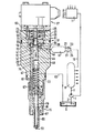
図1に示された燃料噴射装置において燃料高圧ポンプ1は、吸込み側で燃料供給導管3を介して燃料を満たされた低圧室5と接続され、かつ圧力側で吐出導管7を介して高圧集合室9と接続されており、この場合燃料高圧ポンプ1の吐出量は電気式の制御装置11によって制御可能である。
【0013】
高圧集合室9からは高圧導管13が、燃料供給される内燃機関の燃焼室に突入している個々の噴射弁15に通じており、この場合噴射動作を制御するために、各1つの電気式の制御弁17が、各噴射弁15においてそれぞれの高圧導管13に挿入されている。さらに各高圧導管13には高圧集合室9と制御弁17との間に別の圧力蓄え室19が設けられており、この圧力蓄え室19の容積は、噴射動作毎の噴射弁15における最大噴射量のほぼ5〜20倍の大きさである。圧力蓄え室19は並列な2つの圧力接続部を介して、高圧集合室9に通じる高圧導管13の部分と接続されている。この場合第1の圧力接続部21は、圧力蓄え室19に向かって開放する逆止弁として構成された圧力弁23を有しており、かつ第2の圧力接続部25は絞り27を有している。この場合一方では絞り27を介して、高圧集合室9に通じる高圧導管13の部分への燃料のコントロールされない逆流を回避すること、及び残りの噴射弁の圧力蓄え室における圧力に対する影響を回避することが望まれており、かつ他方では圧力弁23が圧力蓄え室19への迅速な燃料補充を可能にしている。この場合、高圧導管13の寸法設定に依存して絞り27と圧力弁23とを設計することによって、圧力蓄え室19への流入・流出量、特に高圧噴射中における圧力蓄え室19への流入・流出量を調節することが可能であり、しかもこの場合絞り27と圧力弁23とは、共通の圧力接続部において直列接続されて配置されていてもよい。
【0014】
制御弁17は3ポート2位置方向制御弁として構成されており、この制御弁17のピストン状の弁部材29は、ケーシング31とばね受33との間において弁部材29に支持されている圧縮ばね35に抗して端面に作用する電気式の調節磁石37によって操作され、この調節磁石37への給電は制御装置11によって制御される。この場合弁部材29はそのシャフトにリングウェブ39を有しており、このリングウェブ39の、調節磁石37とは反対側の下側の移行面は、ピストンシャフトに向かって円錐形に構成されていて、この場合弁部材29において第1の円錐形の弁シール面41を形成しており、この弁シール面41は円錐形の弁座43と協働する。図2において拡大されて示されているこの円錐形の弁座43は、この場合、弁部材29におけるガイドピストン部分45を収容するガイド孔49の円錐形の直径拡大部によって、制御弁17のケーシング31の内側に設けられている。この場合、弁部材29を調節磁石とは反対の側で制限しているガイドピストン部分45と、円錐形の弁シール面41との間には、弁部材29にリング溝47が設けられており、このリング溝47はガイド孔49の壁と一緒に圧力室51を形成している。この圧力室51は、リングウェブ39における円錐形の弁シール面41とガイドピストン部分45とによって制限され、かつ、圧力蓄え室19から導出していて制御弁17に通じる高圧導管13の部分に開口しており、この場合この開口は、弁部材29の行程運動中に弁部材29によって閉鎖され得ないようになっている。
【0015】
リングウェブ39からピストンシャフトへの調節磁石37側の移行は、リング段部53を介して行われており、この場合リング段部53における軸方向に向けられたリング面は、第2の平らな弁シール面55を形成しており、この弁シール面55は、中間部材61の軸方向の端面に設けられていて孔57を取り囲む扁平弁座59と協働する。この場合ピストンシャフトは孔57を貫いて調節磁石37に向かってさらに延びていて、その端部で、弁部材29の圧縮ばね35を収容するばね室63の中に突入している。平らな軸方向の弁シール面55を有する、リングウェブ39におけるリング段部53の直径は、この場合開放された制御弁17における圧力バランスのために、ガイドピストン部分45の直径よりも大きい。
【0016】
弁部材29の行程運動はこの場合その都度、一方の弁座43,59における弁シール面41,55の当接によって制限される。リングウェブ39は、各弁座43,59によって制限されていて前室65を形成しているリング室内に配置されており、このリング室からは圧力導管67が噴射弁15に通じ、かつ放圧導管69が延びている。この放圧導管69はこの場合部分的に、ピストンシャフトと中間部材61に設けられた孔57との間に残っているリング間隙によって形成されている。このリング間隙はその外径を弁シール面55よりも小さく構成されており、したがってこの弁シール面55によって閉鎖可能である。孔57はこの場合弁部材29の、戻しばねとして作用する圧縮ばね35を収容するばね室63に開口しており、かつ弁部材29における軸方向の貫通孔71と交差する横孔73を介して、弁部材29のガイドピストン45の、調節磁石37とは反対側の端面によって制限された放圧室75と接続されている。ガイド孔49によって形成されているこの放圧室75は、軸方向で見て調節磁石37から離れる方向で、噴射弁15のばね室77に続いている。このばね室77には、噴射弁15の弁部材79を閉鎖方向で負荷する弁ばね81が配置されており、かつこのばね室77からは、戻し導管83が低圧室5に通じている。
【0017】
この場合噴射弁15の弁部材79には公知の形式で円錐形の圧力肩部85が設けられており、この圧力肩部85は、圧力導管67と接続された圧力室87に突入していて、該圧力室87における圧力が弁部材79を開放方向に負荷するようになっている。圧力室87からはさらに噴射通路89が弁部材79に沿って、弁部材79の先端におけるシール面によって制御される噴射弁15の単数又は複数の噴射開口91に通じており、このもしくはこれらの噴射開口91は、燃料供給される内燃機関の図示されていない燃焼室に突入している。
【0018】
本発明による燃料噴射装置は以下のように作動する。
【0019】
燃料高圧ポンプ1は燃料を低圧室5から高圧集合室9に圧送して、この高圧集合室9において燃料高圧を形成し、この燃料高圧は燃料高圧ポンプ1の制御を介して調節可能である。この燃料高圧は高圧導管13を介して、噴射弁15における個々の制御弁17の圧力室51に至るまで続き、この場合圧力弁23を介してそれぞれの圧力蓄え室19をも満たす。休止状態、つまり噴射弁15が閉鎖されている場合に、制御弁17における調節磁石37は無電流に切り換えられており、この結果圧縮ばね35は弁部材29をばね受33を介して円錐形の弁シール面41で、円錐形の弁座43との接触状態に保ち、これによって、燃料高圧下にある圧力室51と、噴射弁15に通じている圧力導管67と常に接続されている前室65との間における接続部が閉鎖されて、前室65から放圧通路69への接続部が開放されることになる。
【0020】
噴射弁15において噴射を行うことが望まれている場合には、調節磁石37が給電され、この調節磁石37は制御弁17をばね35の戻し力に抗して、その平らな弁シール面55が弁座59に接触するまでシフトさせる。この場合に放圧通路69に通じる前室65の接続部が閉鎖され、圧力導管67に通じる前室65の接続部が開放制御され、この結果燃料高圧はいまや圧力室51から前室65と圧力導管67とを介して噴射弁15の圧力室87に導かれ、そしてこの圧力室87において弁部材79がその弁座から持ち上げられることによって、噴射開口91において噴射が行われる。
【0021】
この場合噴射段階中に圧力導管67においては、系圧を介して圧力過剰上昇が以下のようにして生じることがある。すなわち弁部材29のシフトによって圧力室51は前室65と接続され、これによって横孔73及び貫通孔71の方向における流れが、無圧の戻し導管83にまで導入される。この流れに起因してさらに、圧力蓄え室19から圧力室51への導管接続部における流れと、圧力蓄え室19と高圧集合室9との間の導管13における流れとが生じる。
【0022】
弁座59における弁シール面55の接触によって弁部材29の開放行程が終了すると、燃料流は圧力導管67の方向に導かれる。運動している燃料流のせき止め効果によって、そこで圧力過剰上昇が発生する。この圧力過剰上昇は、流入値、導管長さ、導管直径、圧力蓄え室容積、絞り横断面等を適宜に選択することによって影響可能である。
【0023】
さらに、流れエネルギの転換によって、系圧の値を越えた噴射圧の圧力上昇を達成することが可能である。この場合、噴射弁15に通じる燃料圧力波が部分的に噴射弁において反射され、圧力蓄え室19へと戻され、そしてこの圧力蓄え室19において圧力上昇を生ぜしめる。この圧力上昇は、高圧集合室9から後流れする燃料の流れエネルギと、迅速な圧力消滅を阻止する絞り27の寸法設定とによって、調節されることができる。この高められた燃料圧は、次いで新たに噴射弁15に達し、噴射終了範囲における噴射弁15の噴射率を高める。噴射弁15における噴射経過は、さらに、弁部材29における開口横断面積(直径/行程)、前室65及び圧力導管67における容積、並びに圧力蓄え室19の容積を介して、形成することが可能である。
【0024】
噴射を終了させたい場合には、調節磁石37が新たに無電流に切り換えられ、圧縮ばね35が、開放状態においてもリング段部53によって圧力バランスされている制御弁17の弁部材29を、再び、円錐形の弁座43との接触状態にもたらす。この場合に扁平弁座59における開放横断面が開放制御され、これによって高圧下にある燃料は、放圧通路69とばね室63と弁部材29における横孔73及び縦孔71とを介して、放圧室75に放圧される。この放圧室75から燃料はさらにばね室77と戻し導管83とを介して低圧室5に流出し、この結果噴射弁15の弁部材79は圧力負荷を軽減され弁ばね81の作用下で閉鎖位置へと移動し、弁部材29は再び圧力バランスされる。この場合放圧通路69の横断面は次のように、すなわち放圧通路69が一方では圧力導管67における迅速な圧力消滅を噴射弁15の閉鎖圧下で保証するように設計されており、しかしながら他方では圧力導管67からの流出が絞られて、噴射休止中に圧力導管67及び噴射弁15において残留圧が残るように設計されている。
【0025】
噴射終了時に閉鎖された制御弁17から戻る圧力波によって加えられる個々の噴射弁15に対する影響を回避するために、圧力蓄え室19の容積と、戻し導管として働く圧力接続部25における絞り27の横断面積とは次のように、すなわち圧力蓄え室19における圧力ピークと高圧集合室9への圧力ピークとが消滅させられるように、合わせられている。
【図面の簡単な説明】
【図1】本発明による燃料噴射装置を示す縦断面図である。
【図2】図1に示された制御弁のシール面及び弁座の構成を拡大して示す図である。
【符号の説明】
1 燃料高圧ポンプ、 3 燃料供給導管、 5 低圧室、 7 吐出導管、9 高圧集合室、 11 制御装置、 13 高圧導管、 15 噴射弁、 17 制御弁、 19 圧力蓄え室、 21,25 圧力接続部、 23 圧力弁、 27 絞り、 29 弁部材、 31 ケーシング、 33 ばね受、 35 圧縮ばね、 37 調節磁石、 39 リングウェブ、 41 弁シール面、 43 弁座、 45 ガイドピストン部分、 47 リング溝、 49 ガイド孔、 51 圧力室、 53 段部、 55 弁シール面、 57 孔、59 弁座、 61 中間部材、 63 ばね室、 65 前室、 67 圧力導管、 69 放圧導管、 71 貫通孔、 73 横孔、 75 放圧室、77 ばね室、 79 弁部材、 81 弁ばね、 83 戻し導管、 85圧力肩部、 87 圧力室、 89 噴射通路、 91 噴射開口[0001]
[Industrial application fields]
The present invention is a fuel injection device for an internal combustion engine, and is provided with a fuel high-pressure pump that pumps fuel from a low-pressure chamber to a high-pressure collecting chamber. The high-pressure collecting chamber is connected to the fuel via a high-pressure conduit and a pressure conduit. Electrically controlled, connected to an injection valve entering the combustion chamber of the internal combustion engine to be supplied, the opening and closing movement of the injection valve being respectively arranged between the high-pressure conduit and the pressure conduit in each injection valve The control valve is controlled by a control valve, and a separate pressure storage chamber is provided in the high-pressure conduit between the high-pressure collecting chamber and the injection valve.
[0002]
[Prior art]
In this type of fuel injection device known from DE 3700687 A1, a high-pressure fuel pump pumps fuel from a low-pressure chamber into a high-pressure collection chamber, which is connected to a high-pressure conduit. In this case, this common pressure storage system (Druckspeichersystem) is maintained at a specified pressure by a single pressure control device. Be drunk. In order to control the injection time and the injection amount in the injection valve, an electric control valve is inserted in the high-pressure conduit in each injection valve, and this control valve opens and closes the fuel high-pressure injection in the injection valve. It comes to control.
[0003]
In this case, in the known fuel injection device, a separate pressure storage chamber (Druckspeicherraum) is provided for each injection valve, the pressure storage chamber being filled with fuel from a common pressure storage system, and a high pressure collection chamber In addition to a high-pressure conduit extending from the same, it is also connected to an injection valve. In this way, by dividing the storage volume in each injection valve into two pressure chambers connected by a conduit having a predetermined length, the fuel is throttled out of the pressure chamber acting on the valve member of the injection valve. In connection with this, it is possible to minimize the course of the injection to the needs of each internal combustion engine, in which case a slow pressure increase at the start of the injection and a high pressure increase at the end of the injection can be achieved. . The amount of fuel supplied directly from the common high-pressure collection chamber to the injection valve is in this case simply used as a control means for controlling the stroke movement of the valve member of the injection valve, whereas the injection amount is completely Each is taken out of the small pressure storage room of the belonging.
[0004]
However, in this case, the known fuel injection device has the following drawbacks. That is, in the known fuel injection device, a high system pressure always acts on the injection valve member due to a hydraulic connection between the pressure storage chamber and the pressure chamber of the injection valve member. As a result, a high mechanical pressure is applied to the injection valve. Load will be added.
[0005]
Further, in the known fuel injection device, the pressure fluctuation in the system is caused based on the fact that the injection operation is controlled by the fuel in the pressure storage chamber using the hydraulic lock or release of the pressure chamber in the valve member of the injection valve. Be born. This in turn can affect the control action of the individual injection valves connected via the high-pressure conduit, which can lead to inaccuracies. Furthermore, the arrangement of two high-pressure conduits for each injection valve and each pressure connection connected to the injection valve increases the production costs. As a result, the known fuel injection device has a simple construction. The high demands on design, injection accuracy over long operating times and high operational certainty cannot be met.
[0006]
[Problems to be solved by the invention]
Therefore, an object of the present invention is to provide a fuel injection device capable of improving the fuel injection device of the type described at the beginning and avoiding that a high system pressure always exists at the injection valve.
[0007]
[Means for Solving the Problems]
In order to solve this problem, in the configuration of the present invention, the control valve provided in the injection valve has a piston-like valve member provided with a ring web, and the diameter of the ring web is reduced. The reduced diameter valve member of the ring web, the transition surface to the member shaft being conically configured and forming a first valve seal surface cooperating with the conical valve seat Another transition to the shaft takes place via the ring step, the axial ring end surface of the ring step opposite the ring web forming a second flat valve sealing surface. The second valve seal surface cooperates with a flat valve seat fixed to the casing, and the control valve is connected to the first valve seal surface and the conical valve during the injection pause of the injection valve. The pressure storage chamber and the injection valve are arranged inside the injection valve by contact with the seat. And the pressure chamber of the injection valve by contact between the second valve sealing surface of the control valve and the flat valve seat fixed to the casing. The connection between the pressure release chamber is controlled to be closed .
[0008]
【The invention's effect】
The fuel injection device configured as in the present invention has the following advantages over known devices. That is, in the fuel injection device according to the present invention, since the injection valve is separated from the pressure system by the control valve during the injection suspension, a high system pressure does not always act on the injection valve. This not only reduces the mechanical load on the injection valve, but also allows the valve member of the injection valve to be closed by its valve spring and held in a closed state, This eliminates the need for a high pressure load on the valve member and thus simplifies the entire injection device. This is achieved advantageously and simply by means of an electric control valve configured as a double seat valve. In this case, each stroke stopper of the control valve is formed by a valve seat, and the pressure acting surface dimensioned to the same size of the valve member in both stroke directions has a pressure balance in both the open state and the closed state. Thus, as a result, the adjusting force of the solenoid valve that operates the valve member need only overcome the force of the return spring.
[0009]
Another advantage of the fuel injection device according to the present invention is obtained by providing a through hole in the piston-like valve member of the control valve. That is, in this case, the fuel under high pressure flows out from the high pressure range in the control valve to the pressure release chamber through the through hole, and the pressures at the both end faces of the valve member through the through hole. The balance, that is, the pressure balance between the chambers adjacent to both end faces is always performed.
[0010]
The volume of the pressure storage chamber assigned to the injection valve is larger than the maximum injection amount in the injection valve in order to achieve an injection pressure course in which the pressure rise is small at the start of injection and has a high injection pressure toward the end of injection. In this case, the fuel pressure reflected by the injection valve at the start of injection is used for increasing the pressure to a value exceeding the system pressure in the pressure storage chamber. This pressure rise is in this case maximum via the wake (Nachstroemen), which is adjustable by the dimensioning of the high-pressure line and the pressure valve in the supply line, as follows: The fuel pressure can be adjusted to be formed. And it is avoided that a pressure fluctuation is transmitted to a system | strain by the throttle inserted in the pressure connection part of a pressure storage chamber.
[0011]
【Example】
Next, embodiments of the present invention will be described with reference to the drawings.
[0012]
In the fuel injection device shown in FIG. 1, a high-pressure fuel pump 1 is connected to a low-
[0013]
From the high-pressure collection chamber 9, high-
[0014]
The
[0015]
The transition from the
[0016]
In this case, the stroke movement of the
[0017]
In this case, the
[0018]
The fuel injection device according to the present invention operates as follows.
[0019]
The fuel high pressure pump 1 pumps fuel from the
[0020]
When it is desired to perform injection at the
[0021]
In this case, an excessive pressure increase may occur in the
[0022]
When the opening stroke of the
[0023]
Furthermore, by increasing the flow energy, it is possible to achieve an increase in injection pressure that exceeds the system pressure value. In this case, the fuel pressure wave leading to the
[0024]
When it is desired to end the injection, the adjusting
[0025]
In order to avoid the influence on the
[Brief description of the drawings]
FIG. 1 is a longitudinal sectional view showing a fuel injection device according to the present invention.
FIG. 2 is an enlarged view showing a configuration of a seal surface and a valve seat of the control valve shown in FIG.
[Explanation of symbols]
DESCRIPTION OF SYMBOLS 1 Fuel high pressure pump, 3 Fuel supply conduit, 5 Low pressure chamber, 7 Discharge conduit, 9 High pressure collecting chamber, 11 Control apparatus, 13 High pressure conduit, 15 Injection valve, 17 Control valve, 19 Pressure storage chamber, 21, 25 Pressure connection part , 23 Pressure valve, 27 Throttle, 29 Valve member, 31 Casing, 33 Spring support, 35 Compression spring, 37 Adjustment magnet, 39 Ring web, 41 Valve seal surface, 43 Valve seat, 45 Guide piston part, 47 Ring groove, 49 Guide hole, 51 pressure chamber, 53 step portion, 55 valve sealing surface, 57 hole, 59 valve seat, 61 intermediate member, 63 spring chamber, 65 front chamber, 67 pressure conduit, 69 pressure relief conduit, 71 through-hole, 73 lateral Hole, 75 pressure release chamber, 77 spring chamber, 79 valve member, 81 valve spring, 83 return conduit, 85 pressure shoulder, 87 pressure chamber, 89 injection passage, 91 injection opening
Claims (12)
噴射弁(15)に設けられた制御弁(17)が、リングウェブ(39)を備えたピストン状の弁部材(29)を有しており、該リングウェブ(39)の、直径を減じられた弁部材シャフトへの移行面が、円錐形に構成されていて、かつ円錐形の弁座(43)と共働する第1の弁シール面(41)を形成しており、さらにリングウェブ(39)の、直径を減じられた弁部材シャフトへの別の移行が、リング段部(53)を介して行われており、該リング段部(53)の、リングウェブ(39)とは反対側の軸方向のリング端面が、第2の平らな弁シール面(55)を形成していて、該第2の弁シール面(55)が、ケーシング固定の平らな弁座(59)と共働するようになっており、
噴射弁(15)の噴射休止中に制御弁(17)が第1の弁シール面(41)と円錐形の弁座(43)との接触によって、圧力蓄え室(19)と、噴射弁(15)の内部に配置されていて該噴射弁(15)の弁部材(79)を開放方向において負荷する圧力室(87)との間の接続部を閉鎖し、かつ制御弁(17)の第2の弁シール面(55)とケーシング固定の平らな弁座(59)との接触によって、噴射弁(15)の圧力室(87)と放圧室(75)との間の接続部を閉鎖制御するようになっていることを特徴とする、内燃機関用の燃料噴射装置。A fuel injection device for an internal combustion engine is provided with a fuel high-pressure pump (1) for pumping fuel from a low-pressure chamber (5) to a high-pressure collecting chamber (9), and the high-pressure collecting chamber (9) is connected to a high-pressure conduit ( 13) and a pressure conduit (67) are connected to an injection valve (15) that has entered the combustion chamber of the internal combustion engine to be supplied with fuel, and the opening and closing movements of the injection valve (15) are respectively Each injection valve (15) is controlled by an electrically controlled control valve (17) disposed between the high pressure conduit (13) and the pressure conduit (67), and the high pressure conduit (13) In the type in which another pressure storage chamber (19) incorporated between the high pressure collecting chamber (9) and the injection valve (15) is provided in each injection valve (15),
A control valve (17) provided on the injection valve (15) has a piston-like valve member (29) with a ring web (39), and the diameter of the ring web (39) is reduced. The transition surface to the valve member shaft is conical and forms a first valve sealing surface (41) cooperating with the conical valve seat (43), 39) another transition to the reduced diameter valve member shaft is made via the ring step (53), which is opposite to the ring web (39). The axial ring end face on the side forms a second flat valve seal surface (55) which is co-located with the flat valve seat (59) fixed on the casing. Have come to work,
The control valve (17) contacts the first valve seal surface (41) and the conical valve seat (43) during the injection stop of the injection valve (15), so that the pressure storage chamber (19) and the injection valve ( 15), which closes the connection between the pressure chamber (87) which is arranged inside the injection valve (15) and loads the valve member (79) of the injection valve (15) in the opening direction, and the control valve (17) The connection between the pressure chamber (87) and the pressure relief chamber (75) of the injection valve (15) is closed by contact between the valve seal surface (55) of the two and the flat valve seat (59) fixed to the casing. A fuel injection device for an internal combustion engine, characterized by being controlled .
Applications Claiming Priority (2)
| Application Number | Priority Date | Filing Date | Title |
|---|---|---|---|
| DE4341543A DE4341543A1 (en) | 1993-12-07 | 1993-12-07 | Fuel injection device for internal combustion engines |
| DE4341543.1 | 1993-12-07 |
Publications (2)
| Publication Number | Publication Date |
|---|---|
| JPH07189849A JPH07189849A (en) | 1995-07-28 |
| JP3655938B2 true JP3655938B2 (en) | 2005-06-02 |
Family
ID=6504295
Family Applications (1)
| Application Number | Title | Priority Date | Filing Date |
|---|---|---|---|
| JP30395094A Expired - Fee Related JP3655938B2 (en) | 1993-12-07 | 1994-12-07 | Fuel injection device for internal combustion engine |
Country Status (4)
| Country | Link |
|---|---|
| US (1) | US5497750A (en) |
| EP (1) | EP0657642B1 (en) |
| JP (1) | JP3655938B2 (en) |
| DE (2) | DE4341543A1 (en) |
Families Citing this family (45)
| Publication number | Priority date | Publication date | Assignee | Title |
|---|---|---|---|---|
| US5687693A (en) | 1994-07-29 | 1997-11-18 | Caterpillar Inc. | Hydraulically-actuated fuel injector with direct control needle valve |
| US5669355A (en) * | 1994-07-29 | 1997-09-23 | Caterpillar Inc. | Hydraulically-actuated fuel injector with direct control needle valve |
| US5526791A (en) * | 1995-06-07 | 1996-06-18 | Diesel Technology Company | High-pressure electromagnetic fuel injector |
| DE19701879A1 (en) | 1997-01-21 | 1998-07-23 | Bosch Gmbh Robert | Fuel injection device for internal combustion engines |
| DE19712135C1 (en) | 1997-03-22 | 1998-08-13 | Mtu Friedrichshafen Gmbh | Fuel injection system for internal combustion engine |
| DE19715234A1 (en) * | 1997-04-12 | 1998-06-25 | Daimler Benz Ag | Valve for fuel injection system of internal combustion engine |
| DE19720913C1 (en) * | 1997-05-16 | 1998-08-20 | Mtu Friedrichshafen Gmbh | Diesel engine fuel injection system with common controller reservoir |
| DE19732070C2 (en) * | 1997-07-25 | 2001-02-01 | Daimler Chrysler Ag | Direct-injection fuel injector with solenoid valve control for a multi-cylinder internal combustion engine |
| DE19742073A1 (en) | 1997-09-24 | 1999-03-25 | Bosch Gmbh Robert | Fuel injection arrangement for internal combustion engines |
| DE19748999C2 (en) * | 1997-11-06 | 2002-11-07 | Daimler Chrysler Ag | Solenoid valve controlled injector for a storage system of a multi-cylinder internal combustion engine |
| DE19753072C2 (en) * | 1997-11-29 | 1999-11-18 | Bosch Gmbh Robert | Fuel supply system for an internal combustion engine, in particular of a motor vehicle |
| US6026785A (en) * | 1998-05-08 | 2000-02-22 | Caterpillar Inc. | Hydraulically-actuated fuel injector with hydraulically assisted closure of needle valve |
| US6364282B1 (en) | 1998-12-04 | 2002-04-02 | Caterpillar Inc. | Hydraulically actuated fuel injector with seated pin actuator |
| DE19859175A1 (en) * | 1998-12-21 | 2000-06-29 | Siemens Ag | Fuel supply system venting method for diesel engine common rail systems |
| DE19860678A1 (en) * | 1998-12-29 | 2000-07-06 | Bosch Gmbh Robert | Fuel injection device for internal combustion engines |
| DE19910970A1 (en) * | 1999-03-12 | 2000-09-28 | Bosch Gmbh Robert | Fuel injector |
| DE19919665A1 (en) * | 1999-04-29 | 2000-11-02 | Volkswagen Ag | Fuel injector |
| DE19928906A1 (en) * | 1999-06-24 | 2001-01-11 | Bosch Gmbh Robert | Common rail injector |
| DE19928846A1 (en) | 1999-06-24 | 2001-03-08 | Bosch Gmbh Robert | Common rail injector |
| DE19939428A1 (en) * | 1999-08-20 | 2001-03-01 | Bosch Gmbh Robert | Method and device for performing a fuel injection |
| DE19942990A1 (en) * | 1999-09-09 | 2001-03-22 | Bosch Gmbh Robert | Common rail injector |
| DE19951554A1 (en) * | 1999-10-26 | 2001-05-10 | Bosch Gmbh Robert | Fuel injector with integrated flow limitation |
| DE10032923A1 (en) * | 2000-07-06 | 2002-01-24 | Bosch Gmbh Robert | Fuel injection device for internal combustion engines |
| DE10046829C2 (en) * | 2000-09-20 | 2003-01-09 | Orange Gmbh | Control valve for injection injectors of internal combustion engines |
| DE10054991A1 (en) | 2000-11-07 | 2002-05-29 | Bosch Gmbh Robert | Pressure controlled injector for injecting fuel with double valve |
| DE10055269B4 (en) * | 2000-11-08 | 2005-10-27 | Robert Bosch Gmbh | Pressure-controlled injector with pressure boost |
| DE10055268A1 (en) | 2000-11-08 | 2002-05-23 | Bosch Gmbh Robert | Pressure controlled injector of a high pressure accumulator injection system |
| DE10056165C2 (en) * | 2000-11-13 | 2003-06-12 | Bosch Gmbh Robert | Sammelraumbeaufschlagter injector with a cascade control arrangement |
| DE10059124B4 (en) | 2000-11-29 | 2005-09-15 | Robert Bosch Gmbh | Pressure-controlled injector for injection systems with high-pressure collecting space |
| DE10059423A1 (en) | 2000-11-30 | 2002-06-13 | Bosch Gmbh Robert | Device for conveying liquids, in particular fuel |
| DE10060811A1 (en) * | 2000-12-07 | 2002-06-13 | Bosch Gmbh Robert | Fuel injection system for internal combustion engines |
| DE10060836C1 (en) | 2000-12-07 | 2002-07-25 | Bosch Gmbh Robert | Pressure-controlled CR injector with stepped opening and closing behavior |
| DE10105031A1 (en) * | 2001-02-05 | 2002-08-14 | Bosch Gmbh Robert | Device for damping pressure pulsations in high-pressure injection systems |
| DE10114252C2 (en) * | 2001-03-22 | 2003-01-30 | Mtu Friedrichshafen Gmbh | Method for injecting fuel into the combustion chambers of an internal combustion engine, and fuel injection system for such |
| DE10143423A1 (en) * | 2001-09-05 | 2003-05-08 | Bosch Gmbh Robert | Fuel injection system with injector hydraulically decoupled from the supply line |
| DE10149868C1 (en) * | 2001-10-10 | 2002-12-05 | Orange Gmbh | Fuel injector for diesel engine has fuel return line coupled to injection jet provided with high pressure region coupled to low pressure region via venting valve |
| DE10151955A1 (en) | 2001-10-22 | 2003-05-08 | Bosch Gmbh Robert | Reduced-mass solenoid carrier |
| US7124746B2 (en) | 2002-07-16 | 2006-10-24 | Brocco Douglas S | Method and apparatus for controlling a fuel injector |
| US7021565B2 (en) * | 2004-02-10 | 2006-04-04 | Caterpillar Inc. | Pressure modulated common rail injector and system |
| EP1584815A1 (en) * | 2004-04-05 | 2005-10-12 | Tiby M. Martin | Common rail fuel injector |
| US7603984B2 (en) | 2005-07-18 | 2009-10-20 | Ganser-Hydromag Ag | Accumulator injection system for an internal combustion engine |
| US8336524B2 (en) | 2007-09-13 | 2012-12-25 | Ganser-Hydromag Ag | Fuel injection device |
| US20110297125A1 (en) * | 2010-06-03 | 2011-12-08 | Caterpillar Inc. | Reverse Flow Check Valve For Common Rail Fuel System |
| CH712276B1 (en) | 2016-03-18 | 2020-03-13 | Ganser Hydromag | Accumulator injection system for internal combustion engines. |
| DE102021200154A1 (en) * | 2021-01-11 | 2022-07-14 | Robert Bosch Gesellschaft mit beschränkter Haftung | fuel injector |
Family Cites Families (11)
| Publication number | Priority date | Publication date | Assignee | Title |
|---|---|---|---|---|
| JPS51101628A (en) * | 1975-01-24 | 1976-09-08 | Diesel Kiki Co | |
| FR2449795B1 (en) * | 1979-02-24 | 1986-11-28 | Huber Motorenbau Inst | INJECTION SYSTEM FOR INTERNAL COMBUSTION ENGINE |
| US4360163A (en) * | 1981-01-19 | 1982-11-23 | General Motors Corporation | Electromagnetic diesel fuel injector |
| JPS5939963A (en) * | 1982-08-27 | 1984-03-05 | Nippon Denso Co Ltd | Fuel injector |
| JPS5941658A (en) * | 1982-08-31 | 1984-03-07 | Yanmar Diesel Engine Co Ltd | Fuel injection unit |
| USRE33270E (en) * | 1982-09-16 | 1990-07-24 | Bkm, Inc. | Pressure-controlled fuel injection for internal combustion engines |
| JPS6111447A (en) * | 1984-06-27 | 1986-01-18 | Nippon Denso Co Ltd | Fuel injection valve |
| EP0262539B1 (en) * | 1986-09-25 | 1991-01-09 | Ganser-Hydromag | Fuel injector unit |
| JP2712760B2 (en) * | 1990-05-29 | 1998-02-16 | トヨタ自動車株式会社 | Fuel injection valve |
| US5191867A (en) * | 1991-10-11 | 1993-03-09 | Caterpillar Inc. | Hydraulically-actuated electronically-controlled unit injector fuel system having variable control of actuating fluid pressure |
| US5245970A (en) * | 1992-09-04 | 1993-09-21 | Navistar International Transportation Corp. | Priming reservoir and volume compensation device for hydraulic unit injector fuel system |
-
1993
- 1993-12-07 DE DE4341543A patent/DE4341543A1/en not_active Withdrawn
-
1994
- 1994-08-20 DE DE59407645T patent/DE59407645D1/en not_active Expired - Fee Related
- 1994-08-20 EP EP94113010A patent/EP0657642B1/en not_active Expired - Lifetime
- 1994-11-14 US US08/339,688 patent/US5497750A/en not_active Expired - Lifetime
- 1994-12-07 JP JP30395094A patent/JP3655938B2/en not_active Expired - Fee Related
Also Published As
| Publication number | Publication date |
|---|---|
| DE59407645D1 (en) | 1999-02-25 |
| EP0657642B1 (en) | 1999-01-13 |
| US5497750A (en) | 1996-03-12 |
| EP0657642A2 (en) | 1995-06-14 |
| DE4341543A1 (en) | 1995-06-08 |
| EP0657642A3 (en) | 1995-12-06 |
| JPH07189849A (en) | 1995-07-28 |
Similar Documents
| Publication | Publication Date | Title |
|---|---|---|
| JP3655938B2 (en) | Fuel injection device for internal combustion engine | |
| KR100482901B1 (en) | Fuel injection device for internal combustion engines | |
| JP3742669B2 (en) | Fuel injection device for internal combustion engine | |
| US6196193B1 (en) | Fuel injection device | |
| US5413076A (en) | Fuel injection system for internal combustion engines | |
| JP3677063B2 (en) | Fuel injection device for internal combustion engine | |
| US6076800A (en) | Valve for controlling fluids | |
| US6145492A (en) | Control valve for a fuel injection valve | |
| JP3502456B2 (en) | Fuel injection device for internal combustion engine | |
| US20030146305A1 (en) | Directly controlled fuel injection device for a reciprocating internal combustion engine | |
| JP2001505975A (en) | Fuel injection valve | |
| JP2005517858A (en) | Fuel injection valve for internal combustion engine | |
| US6745750B2 (en) | Fuel injection system for internal combustion engines | |
| JP2010507746A (en) | Injector with axially pressure compensated control valve | |
| US6168096B1 (en) | Fuel injection device for internal combustion engines | |
| US20080265054A1 (en) | Injector With A Pressure Intensifier That Can Be Switched On | |
| JP4113223B2 (en) | Switching valve with pressure regulator for fuel injector with intensifier | |
| US6581850B1 (en) | Fuel injection valve for internal combustion engines | |
| JP2000046220A (en) | Liquid controlling valve | |
| US20030172978A1 (en) | Seat/sliding valve comprising a pressure compensation pin | |
| US6810856B2 (en) | Fuel injection system | |
| JP4443410B2 (en) | Hydraulic valve regulator for operating gas exchange valve | |
| JP2003506620A (en) | Common rail injector | |
| US6712296B1 (en) | Fuel injection valve for internal combustion engines | |
| CZ20021537A3 (en) | Common rail system and valve |
Legal Events
| Date | Code | Title | Description |
|---|---|---|---|
| A602 | Written permission of extension of time |
Free format text: JAPANESE INTERMEDIATE CODE: A602 Effective date: 20040210 |
|
| A521 | Written amendment |
Free format text: JAPANESE INTERMEDIATE CODE: A523 Effective date: 20040507 |
|
| A131 | Notification of reasons for refusal |
Free format text: JAPANESE INTERMEDIATE CODE: A131 Effective date: 20040603 |
|
| A601 | Written request for extension of time |
Free format text: JAPANESE INTERMEDIATE CODE: A601 Effective date: 20040901 |
|
| A521 | Written amendment |
Free format text: JAPANESE INTERMEDIATE CODE: A523 Effective date: 20040907 |
|
| A602 | Written permission of extension of time |
Free format text: JAPANESE INTERMEDIATE CODE: A602 Effective date: 20040907 |
|
| TRDD | Decision of grant or rejection written | ||
| A01 | Written decision to grant a patent or to grant a registration (utility model) |
Free format text: JAPANESE INTERMEDIATE CODE: A01 Effective date: 20050204 |
|
| A61 | First payment of annual fees (during grant procedure) |
Free format text: JAPANESE INTERMEDIATE CODE: A61 Effective date: 20050307 |
|
| R150 | Certificate of patent or registration of utility model |
Free format text: JAPANESE INTERMEDIATE CODE: R150 |
|
| FPAY | Renewal fee payment (event date is renewal date of database) |
Free format text: PAYMENT UNTIL: 20090311 Year of fee payment: 4 |
|
| LAPS | Cancellation because of no payment of annual fees |