JP3655472B2 - Packing equipment - Google Patents
Packing equipment Download PDFInfo
- Publication number
- JP3655472B2 JP3655472B2 JP22189098A JP22189098A JP3655472B2 JP 3655472 B2 JP3655472 B2 JP 3655472B2 JP 22189098 A JP22189098 A JP 22189098A JP 22189098 A JP22189098 A JP 22189098A JP 3655472 B2 JP3655472 B2 JP 3655472B2
- Authority
- JP
- Japan
- Prior art keywords
- storage box
- piece
- bent
- storage
- bent piece
- Prior art date
- Legal status (The legal status is an assumption and is not a legal conclusion. Google has not performed a legal analysis and makes no representation as to the accuracy of the status listed.)
- Expired - Lifetime
Links
Images


Classifications
-
- B—PERFORMING OPERATIONS; TRANSPORTING
- B65—CONVEYING; PACKING; STORING; HANDLING THIN OR FILAMENTARY MATERIAL
- B65D—CONTAINERS FOR STORAGE OR TRANSPORT OF ARTICLES OR MATERIALS, e.g. BAGS, BARRELS, BOTTLES, BOXES, CANS, CARTONS, CRATES, DRUMS, JARS, TANKS, HOPPERS, FORWARDING CONTAINERS; ACCESSORIES, CLOSURES, OR FITTINGS THEREFOR; PACKAGING ELEMENTS; PACKAGES
- B65D2585/00—Containers, packaging elements or packages specially adapted for particular articles or materials
- B65D2585/68—Containers, packaging elements or packages specially adapted for particular articles or materials for machines, engines, or vehicles in assembled or dismantled form
- B65D2585/6802—Containers, packaging elements or packages specially adapted for particular articles or materials for machines, engines, or vehicles in assembled or dismantled form specific machines, engines or vehicles
- B65D2585/6835—Containers, packaging elements or packages specially adapted for particular articles or materials for machines, engines, or vehicles in assembled or dismantled form specific machines, engines or vehicles audio-visual devices
Description
【0001】
【産業上の利用分野】
この発明は、所定の形状に切り出された段ボールを所定の位置で折り曲げることにより、内部に複数の被収納部品を収納する中空6面体の収納箱を構成する梱包装置に関する。
【0002】
【従来の技術】
市場において取引される商品として、交換部品や付属品を本体とともに単一の収納箱に収納して輸送及び販売される商品がある。例えば、可搬型のテープレコーダやCDプレーヤ等の電気製品では、本体装置に対する電源の交流/直流変換を行うACアダプタ、及び、本体装置の端子に接続されるイヤホン等の付属品が、本体装置とともに単一の収納箱に収納される。このように複数の被収納部品を単一の収納箱内に収納する場合、輸送時に複数の被収納部品が互いに当接して損傷や破損を生じることのないように、収納箱内における被収納部品のそれぞれの移動を確実に規制する必要がある。
【0003】
また、収納箱は厚みの比較的薄い素材を用いて形成される場合が多く、収納箱自体には十分な緩衝機能を期待することはできない。このため、特に、装置本体のように可動部分等の複雑な構造を有する部品については、収納箱の各面を介して外力が作用しないようにする必要があり、このような部品は収納箱の内側面に直接接触しない状態で保持しなければならない。
【0004】
そこで、複数の被収納部品を収納する梱包装置として、図11に示すように、装置本体201、イヤホン203及びACアダプタ204等の複数の被収納部品のそれぞれの形状に合わせて複数の凹部を形成した発泡スチロールの成形品である緩衝部材202と、凹部のそれぞれに被収納部品を嵌入した緩衝部材202の上面を被覆する天押さえ部材205と、緩衝部材202及び天押さえ部材205を複数の被収納部品とともに収納する収納箱206と、によって構成したものがある。この構成によって、各部品は、緩衝部材202の壁面によって互いに当接しないようにされているとともに、緩衝部材202及び天押さえ部材205によって収納箱206の内側面に直接接触しないようにされており、各部品の損傷や破損が確実に防止される。
【0005】
ところが、図11に示す梱包装置では、発泡スチロールの成形品である緩衝部材202を用いているため、緩衝部材202の成形のための金型を設計及び制作のために煩雑かつ長時間の作業が必要になり、製造コストの上昇を招く問題がある。また、緩衝部材202には各部品の形状に応じた凹部が形成されているため、形状の異なる部品を収納することができず、再利用が困難なことからもコストが上昇する。さらに、折り畳みが困難なことから梱包装置の運搬コスト及び保管コストが上昇する問題がある。また、不要となった緩衝部材202の廃棄も環境問題上容易でない。
【0006】
そこで、図12に示すように、段ボールを素材とする箱本体211及び内挿材212によって構成した梱包装置がある。この梱包装置では、所定の形状に切り出した段ボールを所定の位置に形成した折り目において折り曲げることにより、内部に収納部213及び214を構成した中空6面体の箱本体211と、箱本体211の内部において収納部213及び214の間に挿入される収納部215を構成した内挿材212と、を形成するようにしている。
【0007】
この梱包装置を組み立てる際には、図13に示すように、折曲片221,222を垂直に折り曲げた内挿材212を、箱本体211の内部に挿入した後に、箱本体211の互いに対向する2側面223,224から延出した折曲部225,226を箱本体211内で折曲し、折曲部225,226に形成された切れ目227a〜227dを内挿材212の折曲部221に形成された切れ目228a〜228dに係止する。これによって、箱本体211の内部において、折曲部225の下に収納部213が形成され、折曲部226の下に収納部214が形成され、折曲部225と折曲部226との間の内挿材212上に収納部215が形成される。
【0008】
これによって、箱本体211の内部に、箱本体211の底面との間に空間を配置した収納部215が内挿材212によって構成され、この収納部215は内挿材212の折曲部221,222、及び、箱本体211において折曲された折曲部225,226によって箱本体211の4つの側面との間にも空間を有し、収納部215の上面を図外の天押さえ部材によって被覆すると、収納部215は箱本体211の6面のいずれに対しても直接接触することがなく、また、箱本体211内に形成される他の収納部のいずれにも連続していない。このため、収納部215に収納された部品は、箱本体211の6面のいずれかを介して外力の作用を受けることがないとともに、他の収納部に収納された部品と当接することもなく、損傷や破損が確実に防止される。
【0009】
さらに、梱包装置の全体を、再生、廃棄及び成形が容易で、薄板状に折り畳むことができる段ボールを用いて構成することができ、製造時、輸送時及び保管時のコストの低廉化を図ることができるとともに、環境問題への適応が容易になる。
【0010】
【発明が解決しようとする課題】
しかしながら、図12に示す梱包装置では、箱本体211の内部に被収納部品数と同数の収納部を構成するために、箱本体211とは別体の内挿材212を必要とし、複数の被収納部品を収納する梱包装置が複数の部材によって構成されることになり、組立作業が困難になるとともに、梱包装置の保管管理が煩雑化する問題がある。また、箱本体211と内挿材212との保管状態が異なる場合には、保管時に互いに異なる方向に反りを生じる場合があり、組立作業が困難になる問題がある。
【0011】
この発明の目的は、段ボールを素材とする単一の部材により、被収納部品を損傷や破損を生じることのない状態で収納する収納部を構成することができ、組立作業を容易にすることができるとともに、保管管理及び組立作業を簡略化することができる梱包装置を提供することにある。
【0012】
【課題を解決するための手段】
請求項1に記載した発明は、1枚の段ボールにおける所定の複数の位置に折り目を形成し、この段ボールを折り目で折り曲げることにより、内部に単一又は複数の被収納部品を収納する中空6面体の収納箱を構成する梱包装置において、
収納箱の底面の一部を構成する第1底面折曲片と第1底面折曲片が構成する収納箱の底面の一部に連続する他の一部を構成する第2底面折曲片との間に、収納箱の内部で側面に対して間隙を挟んで平行に配置される仕切り部材を構成する仕切り片を折り目を介して配置し、
第1底面折曲片が構成する収納箱の底面の一部において第2底面折曲片が構成する収納箱の底面の他の一部が連続しない辺から、収納箱の側面を構成する側面折曲片、及び、収納箱の内部で側面折曲片が構成する側面との間に部品収納部を構成する内部折曲片を、それぞれの間に折り目を配置して延出し、
収納箱の内部の仕切り部材の内側で底面に対して間隙を挟んで平行に配置される載置部材を構成する載置片を折り目を介して内部折曲片から延出したことを特徴とする。
また請求項2に記載した発明は、1枚の段ボールにおける所定の複数の位置に折り目を形成し、この段ボー
ルを折り目で折り曲げることにより、内部に単一又は複数の被収納部品を収納する中空6面体の収納箱を構成する梱包装置において、
収納箱の底面の一部を構成する第1底面折曲片と第1底面折曲片が構成する収納箱の底面の一部に連続する他の一部を構成する第2底面折曲片との間に、収納箱の内部で側面に対して間隙を挟んで平行に配置される仕切り部材を構成する仕切り片を折り目を介して配置し、
第1底面折曲片が構成する収納箱の底面の一部において2個の第2底面折曲片のそれぞれが構成する収納箱の底面の他の一部が連続しない2辺のそれぞれから、収納箱の側面を構成する側面折曲片、及び、収納箱の内部で側面折曲片が構成する側面のそれぞれとの間に部品収納部を構成する内部折曲片を、それぞれの間に折り目を配置して延出し、
収納箱の内部の仕切り部材の内側で底面に対して間隙を挟んで平行に配置される載置部材を構成する載置片を折り目を介して内部折曲片から延出したことを特徴とする。
さらに、請求項3に記載した発明は、1枚の段ボールにおける所定の位置に折り目を形成し、この段ボールを折り目で折り曲げることにより、内部に単一又は複数の被収納部品のそれぞれを収納する収納部を形成した中空6面体であって上面が開閉自在の蓋面である収納箱を構成する梱包装置において、
収納箱の1つの側面を構成する側面折曲片に、収納箱内に形成される第1の収納部の上方と蓋面との間に蓋面に対して間隙を挟んで平行に配置され、第2の収納部の底面を形成する延出片を折り目を介して延出し、
前記延出片において第2の収納部の底面を構成する部分以外の一部に、第2の収納部の底面に対して間隙を挟んで平行に突出する突出片を折り目及び切れ目を介して形成し、
前記第2の収納部の底面を構成する部分である内部折曲片を、該内部折曲片の折り目を鋭角にして折り曲げ形成することにより収納箱の寸法を変えることなく第2の収納部における収納寸法を長くしたことを特徴とする。
【0026】
【発明の実施の形態】
図1は、この発明の第1の実施形態に係る梱包装置を構成する段ボールの展開図である。1枚の段ボールの略中央部には、収納箱の底面中央部を構成する矩形の第1底面折曲片1が配置されている。この第1底面折曲片1の4辺のそれぞれは、折り目24,27,28,32にされている。第1底面折曲片1には、折り目23を介して、仕切り片3、仕切り片4、第2底面折曲片2、背面折曲片19及び蓋面折曲片56が、それぞれの間に折り目23〜26及び39を挟んで延出しており、折り目23に平行な折り目28を介して、仕切り片6、仕切り片7、第2底面折曲片5、前面折曲片20及び蓋面係止片55が、それぞれの間に折り目29〜31及び41を挟んで延出している。
【0027】
また、第1底面折曲片1には、折り目32を介して、側面折曲片22、内部折曲片52及び内部折曲片53が、それぞれの間に折り目37及び38を挟んで延出しており、折り目32に平行な折り目27を介して、側面折曲片21、内部折曲片50、内部折曲片54及び内部折曲片46が、それぞれの間に折り目33,34及び42を挟んで延出している。
【0028】
なお、図1中に実線で示す折り目は図1に示す状態から上に凸となるように折り曲げられる折り目であり、破線で示す折り目は図1に示す状態から下に凸となるように折り曲げられる折り目である。
【0029】
仕切り片3及び4には切り込み61a,61bが形成されており、仕切り片5及び6には切り込み61c,61dが形成されている。内部折曲片53には切り込み62b,62dが形成されており、内部折曲片54には切り込み62a,62cが形成されている。内部折曲片46には、折り目42に直交する方向の折り目35,36を介して脚部折曲片44,45が形成されている。また、内部折曲片54には、脚部舌片43が延出している。脚部折曲片44,45の幅Hは、脚部舌片43の幅Hに等しくされている。
【0030】
内部折曲片46には、突起47,48が形成されている。蓋面折曲片56には係止片57が延出しているとともに、切り込み60が形成されている。側面折曲片20には係止片58が形成されているとともに、切り込み59が形成されている。
【0031】
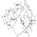
図2は、上記梱包装置の組立状態を示す斜視図である。図1に示すように構成された1枚の段ボールを、図1中に実線で示す折り目は図1に示す状態から上に凸となるように折り曲げ、破線で示す折り目は図1に示す状態から下に凸となるように折り曲げることにより、収納箱が組み立てられる。
【0032】
このとき、図3に示すように、第1底面折曲片1に対して仕切り片3を折り目23が下に凸になるように折り曲げ、仕切り片3に対して仕切り片4を折り目24が上に凸になるように折り曲げ、仕切り片4に対して第2底面折曲片2を折り目25が下に凸になるように折り曲げ、折り目25を折り目23に接触させることにより、第2底面折曲片2が第1底面折曲片1に連続する。
【0033】
また、第1底面折曲片1に対して仕切り片6を折り目28が下に凸になるように折り曲げ、仕切り片6に対して仕切り片7を折り目29が上に凸になるように折り曲げ、仕切り片7に対して第2底面折曲片5を折り目30が下に凸になるように折り曲げ、折り目30を折り目28に接触させることにより、第2底面折曲片5が第1底面折曲片1に連続する。
【0034】
このようにして、第1底面折曲片1の互いに対向する2辺のそれぞれに第2底面折曲片2及び5を連続させて収納箱の底面を構成すると、仕切り片3及び4、並びに、仕切り片6及び7によって、底面から上方に立設する仕切り部材8a,8bが収納箱の内部に形成される。この仕切り部材8a、8bは、背面折曲片19及び前面折曲片20によって構成される収納箱の互いに対向する背面及び前面に対して、間隙を挟んで平行に配置される。このとき、仕切り片3及び4によって構成される仕切り部材8aの上端には2箇所に切り込み61a及び61bが開放し、仕切り片6及び7によって構成される仕切り部材8bの上端には2箇所に切り込み61c及び61dが開放している。
【0035】
切り込み61aには内部折曲片54に形成された切り込み62aが嵌入し、切り込み61bには内部折曲片53に形成された切り込み62bが嵌入し、切り込み61cには内部折曲片54に形成された切り込み62cが嵌入し、切り込み61dには内部折曲片53に形成された切り込み62dが嵌入する。このとき、内部折曲片46が2つの仕切り部材8a,8bの間に位置する。内部折曲片46の下方に脚部舌片43及び脚部折曲片44,45が位置し、内部折曲片46は収納箱の底面に対して高さHの間隙を挟んで平行に配置される。
【0036】
図4は、上記梱包装置によって構成される収納箱の開蓋状態を示す斜視図である。収納箱の内部には、部品収納部9a,9b及び本体収納部9cが形成される。部品収納部9aは、底面折曲片1、側面折曲片22、内部折曲片52、内部折曲片53、仕切り部材8b及び背面折曲片19の間に形成される。本体収納部9cは、内部折曲片46、内部折曲片53、内部折曲片54、仕切り部材8a、仕切り部材8b及び蓋面折曲片56の間に形成される。部品収納部9bは、底面折曲片1、側面折曲片21、内部折曲片50、内部折曲片54、仕切り部材8a及び仕切り部材8bの間に形成される。
【0037】
収納箱の内部において、部品収納部9a、本体収納部9c、及び、部品収納部9bは、仕切り部材8a,8bに平行な方向に、この順に配置される。したがって、本体収納部9cは、収納箱の左右方向について部品収納部9aと部品収納部9bとの間に位置し、収納箱の前後方向について仕切り部材8aと仕切り部材8bとの間に位置する。また、内部折曲片46によって構成される本体収納部9cの底面は、脚部舌片43及び脚部折曲片44,45により、底面折曲片1との間に間隙が設けられている。したがって、本体収納部9cと収納箱の前面、背面、側面及び底面のそれぞれとの間に空間が形成されている。
【0038】
図5は、上記収納箱に対する被収納部品の収納状態を示す図である。一例として、本体収納部9cには可動部等の比較的複雑な構造を有する可搬型テープレコーダの装置本体10aが収納され、部品収納部9aにはACアダプタ10bが収納され、部品収納部9bにはリモコン及びイヤホン等の付属品10cが収納される。また、収納箱の内部において部品収納部9a,9b及び本体収納部9cの上方には、取扱説明書11が収納される。
【0039】
なお、収納箱の内部に被収納部品10a〜10c及び11を収納した後、収納箱の上面が蓋面折曲片56によって閉鎖される。蓋面折曲片56から延出した係止片57は蓋面係止片55の切り込み59に挿入されるとともに、前面折曲片20に形成された係止片58は蓋面折曲片に形成された切り込み60に挿入され、蓋面折曲片56による収納箱の上面の閉鎖状態が維持される。
【0040】
前述のように、本体収納部9cと収納箱の前面、背面、側面及び底面のそれぞれとの間に空間が形成されているため、本体収納部9cに収納された装置本体10aは、収納箱の前面、背面、側面及び底面のそれぞれに直接接触することがない。また、本体収納部9cに収納された装置本体10aの上方には取扱説明書11が収納されていることから、装置本体10aは収納箱の蓋面にも直接接触することがない。
【0041】
したがって、収納箱の内部に収納された装置本体10aは、6面の全面について収納箱の内側面に直接接触することがなく、収納箱の外側面に作用した外力は、部品収納部9a若しくは9b、仕切り部材8aと背面との間き空間、仕切り部材8bと前面との間の空間、内部折曲片46と底面との間の空間、又は、取扱説明書によって緩衝された状態で、装置本体10aに作用する。このため、装置本体10aに大きな外力が直接的に作用することがなく、装置本体10aの損傷や破損を確実に防止することができる。
【0042】
また、本体収納部9cは、収納箱の他の部分を構成する部材とともに1枚の段ボール中に折り目によって形成された部材によって構成されるため、梱包装置の製造のために高価な金型を用いる必要がなく、梱包装置の製造コストを低廉化できるとともに、梱包装置を単一部品によって構成できるため、保管管理や組立作業を容易化することができる。
【0043】
図6は、上記第1の実施形態の別の例に係る梱包装置の要部の構成及び組立状態を示す図である。この例では、仕切り片3及び仕切り片6の第1底面折曲片1側に孔部62及び63を形成し、第2底面折曲片2及び5の仕切り片4及び7側に突起61及び63を形成している。収納箱の組み立て時において、第1底面折曲片1に第2底面折曲片2,5を連続させる際に、突起61及び63のそれぞれを孔部62及び64のそれぞれに嵌入することにより、第1底面折曲片1に対する第2底面折曲片2,5の連続状態を確実に維持することができる。
【0044】
図7は、この発明の応用に係る梱包装置を構成する段ボールの展開図である。1枚の段ボールには、係止片118、収納箱の背面を構成する背面折曲片123、収納箱の一方の側面を構成する側面折曲片124、収納箱の前面を構成する前面折曲片125及び収納箱の他方の側面を構成する側面折曲片125が、それぞれの間に折り目123a〜123dを挟んでこの順に形成されている。
【0045】
背面折曲片123には、折り目127aを挟んで収納箱の蓋面を構成する蓋面折曲片127及び蓋面係止片128が折り目128aとともに延出しており、折り目119aを挟んで収納箱の底面の一部を構成する底面折曲片119が延出している。側面折曲片124には、折り目127bを挟んで第1収納部を構成する内部折曲片129、137及び138が折り目129a及び129bとともに延出しており、折り目119bを挟んで収納箱の底面の一部を構成する底面折曲片120が延出している。前面折曲片125には、折り目127cを挟んで第2及び第3収納部を構成する内部折曲片125、130〜132が折り目130a及び131bとともに延出しており、折り目119cを挟んで収納箱の底面の一部を構成する底面折曲片121が延出している。内部折曲片131には、第2収納部と第3収納部とを分割する中間舌片133が形成されている。側面折曲片126には、折り目127dを挟んで第4収納部(請求項6及び7の第2の収納部に相当する。)を構成する内部折曲片134〜136が折り目134a及び134cとともに延出している。内部折曲片135及び136には、内部折曲片134に連続する突出片142が形成されている。
【0046】
図8は、上記梱包装置の収納箱の組立状態を示す外観図である。梱包装置を構成する1枚の段ボールを複数の折り目において折り曲げ、底面折曲片119〜122を互いに組み合わせることにより、収納箱を組み立てる。このとき、まず、係止片118、背面折曲片123、側面折曲片124、前面折曲片125及び側面折曲片126を折り目123a〜123dにおいて折り曲げるとともに、底面折曲片119〜122を折り目119a〜119dにおいて折り曲げ、底面折曲片119〜122を互いに組み合わせた後、内部折曲片130〜132を折り目127c、130a及び131bにおいて折り曲げ、折り目131aにおいて中間舌片133を折り曲げる。次いで、内部折曲片129、137及び138を折り目127b、129a及び129bにおいて折り曲げる。さらに、内部折曲片134〜136を折り目127d、134a及び134bにおいて折り曲げる。最後に、蓋面折曲片127及び蓋面係止片128を折り目127a及び128aにおいて折り曲げる。
【0047】
図9は、上記梱包装置の収納箱の内部における収納部の配置状態を示す正面断面図である。収納箱の内部には、底面折曲片119〜122の上面に、第1〜第3収納部101〜103が形成されるとともに、第2収納部102及び第3収納部103の上方に第4収納部104が形成される。第1収納部101は、底面折曲片119〜122、側面折曲片124、内部折曲片129、内部折曲片133、前面折曲片125及び背面折曲片123の間に形成される。第2収納部102は、内部折曲片138、内部折曲片137、内部折曲片136、中間舌片132、前面折曲片125及び背面折曲片123の間に形成される。第3収納部103は、内部折曲片131、中間舌片132、内部折曲片136、側面折曲片126、前面折曲片125及び背面折曲片123の間に形成される。第4収納部は、内部折曲片136、内部折曲片137、蓋面折曲片127、内部折曲片135、前面折曲片1125及び背面折曲片123の間に形成される。
【0048】
第1収納部101を構成する内部折曲片133には内部接触片138が連続する内部接触片137が全面にわたって当接しており、内部接触片138の端部は中間舌片132に当接している。このため、収納箱の振動によって第1収納部101に収納された収納物が第2収納部102側に移動した場合にも、第1収納部101の形状が維持され、第1収納部101における収納物の収納状態が維持される。
【0049】
以上の構成により、第2収納部102には、左右に第1収納部101及び第3収納部103が位置し、上部に第4収納部104が位置する。したがって、第2収納部102に収納された被収納部品は、収納箱の2側面及び蓋面に直接接触することがない。このため、収納箱の2側面のいずれか又は蓋面に作用した外力は、第1収納部101、第3収納部103又は第4収納部において緩衝された状態で第2収納部102に収納された被収納部品に作用し、第2収納部102に収納された被収納部品に大きな外力が直接的に作用することがなく、被収納部品の損傷や破損を防止することができる。
【0050】
また、1枚の段ボール内に形成された折曲片を最大3回折り曲げることのみにより、収納箱の内部に4つの収納部のそれぞれを極めて容易に構成することができ、収納箱の組立作業を簡略化することができる。
【0051】
さらに、主として取扱説明書等の薄型の収納物が収納される第4収納部104では、収納箱の底面及び蓋面に平行に配置された内部折曲片136に対して所定の間隙を挟んで平行に突出片142が突出しており、収納物は内部折曲片136と突出片142との間に挟持された状態で収納される。したがって、収納箱の上面を蓋面折曲片127によって閉鎖した状態で、収納箱が振動した場合にも、薄型の収納物が第4収納部104から収納箱の外部に露出することがなく、収納物を確実に収納することができる。
【0052】
また、図10に示すように、突出片142が第4収納部104の底面を構成する内部折曲片136に内部折曲片134及び135を介して一体的に形成されていることから、第4収納部104の底面は突出片142と一体に移動する。したがって、蓋面折曲片127が収納箱の上面を開放している状態で突出片142を矢印A方向に回転させると、収納物を載置した内部折曲片136が突出片142とともに回転し、収納物を極めて容易に取り出すことができる。
【0053】
なお、図9に示すように、第4収納部104の底面を構成する内部折曲片136の長さL1を、内部折曲片136の端部から側面折曲片126までの長さL3から内部折曲片134の長さL2を差し引いた長さよりも長くすることにより、収納箱の寸法を変えることなく第4収納部104における収納寸法を長くすることができる。
【0054】
【発明の効果】
請求項1に記載した発明によれば、1枚の段ボールを折り目で折り曲げるとともに、第1底面折曲片が構成する底面の一部に第2底面折曲片が構成する底面の他の一部を連続させて収納箱の内部に側面に対して間隙を挟んで平行に配置された仕切り部材を形成することにより、仕切り部材を挟んで側面との間隙の反対側に収納した被収納部品が側面に直接接触しないようにし、被収納部品に対する側面からの外力を仕切り部材と側面との間の間隙において緩衝させることができ、被収納部品を損傷や破損を生じることのない状態で収納する収納部を1枚の段ボールによって構成することができ、組立作業を容易にすることができるとともに、保管管理を簡略化することができる。
【0056】
また、1枚の段ボールを折り目で折り曲げるとともに、第1底面折曲片が構成する底面の一部に第2底面折曲片が構成する底面の他の一部を連続させて収納箱の内部に側面に対して間隙を挟んで平行に配置された仕切り部材を形成するとともに、他の側面に近接して配置された部品収納部を形成することにより、部品収納部及び仕切り部材の内側に収納した被収納部品が、部品収納部が近接する側面及び仕切り部材に平行な側面に直接接触しないようにし、被収納部品に対する側面からの外力を仕切り部材と側面との間の間隙、及び、部品収納部において緩衝させることができ、被収納部品を損傷や破損を生じることのない状態で収納する収納部を1枚の段ボールによって構成することができ、組立作業を容易にすることができるとともに、保管管理を簡略化することができる。
また、1枚の段ボールを折り目で折り曲げるとともに、第1底面折曲片が構成する底面の一部に第2底面折曲片が構成する底面の他の一部を連続させて収納箱の内部に側面に対して間隙を挟んで平行に配置された仕切り部材を形成するとともに、他の側面に近接して配置された部品収納部を形成し、さらに、仕切り部材の内側に底面に対して間隙を挟んで平行に配置された載置部材を形成することにより、部品収納部及び仕切り部材の内側で載置部材上に載置して収納した被収納部品が、部品収納部が近接する側面、仕切り部材に平行な側面、及び、底面に直接接触しないようにし、被収納部品に対する側面及び底面からの外力を仕切り部材と側面との間の間隙、部品収納部、及び、載置部材と底面との間の間隙において緩衝させることができ、被収納部品を損傷や破損を生じることのない状態で収納する収納部を1枚の段ボールによって構成することができ、組立作業を容易にすることができるとともに、保管管理を簡略化することができる。
【0057】
また、この発明によれば、1枚の段ボールを折り目で折り曲げるとともに、第1底面折曲片が構成する底面の一部に第2底面折曲片が構成する底面の他の一部を連続させて収納箱の内部に側面に対して間隙を挟んで平行に配置された仕切り部材を形成するとともに、他の2つの側面に近接して配置された2個の部品収納部を形成することにより、2個の部品収納部及び仕切り部材の内側に収納した被収納部品が、部品収納部が近接する2側面及び仕切り部材に平行な側面に直接接触しないようにし、被収納部品に対する側面からの外力を仕切り部材と側面との間の間隙、及び、2個の部品収納部において緩衝させることができ、被収納部品を損傷や破損を生じることのない状態で収納する収納部を1枚の段ボールによって構成することができ、組立作業を容易にすることができるとともに、保管管理を簡略化することができる。
【図面の簡単な説明】
【図1】この発明の第1の実施形態に係る梱包装置を構成する段ボールの展開図である。
【図2】上記梱包装置の組立状態を示す斜視図である。
【図3】上記梱包装置の要部の組立時における状態を示す図である。
【図4】上記梱包装置によって構成される収納箱の開蓋状態を示す斜視図である。
【図5】上記収納箱に対する被収納部品の収納状態を示す図である。
【図6】上記第1の実施形態の別の例に係る梱包装置の要部の構成及び組立状態を示す図である。
【図7】この発明の応用に係る梱包装置を構成する段ボールの展開図である。
【図8】上記梱包装置の収納箱の組立状態を示す外観図である。
【図9】上記梱包装置の収納箱の内部における収納部の配置状態を示す正面断面図である。
【図10】上記梱包装置の収納箱の開蓋時における収納物の収納状態を示す図である。
【図11】従来の梱包装置の第1の構成を示す図である。
【図12】従来の梱包装置の第2の構成を示す図である。
【図13】上記第2の構成に係る従来の梱包装置の組立状態を示す図である。
【符号の説明】
1−第1底面折曲片
2,5−第2底面折曲片
3,4,5,6−仕切り片
9a,9c−部品収納部
9b−本体収納部
19−背面折曲片
20−全面折曲片
21,22−側面折曲片
23〜24−折り目
28〜32−折り目
33〜35−折り目
37,38−折り目[0001]
[Industrial application fields]
The present invention relates to a packaging device that forms a hollow hexahedron storage box for storing a plurality of components to be stored therein by bending a cardboard cut into a predetermined shape at a predetermined position.
[0002]
[Prior art]
As products that are traded in the market, there are products that are transported and sold by storing replacement parts and accessories together with the main body in a single storage box. For example, in electrical products such as portable tape recorders and CD players, AC adapters that perform AC / DC conversion of power to the main unit, and accessories such as earphones that are connected to terminals of the main unit, together with the main unit Stored in a single storage box. When storing a plurality of stored parts in a single storage box in this way, the stored parts in the storage box should not be damaged or damaged due to a plurality of stored parts coming into contact with each other during transportation. It is necessary to regulate the movement of each.
[0003]
In addition, the storage box is often formed using a relatively thin material, and the storage box itself cannot be expected to have a sufficient buffer function. For this reason, it is necessary to prevent external force from acting on each surface of the storage box, particularly for parts having a complicated structure such as a movable part such as the main body of the apparatus. Must be held in direct contact with the inner surface.
[0004]
Therefore, as shown in FIG. 11, as a packaging device for storing a plurality of stored parts, a plurality of recesses are formed in accordance with the shapes of the plurality of stored parts such as the apparatus
[0005]
However, since the packing device shown in FIG. 11 uses the
[0006]
Therefore, as shown in FIG. 12, there is a packaging device constituted by a
[0007]
When assembling this packing device, as shown in FIG. 13, after inserting the
[0008]
As a result, a
[0009]
Furthermore, the entire packaging device can be constructed using corrugated cardboard that can be easily recycled, discarded and molded, and can be folded into a thin plate shape, thereby reducing costs during manufacturing, transportation and storage. Can be easily adapted to environmental problems.
[0010]
[Problems to be solved by the invention]
However, in the packaging device shown in FIG. 12, in order to form the same number of storage parts as the number of components to be stored in the
[0011]
An object of the present invention is that a single member made of cardboard can be used to form a storage unit that stores components to be stored without causing damage or breakage, thereby facilitating assembly work. Another object of the present invention is to provide a packaging device that can simplify storage management and assembly work.
[0012]
[Means for Solving the Problems]
According to the first aspect of the present invention, a hollow hexahedron that houses a single or a plurality of components to be accommodated therein is formed by forming folds at a plurality of predetermined positions in one cardboard and folding the cardboard at the folds. In the packaging device constituting the storage box,
A first bottom surface bent piece constituting a part of the bottom surface of the storage box and a second bottom surface bent piece constituting the other part continuous with a part of the bottom surface of the storage box constituted by the first bottom surface bent piece; Between, the partition piece constituting the partition member disposed in parallel with the gap to the side surface inside the storage box is disposed through the fold line,
Side folds constituting the side surface of the storage box from the side where the other part of the bottom surface of the storage box formed by the second bottom surface bent piece is not continuous in a part of the bottom surface of the storage box formed by the first bottom surface bent piece The bent pieces and the inner bent pieces constituting the component storage section between the side faces of the side bent pieces constituting the inside of the storage box, and the folds are arranged between them to extend.
A mounting piece constituting a mounting member arranged in parallel with a gap to the bottom surface inside the partition member inside the storage box is extended from the internal bent piece through a fold. .
The invention described in
In a packaging device constituting a hollow hexahedron storage box for storing a single or a plurality of stored parts inside by folding the cable at the fold line,
A first bottom surface bent piece constituting a part of the bottom surface of the storage box and a second bottom surface bent piece constituting the other part continuous with a part of the bottom surface of the storage box constituted by the first bottom surface bent piece; Between, the partition piece constituting the partition member disposed in parallel with the gap to the side surface inside the storage box is disposed through the fold line,
Storage from each of two sides where the other part of the bottom surface of the storage box formed by each of the two second bottom surface bent pieces is not continuous in a part of the bottom surface of the storage box formed by the first bottom surface bent piece. The side bent pieces constituting the side surfaces of the box and the inner bent pieces constituting the component storage portion between the side bent pieces inside the storage box and the side faces constituting the side bent pieces, Place and extend,
A mounting piece constituting a mounting member arranged in parallel with a gap to the bottom surface inside the partition member inside the storage box is extended from the internal bent piece through a fold. .
Further, according to the invention described in
A side bent piece constituting one side surface of the storage box is disposed in parallel with the lid surface between the upper side of the first storage portion formed in the storage box and the lid surface with a gap between them, An extension piece forming the bottom surface of the second storage part is extended through the crease;
A protruding piece that protrudes in parallel with a gap with respect to the bottom surface of the second storage portion is formed on a part of the extension piece other than the portion constituting the bottom surface of the second storage portion via a crease and a cut. And
In the second storage section, the inner bent piece, which is a part constituting the bottom surface of the second storage section, is bent at an acute angle of the fold of the inner bent section without changing the dimensions of the storage box. It is characterized by a longer storage dimension.
[0026]
DETAILED DESCRIPTION OF THE INVENTION
FIG. 1 is an exploded view of a cardboard constituting a packaging device according to a first embodiment of the present invention. A rectangular first bottom surface bent
[0027]
Further, the side bent
[0028]
1 is a fold that is bent so as to protrude upward from the state shown in FIG. 1, and a fold indicated by a broken line is bent so as to protrude downward from the state shown in FIG. It is a crease.
[0029]
The
[0030]
[0031]
FIG. 2 is a perspective view showing an assembled state of the packaging device. 1 is folded so that the fold shown by a solid line in FIG. 1 is convex upward from the state shown in FIG. 1, and the fold shown by a broken line is from the state shown in FIG. The storage box is assembled by bending it so as to protrude downward.
[0032]
At this time, as shown in FIG. 3, the
[0033]
Further, the
[0034]
In this way, when the bottom surface of the storage box is configured by connecting the second bottom surface bent
[0035]
A
[0036]
FIG. 4 is a perspective view showing an open state of a storage box constituted by the packaging device. In the storage box,
[0037]
Inside the storage box, the
[0038]
FIG. 5 is a diagram illustrating a storage state of the components to be stored in the storage box. As an example, the main
[0039]
In addition, after storing the to-
[0040]
As described above, since spaces are formed between the main
[0041]
Therefore, the apparatus
[0042]
Moreover, since the main
[0043]
FIG. 6 is a diagram illustrating a configuration and an assembled state of main parts of a packaging device according to another example of the first embodiment. In this example, holes 62 and 63 are formed on the first bottom surface bent
[0044]
FIG. 7 shows the present invention.applicationIt is an expanded view of the cardboard which comprises the packing apparatus which concerns on. One corrugated cardboard includes a
[0045]
In the back
[0046]
FIG. 8 is an external view showing an assembled state of the storage box of the packing device. A storage box is assembled by bending one cardboard constituting the packaging device at a plurality of folds and combining the bottom
[0047]
FIG. 9 is a front cross-sectional view showing an arrangement state of the storage portion inside the storage box of the packing device. Inside the storage box, first to
[0048]
An
[0049]
With the above configuration, in the
[0050]
In addition, each of the four storage portions can be configured very easily inside the storage box only by bending the bent piece formed in one cardboard up to three times. It can be simplified.
[0051]
Furthermore, in the
[0052]
Further, as shown in FIG. 10, the protruding
[0053]
As shown in FIG. 9, the length L <b> 1 of the internal
[0054]
【The invention's effect】
According to the first aspect of the present invention, one cardboard is folded at a fold, and another part of the bottom surface formed by the second bottom surface bent piece is formed on a part of the bottom surface formed by the first bottom surface bent piece. By forming a partition member arranged in parallel with a gap with respect to the side surface inside the storage box, the parts to be stored stored on the opposite side of the gap from the side surface with the partition member interposed therebetween A storage unit that can absorb external force from the side surface to the stored component in the gap between the partition member and the side surface, and stores the stored component without causing damage or breakage. Can be constituted by a single cardboard, which facilitates the assembling work and simplifies storage management.
[0056]
Also,One cardboard is folded at the crease, and another part of the bottom surface formed by the second bottom surface bent piece is made continuous with a part of the bottom surface formed by the first bottom surface bent piece on the side surface inside the storage box. On the other hand, a partition member arranged in parallel with a gap is formed, and a component storage portion disposed close to the other side surface is formed, so that the component storage portion and the object to be stored stored inside the partition member are formed. Prevents the component from directly contacting the side surface close to the component storage unit and the side surface parallel to the partition member, and cushions the external force from the side surface to the stored component in the gap between the partition member and the side surface and the component storage unit. The storage part that stores the stored parts in a state that does not cause damage or breakage can be constituted by a single cardboard, facilitating the assembly work, and the storage tube It is possible to simplify the.
In addition, the cardboard is folded at the crease, and the other part of the bottom surface formed by the second bottom surface bent piece is made continuous with the part of the bottom surface formed by the first bottom surface bent piece inside the storage box. A partition member arranged in parallel to the side surface with a gap therebetween is formed, a component storage portion arranged in proximity to the other side surface is formed, and further, a gap with respect to the bottom surface is formed inside the partition member. By forming the mounting members arranged in parallel with the sandwiched parts, the parts to be stored placed and stored on the mounting members inside the component storage part and the partition member, the side surface where the part storage part is close, the partition The external force from the side surface and the bottom surface on the side surface parallel to the member and the bottom surface, the gap between the partition member and the side surface, the component storage portion, and the mounting member and the bottom surface Can be buffered in the gap between The storage unit for storing the stored parts in a state that does not cause damage or breakage can be constituted by a single cardboard, facilitating assembly work and simplifying storage management. it can.
[0057]
Also thisAccording to the invention, a cardboard is folded at a crease, and another part of the bottom surface formed by the second bottom surface bent piece is made to be continuous with a part of the bottom surface formed by the first bottom surface bent piece to store the box. Forming a partition member disposed in parallel with the side surface with a gap between the two side surfaces, and forming two component storage portions disposed in proximity to the other two side surfaces. The parts to be stored stored inside the part storage part and the partition member are prevented from coming into direct contact with the two side surfaces close to the part storage part and the side surface parallel to the partition member, and the external force from the side surface with respect to the stored parts is separated from the partition member. The space between the side surfaces and the two component storage portions can be buffered, and the storage portion for storing the storage target components without causing damage or breakage can be constituted by a single cardboard. And assembly work It is possible to facilitate, it is possible to simplify the storage management.
[Brief description of the drawings]
FIG. 1 is an exploded view of a cardboard constituting a packaging device according to a first embodiment of the present invention.
FIG. 2 is a perspective view showing an assembled state of the packing device.
FIG. 3 is a diagram showing a state of the main part of the packaging device during assembly.
FIG. 4 is a perspective view showing an open state of a storage box constituted by the packing device.
FIG. 5 is a diagram illustrating a storage state of a component to be stored in the storage box.
FIG. 6 is a diagram showing a configuration and an assembled state of a main part of a packaging device according to another example of the first embodiment.
FIG. 7 shows the present invention.applicationIt is an expanded view of the cardboard which comprises the packing apparatus which concerns on.
FIG. 8 is an external view showing an assembled state of a storage box of the packing device.
FIG. 9 is a front cross-sectional view showing an arrangement state of the storage portion inside the storage box of the packing device.
FIG. 10 is a diagram showing a stored state of stored items when the storage box of the packing device is opened.
FIG. 11 is a diagram showing a first configuration of a conventional packing device.
FIG. 12 is a diagram showing a second configuration of a conventional packaging device.
FIG. 13 is a view showing an assembled state of the conventional packaging device according to the second configuration.
[Explanation of symbols]
1-first bottom bent piece
2,5-second bottom bent piece
3,4,5,6-partition
9a, 9c-component storage
9b-body storage
19-Back folded piece
20-Fully folded piece
21,22 side folds
23-24-Crease
28-32-crease
33-35-crease
37, 38-crease
Claims (2)
収納箱の底面の一部を構成する第1底面折曲片と第1底面折曲片が構成する収納箱の底面の一部に連続する他の一部を構成する第2底面折曲片との間に、収納箱の内部で側面に対して間隙を挟んで平行に配置される仕切り部材を構成する仕切り片を折り目を介して配置し、
第1底面折曲片が構成する収納箱の底面の一部において第2底面折曲片が構成する収納箱の底面の他の一部が連続しない辺から、収納箱の側面を構成する側面折曲片、及び、収納箱の内部で側面折曲片が構成する側面との間に部品収納部を構成する内部折曲片を、それぞれの間に折り目を配置して延出し、
収納箱の内部の仕切り部材の内側で底面に対して間隙を挟んで平行に配置される載置部材を構成する載置片を折り目を介して内部折曲片から延出したことを特徴とする梱包装置。In a packaging device that forms a hollow hexahedron storage box for storing a single or a plurality of components to be stored therein by forming folds at a plurality of predetermined positions in one cardboard and bending the cardboard at the folds. ,
A first bottom surface bent piece constituting a part of the bottom surface of the storage box and a second bottom surface bent piece constituting the other part continuous with a part of the bottom surface of the storage box constituted by the first bottom surface bent piece; Between, the partition piece constituting the partition member disposed in parallel with the gap to the side surface inside the storage box is disposed through the fold line,
Side folds constituting the side surface of the storage box from the side where the other part of the bottom surface of the storage box formed by the second bottom surface bent piece is not continuous in a part of the bottom surface of the storage box formed by the first bottom surface bent piece The bent pieces and the inner bent pieces constituting the component storage section between the side faces of the side bent pieces constituting the inside of the storage box, and the folds are arranged between them to extend.
A mounting piece constituting a mounting member arranged in parallel with a gap to the bottom surface inside the partition member inside the storage box is extended from the internal bent piece through a fold. Packing equipment.
収納箱の底面の一部を構成する第1底面折曲片と第1底面折曲片が構成する収納箱の底面の一部に連続する他の一部を構成する第2底面折曲片との間に、収納箱の内部で側面に対して間隙を挟んで平行に配置される仕切り部材を構成する仕切り片を折り目を介して配置し、
第1底面折曲片が構成する収納箱の底面の一部において2個の第2底面折曲片のそれぞれが構成する収納箱の底面の他の一部が連続しない2辺のそれぞれから、収納箱の側面を構成する側面折曲片、及び、収納箱の内部で側面折曲片が構成する側面のそれぞれとの間に部品収納部を構成する内部折曲片を、それぞれの間に折り目を配置して延出し、
収納箱の内部の仕切り部材の内側で底面に対して間隙を挟んで平行に配置される載置部材を構成する載置片を折り目を介して内部折曲片から延出したことを特徴とする梱包装置。In a packaging device that forms a hollow hexahedron storage box for storing a single or a plurality of components to be stored therein by forming folds at a plurality of predetermined positions in one cardboard and bending the cardboard at the folds. ,
A first bottom surface bent piece constituting a part of the bottom surface of the storage box and a second bottom surface bent piece constituting the other part continuous with a part of the bottom surface of the storage box constituted by the first bottom surface bent piece; Between, the partition piece constituting the partition member disposed in parallel with the gap to the side surface inside the storage box is disposed through the fold line,
Storage from each of two sides where the other part of the bottom surface of the storage box formed by each of the two second bottom surface bent pieces is not continuous in a part of the bottom surface of the storage box formed by the first bottom surface bent piece. The side bent pieces constituting the side surfaces of the box and the inner bent pieces constituting the component storage portion between the side bent pieces inside the storage box and the side faces constituting the side bent pieces, Place and extend,
A mounting piece constituting a mounting member arranged in parallel with a gap to the bottom surface inside the partition member inside the storage box is extended from the internal bent piece through a fold. Packing equipment.
Priority Applications (1)
| Application Number | Priority Date | Filing Date | Title |
|---|---|---|---|
| JP22189098A JP3655472B2 (en) | 1998-08-05 | 1998-08-05 | Packing equipment |
Applications Claiming Priority (1)
| Application Number | Priority Date | Filing Date | Title |
|---|---|---|---|
| JP22189098A JP3655472B2 (en) | 1998-08-05 | 1998-08-05 | Packing equipment |
Publications (2)
| Publication Number | Publication Date |
|---|---|
| JP2000053122A JP2000053122A (en) | 2000-02-22 |
| JP3655472B2 true JP3655472B2 (en) | 2005-06-02 |
Family
ID=16773789
Family Applications (1)
| Application Number | Title | Priority Date | Filing Date |
|---|---|---|---|
| JP22189098A Expired - Lifetime JP3655472B2 (en) | 1998-08-05 | 1998-08-05 | Packing equipment |
Country Status (1)
| Country | Link |
|---|---|
| JP (1) | JP3655472B2 (en) |
Family Cites Families (4)
| Publication number | Priority date | Publication date | Assignee | Title |
|---|---|---|---|---|
| JPH0323023U (en) * | 1989-07-19 | 1991-03-11 | ||
| JPH0671417U (en) * | 1993-03-15 | 1994-10-07 | アイワ株式会社 | Cosmetic case for electric appliances |
| JPH10194269A (en) * | 1996-12-27 | 1998-07-28 | Maruichi:Kk | Corrugated fiberboard packaging box |
| JP3046690U (en) * | 1997-08-29 | 1998-03-10 | 元▲薫▼ 劉 | Partitioned paper container with lid |
-
1998
- 1998-08-05 JP JP22189098A patent/JP3655472B2/en not_active Expired - Lifetime
Also Published As
| Publication number | Publication date |
|---|---|
| JP2000053122A (en) | 2000-02-22 |
Similar Documents
| Publication | Publication Date | Title |
|---|---|---|
| JP3985268B2 (en) | Electronic equipment packaging box | |
| JP3018068B2 (en) | Foldable packing box with double wall structure | |
| JP3655472B2 (en) | Packing equipment | |
| JP3340676B2 (en) | Packing equipment | |
| JPH10211967A (en) | Packing formed of corrugated cardboard | |
| JP2006076585A (en) | Packaging box | |
| JP3387297B2 (en) | Packaging equipment | |
| JP2002179057A (en) | Packaging box | |
| JP3987835B2 (en) | Electronic equipment packaging box | |
| JP4377372B2 (en) | Bundled case and packing device | |
| JP3204993B2 (en) | Packaging box | |
| JP3101289U (en) | Cushioning material for packaging of accessories for electrical products | |
| JP4272569B2 (en) | Packaging cushion | |
| JP2579549Y2 (en) | Product protection cushioning material | |
| JP3248572B2 (en) | Packing material assembly | |
| JP2539104Y2 (en) | Packaging structure for products with lids | |
| JP2004106923A (en) | Packaging implement | |
| JP3429201B2 (en) | Package | |
| JPS6333275A (en) | Packer | |
| JPH11348965A (en) | Cushion member of packaging device | |
| JP2002002673A (en) | Packaging box | |
| US20060289332A1 (en) | Package assembly | |
| JPH10236465A (en) | Bottom lid for packing box | |
| JPH10236466A (en) | Bottom lid for packing box | |
| JP2019218101A (en) | Packaging container and sheet member for packaging container |
Legal Events
| Date | Code | Title | Description |
|---|---|---|---|
| A977 | Report on retrieval |
Free format text: JAPANESE INTERMEDIATE CODE: A971007 Effective date: 20040225 |
|
| A131 | Notification of reasons for refusal |
Free format text: JAPANESE INTERMEDIATE CODE: A131 Effective date: 20040302 |
|
| A521 | Written amendment |
Free format text: JAPANESE INTERMEDIATE CODE: A523 Effective date: 20040430 |
|
| A02 | Decision of refusal |
Free format text: JAPANESE INTERMEDIATE CODE: A02 Effective date: 20041102 |
|
| A521 | Written amendment |
Free format text: JAPANESE INTERMEDIATE CODE: A523 Effective date: 20041202 |
|
| A911 | Transfer of reconsideration by examiner before appeal (zenchi) |
Free format text: JAPANESE INTERMEDIATE CODE: A911 Effective date: 20050106 |
|
| TRDD | Decision of grant or rejection written | ||
| A01 | Written decision to grant a patent or to grant a registration (utility model) |
Free format text: JAPANESE INTERMEDIATE CODE: A01 Effective date: 20050222 |
|
| A61 | First payment of annual fees (during grant procedure) |
Free format text: JAPANESE INTERMEDIATE CODE: A61 Effective date: 20050303 |
|
| R150 | Certificate of patent or registration of utility model |
Free format text: JAPANESE INTERMEDIATE CODE: R150 |
|
| FPAY | Renewal fee payment (event date is renewal date of database) |
Free format text: PAYMENT UNTIL: 20080311 Year of fee payment: 3 |
|
| FPAY | Renewal fee payment (event date is renewal date of database) |
Free format text: PAYMENT UNTIL: 20090311 Year of fee payment: 4 |
|
| FPAY | Renewal fee payment (event date is renewal date of database) |
Free format text: PAYMENT UNTIL: 20100311 Year of fee payment: 5 |
|
| FPAY | Renewal fee payment (event date is renewal date of database) |
Free format text: PAYMENT UNTIL: 20100311 Year of fee payment: 5 |
|
| FPAY | Renewal fee payment (event date is renewal date of database) |
Free format text: PAYMENT UNTIL: 20110311 Year of fee payment: 6 |
|
| FPAY | Renewal fee payment (event date is renewal date of database) |
Free format text: PAYMENT UNTIL: 20120311 Year of fee payment: 7 |
|
| FPAY | Renewal fee payment (event date is renewal date of database) |
Free format text: PAYMENT UNTIL: 20120311 Year of fee payment: 7 |
|
| FPAY | Renewal fee payment (event date is renewal date of database) |
Free format text: PAYMENT UNTIL: 20130311 Year of fee payment: 8 |