JP3654792B2 - Wire harness device - Google Patents
Wire harness device Download PDFInfo
- Publication number
- JP3654792B2 JP3654792B2 JP13171199A JP13171199A JP3654792B2 JP 3654792 B2 JP3654792 B2 JP 3654792B2 JP 13171199 A JP13171199 A JP 13171199A JP 13171199 A JP13171199 A JP 13171199A JP 3654792 B2 JP3654792 B2 JP 3654792B2
- Authority
- JP
- Japan
- Prior art keywords
- current value
- load
- wire harness
- circuit
- wire
- Prior art date
- Legal status (The legal status is an assumption and is not a legal conclusion. Google has not performed a legal analysis and makes no representation as to the accuracy of the status listed.)
- Expired - Fee Related
Links
- 238000010438 heat treatment Methods 0.000 claims description 42
- 238000002844 melting Methods 0.000 claims description 22
- 230000008018 melting Effects 0.000 claims description 22
- 238000001514 detection method Methods 0.000 claims description 21
- 229920005989 resin Polymers 0.000 claims description 10
- 239000011347 resin Substances 0.000 claims description 10
- 239000000463 material Substances 0.000 claims description 9
- 230000000903 blocking effect Effects 0.000 claims description 8
- 238000003825 pressing Methods 0.000 claims description 2
- 239000003795 chemical substances by application Substances 0.000 description 19
- 229910052751 metal Inorganic materials 0.000 description 14
- 239000002184 metal Substances 0.000 description 14
- 238000010586 diagram Methods 0.000 description 12
- 239000003832 thermite Substances 0.000 description 11
- 239000000779 smoke Substances 0.000 description 8
- 230000002159 abnormal effect Effects 0.000 description 7
- 230000006835 compression Effects 0.000 description 6
- 238000007906 compression Methods 0.000 description 6
- 239000004020 conductor Substances 0.000 description 6
- AMWRITDGCCNYAT-UHFFFAOYSA-L hydroxy(oxo)manganese;manganese Chemical compound [Mn].O[Mn]=O.O[Mn]=O AMWRITDGCCNYAT-UHFFFAOYSA-L 0.000 description 6
- XEEYBQQBJWHFJM-UHFFFAOYSA-N iron Substances [Fe] XEEYBQQBJWHFJM-UHFFFAOYSA-N 0.000 description 5
- WABPQHHGFIMREM-UHFFFAOYSA-N lead(0) Chemical compound [Pb] WABPQHHGFIMREM-UHFFFAOYSA-N 0.000 description 5
- UQSXHKLRYXJYBZ-UHFFFAOYSA-N Iron oxide Chemical compound [Fe]=O UQSXHKLRYXJYBZ-UHFFFAOYSA-N 0.000 description 4
- 229910052802 copper Inorganic materials 0.000 description 4
- 239000010949 copper Substances 0.000 description 4
- 230000020169 heat generation Effects 0.000 description 4
- RYGMFSIKBFXOCR-UHFFFAOYSA-N Copper Chemical compound [Cu] RYGMFSIKBFXOCR-UHFFFAOYSA-N 0.000 description 3
- 229910000881 Cu alloy Inorganic materials 0.000 description 3
- 230000005856 abnormality Effects 0.000 description 3
- 229910052782 aluminium Inorganic materials 0.000 description 2
- 238000005304 joining Methods 0.000 description 2
- 229910000679 solder Inorganic materials 0.000 description 2
- 238000003860 storage Methods 0.000 description 2
- 229910052718 tin Inorganic materials 0.000 description 2
- QPLDLSVMHZLSFG-UHFFFAOYSA-N CuO Inorganic materials [Cu]=O QPLDLSVMHZLSFG-UHFFFAOYSA-N 0.000 description 1
- 229910005347 FeSi Inorganic materials 0.000 description 1
- WGLPBDUCMAPZCE-UHFFFAOYSA-N Trioxochromium Chemical compound O=[Cr](=O)=O WGLPBDUCMAPZCE-UHFFFAOYSA-N 0.000 description 1
- PNEYBMLMFCGWSK-UHFFFAOYSA-N aluminium oxide Inorganic materials [O-2].[O-2].[O-2].[Al+3].[Al+3] PNEYBMLMFCGWSK-UHFFFAOYSA-N 0.000 description 1
- 239000000440 bentonite Substances 0.000 description 1
- 229910000278 bentonite Inorganic materials 0.000 description 1
- SVPXDRXYRYOSEX-UHFFFAOYSA-N bentoquatam Chemical compound O.O=[Si]=O.O=[Al]O[Al]=O SVPXDRXYRYOSEX-UHFFFAOYSA-N 0.000 description 1
- 238000007664 blowing Methods 0.000 description 1
- 229910052796 boron Inorganic materials 0.000 description 1
- 239000011651 chromium Substances 0.000 description 1
- 229910000423 chromium oxide Inorganic materials 0.000 description 1
- 238000005520 cutting process Methods 0.000 description 1
- 230000000694 effects Effects 0.000 description 1
- 239000011810 insulating material Substances 0.000 description 1
- 229910052745 lead Inorganic materials 0.000 description 1
- YADSGOSSYOOKMP-UHFFFAOYSA-N lead dioxide Inorganic materials O=[Pb]=O YADSGOSSYOOKMP-UHFFFAOYSA-N 0.000 description 1
- 238000004519 manufacturing process Methods 0.000 description 1
- 229910044991 metal oxide Inorganic materials 0.000 description 1
- 150000004706 metal oxides Chemical class 0.000 description 1
- 238000000034 method Methods 0.000 description 1
- 239000000203 mixture Substances 0.000 description 1
- 239000000843 powder Substances 0.000 description 1
- 230000001681 protective effect Effects 0.000 description 1
- 239000000454 talc Substances 0.000 description 1
- 229910052623 talc Inorganic materials 0.000 description 1
- 229920005992 thermoplastic resin Polymers 0.000 description 1
- 229910052719 titanium Inorganic materials 0.000 description 1
- 229910052725 zinc Inorganic materials 0.000 description 1
- 229910052726 zirconium Inorganic materials 0.000 description 1
Images


Classifications
-
- H—ELECTRICITY
- H01—ELECTRIC ELEMENTS
- H01H—ELECTRIC SWITCHES; RELAYS; SELECTORS; EMERGENCY PROTECTIVE DEVICES
- H01H37/00—Thermally-actuated switches
- H01H37/74—Switches in which only the opening movement or only the closing movement of a contact is effected by heating or cooling
- H01H37/76—Contact member actuated by melting of fusible material, actuated due to burning of combustible material or due to explosion of explosive material
- H01H37/761—Contact member actuated by melting of fusible material, actuated due to burning of combustible material or due to explosion of explosive material with a fusible element forming part of the switched circuit
- H01H2037/762—Contact member actuated by melting of fusible material, actuated due to burning of combustible material or due to explosion of explosive material with a fusible element forming part of the switched circuit using a spring for opening the circuit when the fusible element melts
-
- H—ELECTRICITY
- H01—ELECTRIC ELEMENTS
- H01H—ELECTRIC SWITCHES; RELAYS; SELECTORS; EMERGENCY PROTECTIVE DEVICES
- H01H85/00—Protective devices in which the current flows through a part of fusible material and this current is interrupted by displacement of the fusible material when this current becomes excessive
- H01H85/02—Details
- H01H85/46—Circuit arrangements not adapted to a particular application of the protective device
- H01H2085/466—Circuit arrangements not adapted to a particular application of the protective device with remote controlled forced fusing
-
- H—ELECTRICITY
- H02—GENERATION; CONVERSION OR DISTRIBUTION OF ELECTRIC POWER
- H02H—EMERGENCY PROTECTIVE CIRCUIT ARRANGEMENTS
- H02H3/00—Emergency protective circuit arrangements for automatic disconnection directly responsive to an undesired change from normal electric working condition with or without subsequent reconnection ; integrated protection
- H02H3/08—Emergency protective circuit arrangements for automatic disconnection directly responsive to an undesired change from normal electric working condition with or without subsequent reconnection ; integrated protection responsive to excess current
- H02H3/087—Emergency protective circuit arrangements for automatic disconnection directly responsive to an undesired change from normal electric working condition with or without subsequent reconnection ; integrated protection responsive to excess current for DC applications
Landscapes
- Chemical & Material Sciences (AREA)
- Engineering & Computer Science (AREA)
- Combustion & Propulsion (AREA)
- Emergency Protection Circuit Devices (AREA)
- Connection Or Junction Boxes (AREA)
- Fuses (AREA)
Description
【0001】
【発明の属する技術分野】
本発明は、バッテリから負荷への電流が過電流となったときに回路を遮断する過電流保護装置を備えたワイヤーハーネス装置に関する。
【0002】
【従来の技術】
車両に設けられる電装システムでは、パワーウインドウ等の負荷に何らかの異常が発生したり、バッテリーと各負荷とを接続している複数の電線によって構成されたワイヤーハーネス等に何らかの異常が発生したとき、バッテリーと、ワイヤーハーネスとの間に介挿されたヒューズを溶断させて、バッテリーと、ワイヤーハーネスとの間を遮断する各種の保護装置が開発されている。
【0003】
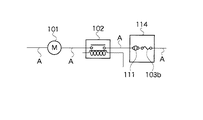
図9は過電流保護装置を備えたワイヤーハーネス装置の一例を示す回路図である。図9に示すワイヤーハーネス装置は、図示しない電源と負荷であるモータ101を接続する回路を備え、スローブローヒューズまたはヒュージブルリンクと比較して応答性の早いブレードヒューズ103bと、PTC素子111とを直列に接続した回路を有する過電流保護装置114を設けている。また、電線Aは、図示しない電源とモータ101とリレー102と過電流保護装置114とを接続している。
【0004】
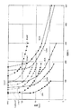
図10に、図9のワイヤーハーネス装置の回路に対応する電流−応答時間特性を示す。図10では、過電流保護装置114により得られる保護特性115と、電線Aとモータ101の電流特性107及びリレー102の過電流特性108とを比較した。点Pはブレードヒューズ103bの保護特性とPTC素子111の保護特性とが交わる点を示し、この点Pよりも右の領域はPTC素子111が前記回路を保護し、点Pよりも左の領域はブレードヒューズ103bが前記回路を保護している。また、107はモータ101にかかる電流特性で、108はリレーにかかる過電流特性で、109は電線Aの電流特性を示し、110は、電線Aよりも導体断面積の大きい電線Bの電流特性である。
【0005】
図10からもわかるように、前記回路において電線Bより導体断面積の小さな電線Aを用いても過電流保護装置114より得られる保護特性115上には交点は存在せず、リレー102より過電流が発生しても過電流保護装置114によりこの回路は保護されるため、導体断面積の小さな電線Aを用いることができる。このため、例えば導体断面積が2sqの代わりに1.25sq電線を用いることができ、導体断面積が少なくとも1サイズ下の電線を用いることができる。
【0006】
また、図11に従来のワイヤーハーネス装置の他の一例を示す。図11において、バッテリ1には15sq電線2aを介してヒュージブルリンクブロック3aが接続され、このヒュージブルリンクブロック3aには5sq電線2Bを介してリレー4a〜4c及びヒューズ4d〜4kを有するリレー・ヒューズブロック4が接続され、このリレー・ヒューズブロック4には複数の負荷5(5a〜5h)が接続される。
【0007】
ヒュージブルリンクブロック3aは、ヒュージブルリンク9a〜9hを備えるとともに、30Aのヒュージブルリンク9bに接続された3sq電線2Eと30Aのヒュージブルリンク9cに接続された2sq電線2fと30Aのヒュージブルリンク9dに接続された2sq電線2gとで構成されるワイヤーハーネスW/Heを有する。さらに、ヒュージブルリンクブロック3aは、40Aのヒュージブルリンク9eに接続された3sq電線2hと40Aのヒュージブルリンク9fに接続された3sq電線2iと40Aのヒュージブルリンク9gに接続された3sq電線2jと60Aのヒュージブルリンク9hに接続された5sq電線2Bとで構成されるワイヤーハーネスW/Hfを有して構成される。
【0008】
100Aのヒュージブルリンク9aは、バッテリ1と15sq電線2a,15sq電線2dを介するオルタネータ8との間の回路を保護するとともに、ワイヤーハーネスW/Heの下流の例えば、パワーウィンドウP/WDW,サンルーフSUN ROOF、ファン(1)(2)等の負荷を保護する。バッテリ1は、15sq電線2aを介して直接ワイヤーハーネスW/Hfに接続され、ワイヤーハーネスW/Hfの下流の複数の負荷に電源を供給する。バッテリ1は、20sq電線2cを介してモータ6に電源を供給する。
【0009】
以上図11で説明したワイヤーハーネス装置において、ヒュージブルリンク9a〜9hの下流の電線2B,2d,2E,2f〜2jのサイズは、以下のような方法で決定していた。
【0010】
(1)まず、下流負荷の総和に余裕率(110%から120%)を乗算した値に近いヒュージブルリンクを選出する。例えば、下流負荷の電流が35Aである場合には、35A×1.1=38.5Aとなるため、40Aのヒュージブルリンクを使用する。
【0011】
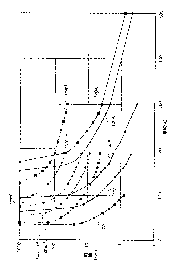
(2)次に、図6にヒュージブルリンク溶断特性及び電線発煙特性を示す。図6において、横軸は、電流値であり、縦軸は、時間である。実線は各定格電流でのヒュージブルリンクの溶断特性を示し、点線は、各電線の発煙特性を示している。各電線は導体断面積(例えば、2mm2、3mm2)で区別している。
【0012】
図6において、ヒュージブルリンクの溶断特性に交わらず、且つ溶断特性の外側に位置する発煙特性を持つ電線の中から電線サイズを決定する。例えば、図11のヒュージブルリンク9e〜9gのように、40Aのヒュージブルリンクを使用した場合には、図6において、40Aのヒュージブルリンクの溶断特性に交わらず、且つ溶断特性の外側に位置する発煙特性を持つ電線の中から電線サイズを決定すると、3mm2となり、3sq電線2h〜2jが決定される。ここで、負荷の要求特性上、電圧降下を考慮して電線サイズを大きく取ることもあるが、通常では、ヒュージブルリンクの溶断特性に近いサイズ(最小サイズ)を使用する。
【0013】
また、一般的にヒュージブルリンクによる保護回路は、下流負荷のロック電流、突入電流は、考慮されていない。ヒュージブルリンクの溶断時間(JASO D614:大電流ヒューズ)は、定格電流の110%で4時間以上、200%で5秒から100秒、350%で0.2秒から7秒、600%で0.04秒から1秒と規定されている。このことは、定格電流の110%では、ヒュージブルリンクが切れないこと、200%で溶断することもあるとも理解でき、溶断性能が曖昧であることを示している。
【0014】
【発明が解決しようとする課題】
しかしながら、図9に示す従来の過電流保護装置114にあっては、ブレードヒューズ103bとPTC素子111とを設けており、回路が複雑でしかも回路が高価なものとなっていた。また、過電流保護装置114は各負荷毎に設けなければならず、複数の過電流保護装置114を収納する収納ケースが大きくなるという問題もあった。
【0015】
また、図11に示す従来のワイヤーハーネス装置にあっては、各負荷、ブロック毎にヒュージブルリンクが設定されているため、ワイヤーハーネス装置が高価になるという問題があった。さらに、図6に示すヒュージブルリンク溶断特性及び電線発煙特性を考慮して、電線サイズが設定されているため、電線サイズが充分余裕をもって大きく設定されている。このため、複数の電線で構成されるワイヤーハーネス全体では、かなりの重量となっていた。
【0016】
本発明は、ヒュージブルリンク等を設けることなく、しかもワイヤーハーネス線径を小径化及び軽量化することにより、安価で簡単な構成からなる過電流保護装置を備えたワイヤーハーネス装置を提供することを課題とする。
【0017】
【課題を解決するための手段】
上記課題を解決するために本発明は、以下の構成とした。請求項1の発明のワイヤーハーネス装置は、電源と負荷との間に設けられ且つ前記電源から電線を構成するワイヤーハーネスを介して前記負荷に流れる過電流を検出して前記電源及び前記負荷間を遮断する過電流保護装置を備えたワイヤーハーネス装置であって、前記過電流保護装置は、前記電源から前記負荷に流れる電流を検出する電流検出手段と、前記電線が完全短絡したときにおける完全短絡電流値をしきい電流値に設定し、前記電流検出手段で検出された電流の値が前記しきい電流値以上になったかどうかを判定する判定手段と、前記電流検出手段で検出された電流の値が前記しきい電流値以上になった場合に前記負荷への前記電源の供給を遮断する遮断装置とを備え、かつこの遮断装置は、前記電源側に接続された第1の接続端子と前記負荷側に接続された第2の接続端子との間に配置され、前記第1の接続端子及び前記第2の接続端子に接触し、加熱剤を充填した導電性を有する加熱部と、この加熱部に収納され、前記電流検出手段で検出された電流の値が前記短絡電流値以上になった場合に前記加熱部に充填された加熱剤に着火する着火部と、前記加熱部に接触して配置され且つ前記加熱部を押圧する伸縮自在な弾性部材と、この弾性部材、前記着火部及び前記加熱部を収納する外容器と、この外容器に形成され且つ前記弾性部材による前記加熱部への押圧力を阻止する樹脂部材からなる突起部と、を備えることを特徴とする。
【0018】
請求項1の発明によれば、電流検出手段が電源から負荷に流れる電流を検出すると、判定手段は、電線が完全短絡したときにおける完全短絡電流値をしきい電流値に設定し、電流検出手段で検出された電流の値がしきい電流値以上になったかどうかを判定し、遮断装置は、電流検出手段で検出された電流の値がしきい電流値以上になった場合に負荷への前記電源の供給を遮断する。
【0019】
このため、過電流保護装置の下流にはヒュージブルリンク等を設けないで済むようになり、簡単で安価なワイヤーハーネス装置を提供でき、また、ヒュージブルリンク等を設けないから、電線径を負荷容量に合わせて最適に選択することができ、これによって、過電流保護装置の下流のワイヤーハーネス線径の小径化及び軽量化を図ることができる。
また、外部からの異常信号により着火部が着火すると、加熱部に充填された加熱剤が発熱し、その熱により外容器に形成された樹脂部材からなる突起部が溶融する。すると、弾性部材が伸張して加熱部を押し上げ、加熱部と第1の接続端子及び第2の接続端子との電気的接続が切断される。このため、第1の接続端子及び第2の接続端子の電気的接続が遮断されるから、回路を短時間で且つ確実に遮断して、電気部品を保護することができる。
【0020】
請求項2の発明の前記しきい電流値は、車両に配索される複数の電線の内の最小径を有する基準長の電線が完全短絡したときにおける電流値であることを特徴とする。
【0021】
請求項2の発明によれば、しきい電流値は、車両に配索される複数の電線の内の最小径を有する基準長の電線が完全短絡したときにおける電流値であるため、より小さい完全短絡電流値により回路を遮断することができる。
【0022】
請求項3の発明の前記判定手段は、前記しきい電流値を前記完全短絡電流値の略30%から略70%までの範囲内の値に設定することを特徴とする。
【0023】
請求項3の発明によれば、判定手段は、しきい電流値を完全短絡電流値の略30%から略70%までの範囲内の値に設定するため、回路をより迅速に遮断することができる。
【0024】
請求項4の発明は、前記過電流保護装置と前記負荷との間にヒューズを設けたことを特徴とする。
【0025】
請求項4の発明によれば、過電流保護装置と負荷との間に設けられたヒューズは、負荷に異常電流が流れたときには溶断するため、回路を遮断することができる。
【0026】
請求項5の発明は、前記電源と第2の負荷との間にヒュージブルリンクを設けたことを特徴とする。
【0027】
請求項5の発明によれば、電源と第2の負荷との間に設けられたヒュージブルリンクは、第2の負荷に異常電流が流れたときには溶断するため、回路を遮断することができ、過電流保護装置の保護を受けない回路に用いることができる。
【0030】
請求項6の発明は、前記加熱部の端部には側壁部が形成され、前記第1の接続端子及び前記第2の接続端子のそれぞれと前記側壁部とを低融点材により接合したことを特徴とする。
【0031】
請求項6の発明によれば、第1の接続端子及び第2の接続端子のそれぞれと側壁部とを低融点材により接合したため、加熱剤の発熱により樹脂部材及び低融点材が溶融すると、加熱部が跳ね上がり、第1の接続端子及び第2の接続端子の電気的接続が遮断されるから、回路を短時間で且つ確実に遮断して、電気部品を保護することができる。また、第1の接続端子及び第2の接続端子と加熱部との接合部である低融点材にバネ力が加わらないため、接合部の信頼性を向上することができる。
【0032】
【発明の実施の形態】
以下、本発明のワイヤーハーネス装置の実施の形態を図面を参照して詳細に説明する。実施の形態のワイヤーハーネス装置は、過電流保護装置を備えて構成される。
【0033】
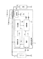
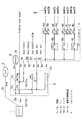
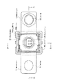
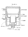
図1は実施の形態の過電流保護装置の回路構成図である。図2は実施の形態の過電流保護装置を備えたワイヤーハーネス装置を示す回路構成図である。図3は実施の形態の過電流保護装置に設けられた遮断装置の遮断前後のA−A間の断面図である。図4は実施の形態の過電流保護装置に設けられた遮断装置の上面図である。図5は実施の形態の過電流保護装置に設けられた遮断装置の遮断前のB−B間の断面図である。
【0034】
まず、実施の形態のワイヤーハーネス装置では、以下の点に着目して、過電流保護装置の下流のワイヤーハーネス線径の小型化、及び軽量化を図った。
【0035】
(1)まず、ヒュージブルリンクの保護範囲は、図6に示す溶断性能からもわかるように、完全短絡(デッドショート)のみカバーしている。完全短絡とは、電線が完全に車体に触れて短絡することである。
【0036】
(2)ヒュージブルリンク溶断性能の余裕が大きいため、図6に示すように、60Aのヒュージブルリンクは、約90A(時間が1000秒における電流値)まで通電可能である。100Aのヒュージブルリンクは、約150A(時間が1000秒における電流値)まで通電可能であり、電線の選定が大きくなりすぎている。
【0037】
(3)(2)より必要以上に電線径が大きくなるため、電線径を抑えるためにヒュージブルリンクの数が多くなる。また、電線径が大きくなると、ワイヤーハーネス製造時、回路のジョイント・端子の取り付け等が制約される。
【0038】
完全短絡時の電流値は、バッテリの充電状態、バッテリの容量・接続電線径によっても違うが、500A以上放電する。この完全短絡時の電流値は、通常使用状態の値とは大きく違うため、判定しやすい。
【0039】
従って、完全短絡時の電流値をしきい電流値として判定して、回路を遮断する過電流保護装置を設定すれば、(a)過電流保護装置の下流にはヒュージブルリンクを必要としない。(b)また、電線径は、負荷容量に合わせた最適径を選択することができる。
【0040】
そこで、以上の点を考慮して図2に示すようなワイヤーハーネス装置を構成した。図2において、バッテリ1には15sq電線2aを介してヒュージブルリンクブロック3が接続され、このヒュージブルリンクブロック3には3sq電線2bを介してリレー4a〜4c及びヒューズ4d〜4kを有するリレー・ヒューズブロック4が接続され、このリレー・ヒューズブロック4には複数の負荷5(5a〜5h)が接続される。
【0041】
ヒュージブルリンクブロック3は、バッテリ1から負荷5,オルタネータ8等の負荷に流れる電流が完全短絡時の電流値となったときにバッテリ1から負荷への電流供給を遮断して回路を保護する過電流保護装置7a,7bと、ヒュージブルリンク9とを備える。
【0042】
また、ヒュージブルリンクブロック3は、2sq電線2e,2sq電線2f,2sq電線2gで構成されるワイヤーハーネスW/Haと、40Aのヒュージブルリンク9を介する3sq電線2hで構成されるワイヤーハーネスW/Hbと、3sq電線2i,3sq電線2j,3sq電線2bで構成されるワイヤーハーネスW/Hcとを備えて構成される。
【0043】
過電流保護装置7aは、15sq電線2aとオルタネータ8に接続された15sq電線2dとの間に設けられ、回路が完全短絡した時にバッテリ1とオルタネータ8との間の回路を遮断して保護する。
【0044】
過電流保護装置7bは、回路が完全短絡したときに回路を遮断して、ワイヤーハーネスW/Haの下流の例えば、パワーウィンドウP/WDW,サンルーフSUN ROOF、ファン(1)(2)等の負荷を保護するとともに、ワイヤーハーネスW/Hcの下流の例えば、ABS UNIT、リレー・ヒューズブロック4を保護する。
【0045】
ここで、過電流保護装置7bは、リレー・ヒューズブロック4よりも右側の回路、すなわち、複数の負荷5a〜5hを保護しない。複数の負荷5a〜5hは、過電流が流れたときにヒューズ4d〜4kの溶断によって保護される。バッテリ1は、20sq電線2cを介してモータ6に電源を供給する。
【0046】
なお、過電流保護装置の保護を受けない回路には、ヒュージブルリンク9を設け、ヒュージブルリンク9を介する3sq電線2hにメーデー回路等の重要な回路を接続している。メーデ回路とは、船舶、航空機が発する無線による救難信号の意味を持ち、この場合には、ハザードランプやホーン、自動車電話等の回路をいう。
【0047】
次に、過電流保護装置7a,7bの構成を図1に従って説明する。ここでは、過電流保護装置7a,7bを過電流保護装置7とした。過電流保護装置7は、図1に示すように、バッテリ1と負荷5との間に設けられており、電源71、電流検出部73、判定回路75、駆動回路77、ヒータ79、及び第1のバスバー11と第2のバスバー19との電気的な接続を遮断する遮断部81を備えて構成される。
【0048】
電源71は、例えば5Vであり、バッテリ1の両端電圧を入力してこの電圧を電流検出部73、判定回路75、及び駆動回路77に供給する。電流検出部73は、バッテリ1から負荷5に流れる電流を検出するもので、例えば、電流センサ等である。電流検出部73は、バッテリ1と負荷5との間に直列にシャント抵抗を介挿入してシャント抵抗の両端電圧を検出してもよい。
【0049】
判定回路75は、電流検出部73で検出された電流の値が予め定められた電流値、例えば、電線が完全短絡したときの完全短絡電流値以上になったかどうかを判定する。駆動回路77は、判定回路75により電流検出部73で検出された電流の値が完全短絡電流値以上になったと判定された場合にヒータ79に電流を流すことにより遮断部81を駆動させる。
【0050】
遮断部81は、ヒータ79の熱により動作して、第1のバスバー11と第2のバスバー19との電気的な接続を遮断して、バッテリ1から負荷5への電源の供給を遮断する。
【0051】
以上の構成によれば、ワイヤーハーネス装置において、1箇所以上の過電流保護装置7a,7bを設け、過電流保護装置7bにおいて、電流検出部73が、バッテリ1から負荷5に流れる電流を検出する。
【0052】
そして、判定回路75が、電流検出部73で検出された電流の値が電線が完全短絡したときの完全短絡電流値以上になったかどうかを判定し、検出された電流の値が完全短絡電流値以上になったと判定された場合にヒータ79に電流が流れて、遮断部81がバッテリ1から負荷5への電源の供給を遮断する。
【0053】
従って、過電流保護装置の下流にはサーキットブレーカやヒュージブルリンク等の保護部材を設けないで済むようになり、簡単で安価なワイヤーハーネス装置を提供することができる。
【0054】
また、ヒュージブルリンク等を設けないから、電線径を負荷容量に合わせて最適に選択することができる。例えば、従来では、図11に示すように60Aのヒュージブルリンクの下流に5sq電線2Bを用いていたが、実施の形態では、図6に示すように、ヒュージブルリンクの溶断特性に関係なく、電線の発煙特性のみを考慮すればよい。
【0055】
電線の発煙特性において、時間が1000秒で約70A(60Aの1.1倍を満たす。)通電可能な電線径である3mm2(3sq電線2b)を選択することができる。すなわち、従来の電線径よりも電線径を小径化できる。従って、過電流保護装置の下流のワイヤーハーネス線径の小径化及び軽量化を図ることができる。さらに、過電流保護装置の収納ケースを簡素化することができる。
【0056】
なお、しきい電流値である完全短絡電流値を、車両に配索される複数の電線の内の最小径を有する基準長の電線が完全短絡したときにおける電流値としてもよい。電線が細いほど、より小さい電流が流れるため、より小さい完全短絡電流値により回路を遮断することができる。
【0057】
基準長は、例えば、1mである。電線の長さにより抵抗値が変化し、この抵抗値の変化により完全短絡電流値も変化する。このため、完全短絡電流値を決定するために電線長を例えば、基準長とした。
【0058】
図2に示すワイヤーハーネス装置では、2sq電線2e,2f,2gが、車両に配索される複数の電線(20sq電線2c、15sq電線2a,2d、3sq電線2b,2h,2i,2j、2sq電線2e,2f,2g等)の内の最小径を有する電線であり、この2sq電線2e,2f,2gが例えば、1m長で完全短絡したときにおける電流値に設定すればよい。
【0059】
また、前述した実施の形態では、しきい電流値を完全短絡電流値としたが、判定回路75が、しきい電流値を完全短絡電流値の略30%から略70%までの範囲内の値に設定してもよい。望ましくは、完全短絡電流値の50%とする。このようにすれば、しきい電流値が完全短絡電流値よりも小さいため、回路をより迅速に遮断することができ、安全性を向上することができる。
【0060】
次に、完全短絡電流値を実際に測定したときにおける試験データを2つ上げて説明する。図7は第1の試料としての電線の完全短絡電流特性を示す図である。図8は第2の試料としての電線の完全短絡電流特性を示す図である。図7及び図8では、電圧の時間的な変化を示している。電圧が急峻に立ち下がったタイミングが電線の完全短絡時である。図7及び図8において、時間軸方向の1目盛は、200msである。
【0061】
(1)まず、第1の試料は、電線径が2mm2(2sq電線)で、電線長が0.5mであり、電線抵抗が4.4mΩである。なお、試験装置取付時には電線抵抗は、r1=4.8mΩであった。完全短絡時の電圧Vaは、3.43Vであった。このため、完全短絡電流値Iaは、
590×0.5=295
となり、約295Aとなる。すなわち、完全短絡電流値の50%をしきい電流値に設定する。
【0062】
(2)次に、第2の試料は、電線径が2mm2(2sq電線)で、電線長が0.5mで、電線抵抗が4.4mΩである。なお、試験装置取付時には電線抵抗は、r1=5.08mΩであった。完全短絡時の電圧Vaは3.77Vであった。このため、完全短絡電流値Iaは、
590×0.5=305
となり、約305Aとなる。すなわち、完全短絡電流値の50%をしきい電流値に設定する。
【0063】
次に、過電流保護装置7に設けられた遮断部81、すなわち、遮断装置について説明する。図3に示す遮断装置において、板状の長い第1のバスバー11は、例えば、銅または銅合金からなり、この第1のバスバー11にはバッテリ等に接続される丸穴部12が形成されている。第1のバスバー11は、下方に略直角に曲げられている。
【0064】
また、板状の長い第2のバスバー19も、例えば、銅または銅合金からなり、この第2のバスバー19には負荷等に接続される丸穴部20が形成されている。第2のバスバー19も下方に略直角に曲げられている。
【0065】
第1のバスバー11と第2のバスバー19との間には上側ケース14aと下側ケース14bとが配置されており、上側ケース14aと下側ケース14bとは、外容器を構成し、樹脂(熱可塑性樹脂)等の絶縁材料の容器からなる。
【0066】
下側ケース14b内には銅、銅合金等からなるテルミットケース26が収納されており、このテルミットケース26には加熱剤27が充填されているとともに、着火部29が収納されている。
【0067】
着火部29は、着火剤を有し、車両の衝突事故等の車両の異常時にリード線51に流れる電流によって発生する発熱により着火剤を点火して加熱剤27にテルミット反応熱を発生させるようになっている。
【0068】
また、テルミットケース26に形成された左側壁部は、第1のバスバー11の折曲部8にハンダ(例えば、融点が200℃〜300℃)等の低融点材としての低融点金属23により接合され、テルミットケース26に形成された右側壁部は、第2のバスバー19の折曲部10に低融点金属23により接合されている。このため、低融点金属23及びテルミットケース26を介して第1のバスバー11と第2のバスバー19とが電気的に接続可能となっている。
【0069】
なお、低融点金属23としては、例えば、Sn、Pb、Zn、Al及びCuから選ばれる少なくとも1種の金属からなる。
【0070】
加熱剤27は、例えば、酸化鉄(Fe2O3)等の金属酸化物の粉末、アルミニウムの粉末とによって構成され、リード線51の発熱によりテルミット反応を起こして高熱を発生するテルミット剤である。なお、酸化鉄(Fe2O3)を用いる代わりに、酸化クロム(Cr2O3)、酸化マンガン(MnO2)などを用いても良い。
【0071】
また、加熱剤27としては、B、Sn、FeSi、Zr、Ti及びAlの中から選ばれる少なくとも1種の金属粉末と、CuO、MnO2、Pb3O4、PbO2、Fe3O4およびFe2O3の中から選ばれる少なくとも1種の金属酸化物と、アルミナ、ベントナイト、タルク等からなる添加剤の少なくとも1種の混合物を用いても良い。このような加熱剤によれば、着火部29により容易に着火され、低融点金属23を短時間で溶融することができる。
【0072】
また、テルミットケース26と下側ケース14bとの間には伸縮自在な弾性部材としての圧縮バネ34が配置されており、この圧縮バネ34がテルミットケース26を上方へ押圧している。
【0073】
また、上側ケース14aには四角形状の溝部37が形成され、この溝部37に、下側ケース14bに形成された第1の突起部39が係合している。下側ケース14bには樹脂部材からなる第2の突起部41が形成されており、この第2の突起部41は、テルミットケース26の上面を押圧し、圧縮バネ34のバネ力によるテルミットケース26の上方への移動を阻止するようになっている。
【0074】
さらに、着火部29にリード線51から電流を供給するためのターミナル50を有するコネクタ45が着火部29に接続可能に取り付けられている。
【0075】
次に、このように構成された実施の形態の遮断装置の動作を図面を参照して説明する。まず、通常では、第1のバスバー11と第2のバスバー19とは、低融点金属23及びテルミットケース26を介して電気的に接続され、バッテリ1から負荷5に電流が供給される。
【0076】
次に、バッテリ1と負荷5との間の回路にが異常が発生して、完全短絡電流が流れたときには、駆動回路77からリード線51を通ってコネクタ45に電圧が印加される。そして、コネクタ45に印加された電圧により着火部29内のヒータ79へ電流が流れる。
【0077】
すると、電流によるヒータ79の発熱により着火部29が発火するため、テルミット剤である加熱剤27が以下の反応式によりテルミット反応熱を発生する。
【0078】
Fe2O3+2AL→AL2O3+2Fe+386.2Kcal
このテルミット反応熱によりテルミットケース26が加熱され、加熱剤27の発熱とテルミットケース26の熱により、折曲部8とテルミットケース26の左側壁部とを接合している低融点金属23、折曲部10とテルミットケース26の右側壁部とを接合している低融点金属23が加熱されて、溶融する。また、これと同時に、下側ケース14bに形成された樹脂部材からなる第2の突起部41が前記熱によって溶融する。
【0079】
すると、圧縮されていた圧縮バネ34が伸張し、着火部29を収納したテルミットケース26が上方に跳ね上がる(図1において、26′は、上方へ移動後のテルミットケースを示す。)。
【0080】
このため、テルミットケース26と、第1のバスバー11及び第2のバスバー19との電気的接続が切断される。すなわち、第1のバスバー11と第2のバスバー19とが電気的に遮断されて、回路が遮断されることになる。
【0081】
このように、実施の形態の遮断装置によれば、車両内のバッテリ1と負荷との間の回路を短時間で且つ確実に遮断することができ、電気部品を保護することができる。さらに、加熱剤27のテルミット反応熱を利用するため、簡単な構造の遮断装置を提供することができる。
【0082】
また、下側ケース14bに形成された第2の突起部41が圧縮バネ34の上方への伸張力を阻止するため、第1のバスバー11及び第2のバスバー19とテルミットケース26との接合部である低融点金属23にバネ力が加わらないため、接合部の信頼性を向上することができる。さらに、接合部が半田等の低融点金属による接合のときには、低融点金属部に応力が加わらないため、クラック発生がなくなる。
【0083】
なお、本発明は、前述した実施の形態のワイヤーハーネス装置に限定されるものではなく、このほか本発明の技術的思想を逸脱しない範囲で種々変形して実施可能であるのは勿論である。
【0084】
【発明の効果】
請求項1の発明によれば、電流検出手段が電源から負荷に流れる電流を検出すると、判定手段は、電線が完全短絡したときにおける完全短絡電流値をしきい電流値に設定し、電流検出手段で検出された電流の値がしきい電流値以上になったかどうかを判定し、遮断装置は、電流検出手段で検出された電流の値がしきい電流値以上になった場合に負荷への前記電源の供給を遮断する。
【0085】
このため、過電流保護装置の下流にはヒュージブルリンク等を設けないで済むようになり、簡単で安価なワイヤーハーネス装置を提供でき、また、ヒュージブルリンク等を設けないから、電線径を負荷容量に合わせて最適に選択することができ、これによって、過電流保護装置の下流のワイヤーハーネス線径の小径化及び軽量化を図ることができる。
また、外部からの異常信号により着火部が着火すると、加熱部に充填された加熱剤が発熱し、その熱により外容器に形成された樹脂部材からなる突起部が溶融する。すると、弾性部材が伸張して加熱部を押し上げ、加熱部と第1の接続端子及び第2の接続端子との電気的接続が切断される。このため、第1の接続端子及び第2の接続端子の電気的接続が遮断されるから、回路を短時間で且つ確実に遮断して、電気部品を保護することができる。
【0086】
請求項2の発明によれば、しきい電流値は、車両に配索される複数の電線の内の最小径を有する基準長の電線が完全短絡したときにおける電流値であるため、より小さい完全短絡電流値により回路を遮断することができる。
【0087】
請求項3の発明によれば、判定手段は、しきい電流値を完全短絡電流値の略30%から略70%までの範囲内の値に設定するため、回路をより迅速に遮断することができる。
【0088】
請求項4の発明によれば、過電流保護装置と負荷との間に設けられたヒューズは、負荷に異常電流が流れたときには溶断するため、回路を遮断することができる。
【0089】
請求項5の発明によれば、電源と第2の負荷との間に設けられたヒュージブルリンクは、第2の負荷に異常電流が流れたときには溶断するため、回路を遮断することができ、過電流保護装置の保護を受けない回路に用いることができる。
【0091】
請求項6の発明によれば、第1の接続端子及び第2の接続端子のそれぞれと側壁部とを低融点材により接合したため、加熱剤の発熱により樹脂部材及び低融点材が溶融すると、加熱部が跳ね上がり、第1の接続端子及び第2の接続端子の電気的接続が遮断されるから、回路を短時間で且つ確実に遮断して、電気部品を保護することができる。また、第1の接続端子及び第2の接続端子と加熱部との接合部である低融点材にバネ力が加わらないため、接合部の信頼性を向上することができる。
【図面の簡単な説明】
【図1】実施の形態の過電流保護装置の回路構成図である。
【図2】実施の形態の過電流保護装置を備えたワイヤーハーネス装置を示す回路構成図である。
【図3】実施の形態の過電流保護装置に設けられた遮断装置の遮断前後のA−A間の断面図である。
【図4】実施の形態の過電流保護装置に設けられた遮断装置の上面図である。
【図5】実施の形態の過電流保護装置に設けられた遮断装置の遮断前のB−B間の断面図である。
【図6】ヒュージブルリンク溶断特性及び電線発煙特性を示す図である。
【図7】第1の試料としての電線の完全短絡電流特性を示す図である。
【図8】第2の試料としての電線の完全短絡電流特性を示す図である。
【図9】従来の過電流保護装置を備えたワイヤーハーネス装置の一例を示す回路図である。
【図10】図9のワイヤーハーネス装置の回路に対応する電流−応答時間特性を示す図である。
【図11】従来のワイヤーハーネス装置の他の一例を示す図である。
【符号の説明】
1 バッテリ
2a〜2j 電線
3 ヒュージブルリンクブロック
4 リレー・ヒューズブロック
4a〜4c リレー
4d〜4k ヒューズ
5 負荷
6 モータ
7,7a,7b 過電流保護装置
8 オールタネータ
9,9a〜9h ヒュージブルリンク
11 第1のバスバー
13,21 バスバー先端部
14a 上側ケース
14b 下側ケース
19 第2のバスバー
23 低融点金属
26 テルミットケース
27 加熱剤
28 ボルト
28a 上蓋
29 着火部
34 圧縮バネ
37 溝部
39 第1の突起部
41 第2の突起部
45 コネクタ
50 ターミナル
51 リード線
71 電源
73 電流検出部
75 判定回路
77 駆動回路
79 ヒータ
81 遮断部[0001]
BACKGROUND OF THE INVENTION
The present invention relates to a wire harness device including an overcurrent protection device that cuts off a circuit when a current from a battery to a load becomes an overcurrent.
[0002]
[Prior art]
In an electrical system installed in a vehicle, when an abnormality occurs in a load such as a power window or when an abnormality occurs in a wire harness composed of a plurality of electric wires connecting the battery and each load, the battery Various protection devices have been developed that melt the fuse inserted between the wire harness and the wire harness to cut off the battery and the wire harness.
[0003]
FIG. 9 is a circuit diagram showing an example of a wire harness device provided with an overcurrent protection device. The wire harness device shown in FIG. 9 includes a circuit that connects a power source (not shown) and the
[0004]
FIG. 10 shows current-response time characteristics corresponding to the circuit of the wire harness device of FIG. In FIG. 10, the
[0005]
As can be seen from FIG. 10, even when the electric wire A having a conductor cross-sectional area smaller than that of the electric wire B is used in the circuit, there is no crossing point on the
[0006]
FIG. 11 shows another example of a conventional wire harness device. In FIG. 11, a
[0007]
The
[0008]
The
[0009]
In the wire harness device described above with reference to FIG. 11, the sizes of the
[0010]
(1) First, a fusible link close to a value obtained by multiplying the sum of downstream loads by a margin ratio (110% to 120%) is selected. For example, when the current of the downstream load is 35 A, 35 A × 1.1 = 38.5 A, so a 40 A fusible link is used.
[0011]
(2) Next, FIG. 6 shows fusible link fusing characteristics and electric wire smoke characteristics. In FIG. 6, the horizontal axis is the current value, and the vertical axis is the time. The solid line shows the fusing characteristics of the fusible link at each rated current, and the dotted line shows the smoke generation characteristics of each electric wire. Each wire has a conductor cross-sectional area (for example, 2 mm23mm2).
[0012]
In FIG. 6, the electric wire size is determined from electric wires having smoke generation characteristics located outside the fusing characteristics, regardless of the fusing characteristics of the fusible link. For example, when a 40A fusible link is used, such as the
[0013]
In general, a protection circuit using a fusible link does not consider the lock current and the inrush current of the downstream load. The fusible link fusing time (JASO D614: high current fuse) is 4 hours or more at 110% of the rated current, 5 to 100 seconds at 200%, 0.2 to 7 seconds at 350%, 0 at 600%. .04 seconds to 1 second. This indicates that at 110% of the rated current, the fusible link cannot be broken, and at 200% it may be blown out, indicating that the fusing performance is ambiguous.
[0014]
[Problems to be solved by the invention]
However, in the conventional
[0015]
Moreover, in the conventional wire harness apparatus shown in FIG. 11, since a fusible link is set for each load and block, there is a problem that the wire harness apparatus becomes expensive. Furthermore, since the wire size is set in consideration of the fusible link fusing property and the wire smoke generation property shown in FIG. 6, the wire size is set large enough with a sufficient margin. For this reason, the entire wire harness composed of a plurality of electric wires has a considerable weight.
[0016]
The present invention provides a wire harness device provided with an overcurrent protection device having an inexpensive and simple configuration by providing a fusible link or the like and reducing the wire harness wire diameter and reducing the weight. Let it be an issue.
[0017]
[Means for Solving the Problems]
In order to solve the above problems, the present invention has the following configuration. The wire harness device of the invention of
[0018]
According to the first aspect of the present invention, when the current detection means detects the current flowing from the power source to the load, the determination means sets the complete short-circuit current value when the wire is completely short-circuited to the threshold current value, and the current detection means Determining whether or not the current value detected at the threshold current value is greater than or equal to the threshold current value, and the interrupting device detects the current to the load when the current detected by the current detection means exceeds the threshold current value. Shut off the power supply.
[0019]
For this reason, it becomes unnecessary to provide a fusible link or the like downstream of the overcurrent protection device, and a simple and inexpensive wire harness device can be provided. It is possible to select optimally according to the capacity, and thereby it is possible to reduce the diameter and weight of the wire harness wire diameter downstream of the overcurrent protection device.
Further, when the ignition part is ignited by an abnormal signal from the outside, the heating agent filled in the heating part generates heat, and the projection made of the resin member formed in the outer container is melted by the heat. Then, the elastic member extends to push up the heating unit, and the electrical connection between the heating unit, the first connection terminal, and the second connection terminal is cut. For this reason, since the electrical connection of the first connection terminal and the second connection terminal is interrupted, the circuit can be reliably interrupted in a short time to protect the electrical components.
[0020]
The threshold current value according to the invention of
[0021]
According to the second aspect of the present invention, the threshold current value is a current value when a reference-length electric wire having a minimum diameter among a plurality of electric wires arranged in a vehicle is completely short-circuited. The circuit can be interrupted by the short-circuit current value.
[0022]
The determination means of the invention of claim 3 is characterized in that the threshold current value is set to a value in a range from approximately 30% to approximately 70% of the complete short-circuit current value.
[0023]
According to the invention of claim 3, since the determination means sets the threshold current value to a value within the range of about 30% to about 70% of the complete short-circuit current value, the circuit can be cut off more quickly. it can.
[0024]
The invention of claim 4 is characterized in that a fuse is provided between the overcurrent protection device and the load.
[0025]
According to the invention of claim 4, since the fuse provided between the overcurrent protection device and the load is blown when an abnormal current flows through the load, the circuit can be interrupted.
[0026]
The invention of
[0027]
According to the invention of
[0030]
Claim6The invention is characterized in that a side wall portion is formed at an end of the heating portion, and each of the first connection terminal and the second connection terminal is joined to the side wall portion by a low melting point material. .
[0031]
Claim6According to the invention, since each of the first connection terminal and the second connection terminal and the side wall portion are joined by the low melting point material, when the resin member and the low melting point material are melted by heat generation of the heating agent, the heating portion jumps up. Since the electrical connection between the first connection terminal and the second connection terminal is cut off, the circuit can be cut off in a short time and reliably to protect the electrical components. In addition, since the spring force is not applied to the low melting point material that is the joint between the first connection terminal and the second connection terminal and the heating portion, the reliability of the joint can be improved.
[0032]
DETAILED DESCRIPTION OF THE INVENTION
Hereinafter, embodiments of a wire harness device of the present invention will be described in detail with reference to the drawings. The wire harness device of the embodiment includes an overcurrent protection device.
[0033]
FIG. 1 is a circuit configuration diagram of an overcurrent protection device according to an embodiment. FIG. 2 is a circuit configuration diagram showing a wire harness device provided with the overcurrent protection device of the embodiment. FIG. 3 is a cross-sectional view taken along line AA before and after the interruption of the interruption device provided in the overcurrent protection device of the embodiment. FIG. 4 is a top view of the interruption device provided in the overcurrent protection device of the embodiment. FIG. 5 is a cross-sectional view taken along the line B-B before the interruption of the interruption device provided in the overcurrent protection device of the embodiment.
[0034]
First, in the wire harness device of the embodiment, focusing on the following points, the wire harness wire diameter downstream of the overcurrent protection device is reduced in size and weight.
[0035]
(1) First, as can be seen from the fusing performance shown in FIG. 6, the protection range of the fusible link covers only a complete short circuit (dead short). A complete short circuit is a short circuit when an electric wire completely touches the vehicle body.
[0036]
(2) Since the margin of fusible link fusing performance is large, as shown in FIG. 6, the fusible link of 60A can be energized up to about 90A (current value at 1000 seconds). The fusible link of 100 A can be energized up to about 150 A (current value at 1000 seconds), and the selection of electric wires is too large.
[0037]
(3) Since the wire diameter becomes larger than necessary than (2), the number of fusible links increases to suppress the wire diameter. In addition, when the wire diameter increases, the attachment of circuit joints and terminals and the like are restricted during the production of the wire harness.
[0038]
The current value at the time of complete short-circuiting is 500 A or more, although it varies depending on the state of charge of the battery, the capacity of the battery and the diameter of the connecting wire. The current value at the time of this complete short circuit is very different from the value in the normal use state, so that it is easy to determine.
[0039]
Therefore, if the current value at the time of complete short-circuit is determined as the threshold current value and an overcurrent protection device that cuts off the circuit is set, (a) no fusible link is required downstream of the overcurrent protection device. (B) Moreover, the electric wire diameter can select the optimal diameter according to the load capacity.
[0040]
In view of the above, a wire harness device as shown in FIG. 2 was constructed. In FIG. 2, a fusible link block 3 is connected to the
[0041]
The fusible link block 3 protects the circuit by cutting off the current supply from the
[0042]
The fusible link block 3 includes a wire harness W / Ha composed of 2sq electric wires 2e, 2sq
[0043]
The
[0044]
The
[0045]
Here, the
[0046]
A
[0047]
Next, the configuration of the
[0048]
The
[0049]
The
[0050]
The shut-off unit 81 operates by the heat of the
[0051]
According to the above configuration, one or more
[0052]
Then, the
[0053]
Therefore, it is not necessary to provide a protective member such as a circuit breaker or a fusible link downstream of the overcurrent protection device, and a simple and inexpensive wire harness device can be provided.
[0054]
In addition, since no fusible link or the like is provided, the wire diameter can be optimally selected according to the load capacity. For example, in the past, as shown in FIG. 11, the 5sq
[0055]
In the smoke generation characteristics of the electric wire, the diameter of the electric wire that can be energized is about 70 A (1.1 times that of 60 A) in 1000 seconds, which is 3 mm.2(3sq
[0056]
Note that the complete short-circuit current value, which is the threshold current value, may be the current value when a reference-length electric wire having the minimum diameter among a plurality of electric wires arranged in the vehicle is completely short-circuited. The thinner the wire, the smaller the current flows, so the circuit can be interrupted with a smaller complete short-circuit current value.
[0057]
The reference length is 1 m, for example. The resistance value changes depending on the length of the electric wire, and the complete short-circuit current value also changes due to the change in the resistance value. For this reason, in order to determine the complete short-circuit current value, the wire length is, for example, the reference length.
[0058]
In the wire harness device shown in FIG. 2, the 2sq
[0059]
In the above-described embodiment, the threshold current value is a complete short-circuit current value. However, the
[0060]
Next, two test data when the complete short-circuit current value is actually measured will be described. FIG. 7 is a diagram showing the complete short-circuit current characteristics of the electric wire as the first sample. FIG. 8 is a diagram showing the complete short-circuit current characteristics of the electric wire as the second sample. 7 and 8 show changes in voltage over time. The timing when the voltage suddenly falls is when the wire is completely short-circuited. 7 and 8, one scale in the time axis direction is 200 ms.
[0061]
(1) First, the first sample has a wire diameter of 2 mm.2(2 sq electric wire), the electric wire length is 0.5 m, and the electric wire resistance is 4.4 mΩ. When the test apparatus was attached, the wire resistance was r1 = 4.8 mΩ. The voltage Va at the time of complete short-circuiting was 3.43V. Therefore, the complete short-circuit current value Ia is
590 × 0.5 = 295
It becomes about 295A. That is, 50% of the complete short-circuit current value is set as the threshold current value.
[0062]
(2) Next, the second sample has a wire diameter of 2 mm.2(2 sq electric wire), the electric wire length is 0.5 m, and the electric wire resistance is 4.4 mΩ. When the test apparatus was attached, the electric wire resistance was r1 = 0.08 mΩ. The voltage Va at the time of complete short-circuiting was 3.77V. Therefore, the complete short-circuit current value Ia is
590 × 0.5 = 305
Becomes about 305A. That is, 50% of the complete short-circuit current value is set as the threshold current value.
[0063]
Next, the interruption | blocking part 81 provided in the
[0064]
The long plate-like second bus bar 19 is also made of, for example, copper or a copper alloy, and the second bus bar 19 is formed with a round hole 20 connected to a load or the like. The second bus bar 19 is also bent downward substantially at a right angle.
[0065]
An upper case 14a and a lower case 14b are arranged between the first bus bar 11 and the second bus bar 19, and the upper case 14a and the lower case 14b constitute an outer container and are made of resin ( It consists of a container of an insulating material such as a thermoplastic resin.
[0066]
A
[0067]
The ignition unit 29 has an igniting agent, and ignites the igniting agent by heat generated by the current flowing through the lead wire 51 when the vehicle is abnormal such as a vehicle collision accident, so that the heating agent 27 generates thermite reaction heat. It has become.
[0068]
Further, the left side wall portion formed in the
[0069]
The low melting point metal 23 is made of, for example, at least one metal selected from Sn, Pb, Zn, Al, and Cu.
[0070]
The heating agent 27 is, for example, iron oxide (Fe2OThree) And the like, and a thermite agent that generates a high heat by causing a thermite reaction by the heat generation of the lead wire 51. Iron oxide (Fe2OThree) Instead of chromium oxide (Cr2OThree), Manganese oxide (MnO2) Etc. may be used.
[0071]
Further, as the heating agent 27, at least one metal powder selected from B, Sn, FeSi, Zr, Ti and Al, CuO, MnO2, PbThreeOFour, PbO2, FeThreeOFourAnd Fe2OThreeA mixture of at least one metal oxide selected from the group consisting of alumina, bentonite, talc and the like may be used. According to such a heating agent, it is easily ignited by the ignition part 29, and the low melting point metal 23 can be melted in a short time.
[0072]
Further, a compression spring 34 as an elastic member that can be expanded and contracted is disposed between the
[0073]
The upper case 14a is formed with a square groove 37, and the first protrusion 39 formed on the lower case 14b is engaged with the groove 37. A
[0074]
Further, a connector 45 having a terminal 50 for supplying current from the lead wire 51 to the ignition unit 29 is attached to the ignition unit 29 so as to be connectable.
[0075]
Next, the operation of the blocking device of the embodiment configured as described above will be described with reference to the drawings. First, normally, the first bus bar 11 and the second bus bar 19 are electrically connected via the low melting point metal 23 and the
[0076]
Next, when an abnormality occurs in the circuit between the
[0077]
Then, since the ignition part 29 is ignited by the heat generation of the
[0078]
Fe2OThree+ 2AL → AL2OThree+ 2Fe + 386.2Kcal
The
[0079]
Then, the compressed compression spring 34 expands, and the
[0080]
For this reason, the electrical connection between the
[0081]
Thus, according to the shut-off device of the embodiment, the circuit between the
[0082]
Further, since the
[0083]
In addition, this invention is not limited to the wire harness apparatus of embodiment mentioned above, Of course, it can implement variously in the range which does not deviate from the technical idea of this invention.
[0084]
【The invention's effect】
According to the first aspect of the present invention, when the current detection means detects the current flowing from the power source to the load, the determination means sets the complete short-circuit current value when the wire is completely short-circuited to the threshold current value, and the current detection means Determining whether or not the current value detected at the threshold current value is greater than or equal to the threshold current value, and the interrupting device detects the current to the load when the current detected by the current detection means exceeds the threshold current value. Shut off the power supply.
[0085]
For this reason, it becomes unnecessary to provide a fusible link or the like downstream of the overcurrent protection device, and a simple and inexpensive wire harness device can be provided. It is possible to select optimally according to the capacity, and thereby it is possible to reduce the diameter and weight of the wire harness wire diameter downstream of the overcurrent protection device.
Further, when the ignition part is ignited by an abnormal signal from the outside, the heating agent filled in the heating part generates heat, and the projection made of the resin member formed in the outer container is melted by the heat. Then, the elastic member extends to push up the heating unit, and the electrical connection between the heating unit, the first connection terminal, and the second connection terminal is cut. For this reason, since the electrical connection of the first connection terminal and the second connection terminal is interrupted, the circuit can be reliably interrupted in a short time to protect the electrical components.
[0086]
According to the second aspect of the present invention, the threshold current value is a current value when a reference-length electric wire having a minimum diameter among a plurality of electric wires arranged in a vehicle is completely short-circuited. The circuit can be interrupted by the short-circuit current value.
[0087]
According to the invention of claim 3, since the determination means sets the threshold current value to a value within the range of about 30% to about 70% of the complete short-circuit current value, the circuit can be cut off more quickly. it can.
[0088]
According to the invention of claim 4, since the fuse provided between the overcurrent protection device and the load is blown when an abnormal current flows through the load, the circuit can be interrupted.
[0089]
According to the invention of
[0091]
Claim6According to the invention, since each of the first connection terminal and the second connection terminal and the side wall portion are joined by the low melting point material, when the resin member and the low melting point material are melted by heat generation of the heating agent, the heating portion jumps up. Since the electrical connection between the first connection terminal and the second connection terminal is cut off, the circuit can be cut off in a short time and reliably to protect the electrical components. In addition, since the spring force is not applied to the low melting point material that is the joint between the first connection terminal and the second connection terminal and the heating portion, the reliability of the joint can be improved.
[Brief description of the drawings]
FIG. 1 is a circuit configuration diagram of an overcurrent protection device according to an embodiment.
FIG. 2 is a circuit configuration diagram illustrating a wire harness device including the overcurrent protection device according to the embodiment.
FIG. 3 is a cross-sectional view taken along line AA before and after the interruption of the interruption device provided in the overcurrent protection device of the embodiment.
FIG. 4 is a top view of the interruption device provided in the overcurrent protection device of the embodiment.
FIG. 5 is a cross-sectional view taken along the line B-B before the interruption of the interruption device provided in the overcurrent protection device of the embodiment.
FIG. 6 is a diagram showing fusible link fusing characteristics and electric wire smoke generation characteristics.
FIG. 7 is a diagram showing a complete short-circuit current characteristic of an electric wire as a first sample.
FIG. 8 is a diagram showing a complete short-circuit current characteristic of an electric wire as a second sample.
FIG. 9 is a circuit diagram showing an example of a wire harness device provided with a conventional overcurrent protection device.
10 is a diagram showing current-response time characteristics corresponding to the circuit of the wire harness device of FIG. 9. FIG.
FIG. 11 is a view showing another example of a conventional wire harness device.
[Explanation of symbols]
1 battery
2a-2j Electric wire
3 fusible link block
4 Relay / fuse block
4a-4c relay
4d-4k fuse
5 Load
6 Motor
7, 7a, 7b Overcurrent protection device
8 Alternator
9, 9a-9h fusible link
11 First bus bar
13,21 Busbar tip
14a Upper case
14b Lower case
19 Second bus bar
23 Low melting point metal
26 Thermit Case
27 Heating agent
28 volts
28a Top lid
29 ignition part
34 Compression spring
37 Groove
39 First protrusion
41 Second protrusion
45 connector
50 terminal
51 Lead wire
71 power supply
73 Current detector
75 judgment circuit
77 Drive circuit
79 Heater
81 Blocking part
Claims (6)
前記過電流保護装置は、
前記電源から前記負荷に流れる電流を検出する電流検出手段と、
前記電線が完全短絡したときにおける完全短絡電流値をしきい電流値に設定し、前記電流検出手段で検出された電流の値が前記しきい電流値以上になったかどうかを判定する判定手段と、
前記電流検出手段で検出された電流の値が前記しきい電流値以上になった場合に前記負荷への前記電源の供給を遮断する遮断装置とを備え、かつ
この遮断装置は、
前記電源側に接続された第1の接続端子と前記負荷側に接続された第2の接続端子との間に配置され、前記第1の接続端子及び前記第2の接続端子に接触し、加熱剤を充填した導電性を有する加熱部と、
この加熱部に収納され、前記電流検出手段で検出された電流の値が前記短絡電流値以上になった場合に前記加熱部に充填された加熱剤に着火する着火部と、
前記加熱部に接触して配置され且つ前記加熱部を押圧する伸縮自在な弾性部材と、
この弾性部材、前記着火部及び前記加熱部を収納する外容器と、
この外容器に形成され且つ前記弾性部材による前記加熱部への押圧力を阻止する樹脂部材からなる突起部と、
を備えることを特徴とするワイヤーハーネス装置。A wire harness provided with an overcurrent protection device provided between a power supply and a load and detecting an overcurrent flowing through the load via a wire harness constituting an electric wire from the power supply and blocking between the power supply and the load A device,
The overcurrent protection device is:
Current detection means for detecting a current flowing from the power source to the load;
A determining means for setting a complete short-circuit current value when the wire is completely short-circuited to a threshold current value, and determining whether or not a current value detected by the current detecting means is equal to or greater than the threshold current value;
A cutoff device that shuts off the supply of the power to the load when the value of the current detected by the current detection means is equal to or greater than the threshold current value ; and
This shut-off device
Arranged between a first connection terminal connected to the power supply side and a second connection terminal connected to the load side, contacting the first connection terminal and the second connection terminal, heating A conductive heating unit filled with an agent;
An ignition part that is housed in this heating part and ignites the heating agent filled in the heating part when the value of the current detected by the current detection means is equal to or greater than the short-circuit current value;
An elastic member which is arranged in contact with the heating unit and which presses the heating unit;
An outer container for housing the elastic member, the ignition part and the heating part;
A protrusion formed of a resin member that is formed in the outer container and prevents pressing force to the heating unit by the elastic member;
A wire harness device comprising:
Priority Applications (2)
| Application Number | Priority Date | Filing Date | Title |
|---|---|---|---|
| JP13171199A JP3654792B2 (en) | 1999-05-12 | 1999-05-12 | Wire harness device |
| DE2000122794 DE10022794A1 (en) | 1999-05-12 | 2000-05-10 | Harness device |
Applications Claiming Priority (1)
| Application Number | Priority Date | Filing Date | Title |
|---|---|---|---|
| JP13171199A JP3654792B2 (en) | 1999-05-12 | 1999-05-12 | Wire harness device |
Publications (2)
| Publication Number | Publication Date |
|---|---|
| JP2000324674A JP2000324674A (en) | 2000-11-24 |
| JP3654792B2 true JP3654792B2 (en) | 2005-06-02 |
Family
ID=15064420
Family Applications (1)
| Application Number | Title | Priority Date | Filing Date |
|---|---|---|---|
| JP13171199A Expired - Fee Related JP3654792B2 (en) | 1999-05-12 | 1999-05-12 | Wire harness device |
Country Status (2)
| Country | Link |
|---|---|
| JP (1) | JP3654792B2 (en) |
| DE (1) | DE10022794A1 (en) |
Families Citing this family (15)
| Publication number | Priority date | Publication date | Assignee | Title |
|---|---|---|---|---|
| ES2269949T3 (en) * | 2003-12-12 | 2007-04-01 | Behr France Rouffach Sas | ELECTRICAL HEATING DEVICE FOR AN AUTOMOBILE VEHICLE. |
| JP4852863B2 (en) * | 2005-03-31 | 2012-01-11 | トヨタ自動車株式会社 | Electric vehicle and protection control method for electric vehicle |
| JP6072514B2 (en) * | 2012-11-14 | 2017-02-01 | 矢崎総業株式会社 | Vehicle battery routing structure |
| JP6252191B2 (en) * | 2014-01-17 | 2017-12-27 | マツダ株式会社 | Vehicle power supply system |
| JP6314845B2 (en) * | 2015-01-08 | 2018-04-25 | 株式会社オートネットワーク技術研究所 | Electrical junction box |
| JP6580364B2 (en) * | 2015-04-27 | 2019-09-25 | 矢崎総業株式会社 | Vehicle electronic unit and power supply control unit |
| US11070049B2 (en) | 2017-11-08 | 2021-07-20 | Eaton Intelligent Power Limited | System, method, and apparatus for power distribution in an electric mobile application using a combined breaker and relay |
| US11368031B2 (en) | 2017-11-08 | 2022-06-21 | Eaton Intelligent Power Limited | Power distribution and circuit protection for a mobile application having a high efficiency inverter |
| WO2019092103A2 (en) | 2017-11-08 | 2019-05-16 | Eaton Intelligent Power Limited | Power distribution unit and fuse management for an electric mobile application |
| US11108225B2 (en) | 2017-11-08 | 2021-08-31 | Eaton Intelligent Power Limited | System, method, and apparatus for power distribution in an electric mobile application using a combined breaker and relay |
| WO2019197459A2 (en) * | 2018-04-10 | 2019-10-17 | Eaton Intelligent Power Limited | System, method, and apparatus for power distribution in an electric mobile application using a combined breaker and relay |
| BE1026371B1 (en) * | 2018-06-13 | 2020-01-23 | Phoenix Contact Gmbh & Co | guard |
| US11689010B2 (en) | 2019-02-22 | 2023-06-27 | Eaton Intelligent Power Limited | Coolant fitting promoting turbulent flow |
| EP4000150B1 (en) | 2019-07-15 | 2025-08-27 | Eaton Intelligent Power Limited | Power distribution and circuit protection for a mobile application having a high efficiency inverter |
| CN113782257B (en) * | 2021-09-08 | 2024-04-05 | 中国科学院理化技术研究所 | Fire-proof cable |
-
1999
- 1999-05-12 JP JP13171199A patent/JP3654792B2/en not_active Expired - Fee Related
-
2000
- 2000-05-10 DE DE2000122794 patent/DE10022794A1/en not_active Ceased
Also Published As
| Publication number | Publication date |
|---|---|
| JP2000324674A (en) | 2000-11-24 |
| DE10022794A1 (en) | 2001-07-05 |
Similar Documents
| Publication | Publication Date | Title |
|---|---|---|
| JP3654792B2 (en) | Wire harness device | |
| US7875997B2 (en) | Circuit interruption device | |
| US6483420B1 (en) | Circuit breaker | |
| US6194988B1 (en) | Low melting point element fusion apparatus and circuit breaker including the same | |
| US11387068B2 (en) | Active/passive fuse module | |
| CN100408382C (en) | Vehicle electrical protection device and system using same | |
| CN108807027B (en) | Externally-driven rapid current cutting device | |
| EP1748459B1 (en) | Electrical protection apparatus | |
| US20040041682A1 (en) | Battery circuit disconnect device | |
| US6243245B1 (en) | Forced-fusion fuse and circuit breaker | |
| JP2001520436A (en) | Circuit device and method for operating a fuse element | |
| JP2020527930A (en) | Integrated switching equipment, and battery monitoring and protection systems including integrated switching equipment | |
| CN114336879A (en) | Battery circuit, battery management system, battery module and electric automobile | |
| US9490094B2 (en) | Overcurrent protection apparatus | |
| JP2000260277A (en) | Circuit breaker | |
| US20210350994A1 (en) | Active/passive fuse module | |
| JP2000215769A (en) | Circuit breaker | |
| JP7181295B2 (en) | Electrochemical energy storage modules and vehicles | |
| CN220873514U (en) | Fuse for accelerating medium-multiplying power overcurrent fusing speed | |
| JP2001045648A (en) | Circuit breaker | |
| WO2025044389A1 (en) | Fuse having higher medium-rate overcurrent fusing speed | |
| CN105305370A (en) | Electric automobile short circuit protector | |
| KR102926328B1 (en) | DC electrical circuit breaker switch assembly | |
| GB2077500A (en) | Thermal fuse | |
| JP2001025150A (en) | Circuit breaker |
Legal Events
| Date | Code | Title | Description |
|---|---|---|---|
| A131 | Notification of reasons for refusal |
Free format text: JAPANESE INTERMEDIATE CODE: A131 Effective date: 20040302 |
|
| A521 | Written amendment |
Free format text: JAPANESE INTERMEDIATE CODE: A523 Effective date: 20040506 |
|
| TRDD | Decision of grant or rejection written | ||
| A01 | Written decision to grant a patent or to grant a registration (utility model) |
Free format text: JAPANESE INTERMEDIATE CODE: A01 Effective date: 20050222 |
|
| A61 | First payment of annual fees (during grant procedure) |
Free format text: JAPANESE INTERMEDIATE CODE: A61 Effective date: 20050301 |
|
| R150 | Certificate of patent (=grant) or registration of utility model |
Free format text: JAPANESE INTERMEDIATE CODE: R150 |
|
| LAPS | Cancellation because of no payment of annual fees |