JP3652602B2 - Arc tube and manufacturing method thereof - Google Patents
Arc tube and manufacturing method thereof Download PDFInfo
- Publication number
- JP3652602B2 JP3652602B2 JP2000370610A JP2000370610A JP3652602B2 JP 3652602 B2 JP3652602 B2 JP 3652602B2 JP 2000370610 A JP2000370610 A JP 2000370610A JP 2000370610 A JP2000370610 A JP 2000370610A JP 3652602 B2 JP3652602 B2 JP 3652602B2
- Authority
- JP
- Japan
- Prior art keywords
- arc tube
- pinch seal
- discharge space
- pair
- neck
- Prior art date
- Legal status (The legal status is an assumption and is not a legal conclusion. Google has not performed a legal analysis and makes no representation as to the accuracy of the status listed.)
- Expired - Fee Related
Links
Images


Classifications
-
- H—ELECTRICITY
- H01—ELECTRIC ELEMENTS
- H01J—ELECTRIC DISCHARGE TUBES OR DISCHARGE LAMPS
- H01J61/00—Gas-discharge or vapour-discharge lamps
- H01J61/02—Details
- H01J61/36—Seals between parts of vessels; Seals for leading-in conductors; Leading-in conductors
- H01J61/366—Seals for leading-in conductors
- H01J61/368—Pinched seals or analogous seals
-
- H—ELECTRICITY
- H01—ELECTRIC ELEMENTS
- H01J—ELECTRIC DISCHARGE TUBES OR DISCHARGE LAMPS
- H01J9/00—Apparatus or processes specially adapted for the manufacture, installation, removal, maintenance of electric discharge tubes, discharge lamps, or parts thereof; Recovery of material from discharge tubes or lamps
- H01J9/24—Manufacture or joining of vessels, leading-in conductors or bases
- H01J9/32—Sealing leading-in conductors
- H01J9/323—Sealing leading-in conductors into a discharge lamp or a gas-filled discharge device
- H01J9/326—Sealing leading-in conductors into a discharge lamp or a gas-filled discharge device making pinched-stem or analogous seals
Landscapes
- Engineering & Computer Science (AREA)
- Manufacturing & Machinery (AREA)
- Vessels And Coating Films For Discharge Lamps (AREA)
- Manufacture Of Electron Tubes, Discharge Lamp Vessels, Lead-In Wires, And The Like (AREA)
Description
【0001】
【発明の属する技術分野】
本願発明は、車両用前照灯の光源として用いられるアークチューブに関するものである。
【0002】
【従来の技術】
アークチューブは高輝度照射が可能なことから、近年では車両用前照灯等の光源としても多く用いられるようになってきている。
【0003】
車両用前照灯等に用いられるアークチューブは、一般に、図12に示すように、放電空間102を形成する発光管部104aの両側に各々ピンチシール部104bが形成されてなる石英ガラス製のアークチューブ本体104と、タングステン電極108およびリード線110がモリブデン箔112を介して連結固定されてなる1対の電極アッシー106とからなり、各電極アッシー106は、そのタングステン電極108の先端部を放電空間102へ突出させるようにして、各ピンチシール部104bにおいてアークチューブ本体104にピンチシールされている。そして、このアークチューブの放電空間102には、点灯時の演色性を高めるため、不活性ガスおよび水銀に加えて金属ハロゲン化物が封入されている。
【0004】
【発明が解決しようとする課題】
上記アークチューブ本体104は、石英ガラス管に熱加工を施すことにより形成されているので、放電空間102の軸線方向両端部における各タングステン電極108の周囲には、略楔状のスリット102aが不可避的に形成されることとなる。これら各スリット102aは、アークチューブの点灯時における温度が放電空間102の他の部位に比して低いので、該スリット102aには金属ハロゲン化物が堆積しやすい。そして、同図に示すように、各スリット102aに堆積した金属ハロゲン化物114はアークチューブの点灯時の発光に寄与しないので、アークチューブの発光色が所期の色とは異なった色に変化してしまうという問題がある。また、各スリット102aへの金属ハロゲン化物114の堆積量がある程度以上になると、アークチューブの点灯に有効利用可能な金属ハロゲン化物が不足するため、点灯不良を引き起こしてしまうという問題もある。
【0005】
本願発明はこのような事情に鑑みてなされたものであって、スリットへの金属ハロゲン化物の堆積による発光色の変化や点灯不良の発生を効果的に抑制することができるアークチューブおよびその製造方法を提供することを目的とするものである。
【0006】
【課題を解決するための手段】
本願発明は、アークチューブ本体の構成に工夫を施すことにより、スリットの容積を縮小させて金属ハロゲン化物の堆積量の削減を図るようにし、もって上記目的達成を図るようにしたものである。
【0007】
すなわち、本願発明に係るアークチューブは、
車両用前照灯の光源として用いられるアークチューブであって、
放電空間を形成する発光管部の両側に各々ピンチシール部が形成されるとともに、上記発光管部と上記各ピンチシール部との間に各々左右1対のネック部が形成されてなる石英ガラス製のアークチューブ本体と、上記放電空間へ先端部を突出させるようにして上記各ピンチシール部において上記アークチューブ本体にピンチシールされた1対のタングステン電極とを備え、上記放電空間の軸線方向両端部におけるタングステン電極の左右両側に、上記ネック部よりも上記発光管部から離れた位置まで延びる略楔状のスリットが形成されてなるアークチューブにおいて、
上記ピンチシール部の、互いに対向する1対のピンチシール面の各々が、一般部とこの一般部に対して段下がりで略平面状に形成された段下がり平面部とからなり、
上記ネック部から上記ピンチシール部における各ピンチシール面の段下がり平面部までの軸線方向距離が、いずれも1mm以下の値に設定されている、ことを特徴とするものである。
【0009】
また、本願発明に係るアークチューブの製造方法は、
車両用前照灯の光源として用いられるアークチューブの製造方法であって、
放電空間を形成する発光管部の両側に各々ピンチシール部が形成されるとともに、上記発光管部と上記各ピンチシール部との間に各々左右1対のネック部が形成されてなる石英ガラス製のアークチューブ本体と、上記放電空間へ先端部を突出させるようにして上記各ピンチシール部において上記アークチューブ本体にピンチシールされた1対のタングステン電極とを備え、上記放電空間の軸線方向両端部におけるタングステン電極の左右両側に、上記ネック部よりも上記発光管部から離れた位置まで延びる略楔状のスリットが形成されてなるアークチューブを製造する方法において、
上記ピンチシールを、上記ピンチシール部に段下がり平面部を形成するための段上がり平面部を有する1対のピンチャを用い、これら各ピンチャの段上がり平面部における上記発光管部側の端縁を上記ネック部の形成予定位置から1mm以下の軸線方向距離の位置で上記アークチューブ本体に当接させるようにして行う、ことを特徴とするものである。
【0010】
上記「タングステン電極」は、タングステンを主成分とするものであれば、純粋なタングステン製の電極であってもよいし、その他の成分が添加された電極であってもよい。
【0011】
上記「軸線方向距離」とは、アークチューブの軸線方向に沿った距離を意味する物である。
【0012】
上記「ネック部」は、発光管部とピンチシール部との間のくびれた部分を意味するものであり、そのアークチューブの軸線方向の位置は最もくびれた位置として特定される。
【0013】
上記「段下がり平面部」は、一般部に対して段下がりで略平面状に形成されたものであれば、その輪郭形状や一般部に対する段下がり量等の具体的構成は特に限定されるものではない。
【0014】
本願各発明における「軸線方向距離」の範囲設定は、発光管部の両側のピンチシール部の双方に適用されるものであってもよいし、そのいずれか一方にのみ適用されるものであってもよい。
【0015】
【発明の作用効果】
上記構成に示すように、本願発明に係るアークチューブは、そのアークチューブ本体に形成されたピンチシール部の、互いに対向する1対のピンチシール面の各々が、一般部とこの一般部に対して段下がりで略平面状に形成された段下がり平面部とからなり、ネック部からピンチシール部における各ピンチシール面の段下がり平面部までの軸線方向距離が、いずれも1mm以下の値に設定されているので、次のような作用効果を得ることができる。
【0016】
すなわち、ネック部からピンチシール部における各ピンチシール面の段下がり平面部までの軸線方向距離が非常に短いので、ピンチシールの際、タングステン電極に対してその先端部寄りの部位まで十分なピンチング圧力を作用させることができる。そしてこれにより放電空間の軸線方向両端部に形成される略楔状のスリットの容積を縮小させることができるので、該スリットへの金属ハロゲン化物の堆積量削減を図ることができ、これによりアークチューブの発光色の変化や点灯不良の発生を効果的に抑制することができる。
【0019】
また、本願発明に係るアークチューブの製造方法は、アークチューブ本体のピンチシール部においてタングステン電極をピンチシールする際、該ピンチシール部に段下がり平面部を形成するための段上がり平面部を有する1対のピンチャを用い、これら各ピンチャの段上がり平面部における発光管部側の端縁をネック部の形成予定位置から1mm以下の軸線方向距離の位置でアークチューブ本体に当接させるようにしてピンチシールを行うようになっているので、次のような作用効果を得ることができる。
【0020】
すなわち、ピンチシールの際、ピンチャの段上がり平面部における発光管部側の端縁がネック部の形成予定位置から極めて近い位置でアークチューブ本体に当接するので、タングステン電極に対してその先端部寄りの部位まで十分なピンチング圧力を作用させることができる。そしてこれにより放電空間の軸線方向両端部に形成される略楔状のスリットの容積を縮小させることができるので、該スリットへの金属ハロゲン化物の堆積量削減を図ることができ、これによりアークチューブの発光色の変化や点灯不良の発生を効果的に抑制することができる。
【0021】
【発明の実施の形態】
以下、図面を用いて、本願発明の実施の形態について説明する。
【0022】
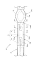
図1は、本願発明の一実施形態に係るアークチューブが組み込まれた放電バルブ10を示す側断面図であり、図2は、そのII部拡大図である。また、図3は、図2のIII-III 線断面図である。
【0023】
これらの図に示すように、この放電バルブ10は車両用前照灯に装着される光源バルブであって、前後方向に延びるアークチューブユニット12と、このアークチューブユニット12の後端部を固定支持する絶縁プラグユニット14とを備えてなっている。
【0024】
アークチューブユニット12は、アークチューブ16と、このアークチューブ16を囲むシュラウドチューブ18とが一体的に形成されてなっている。
【0025】
アークチューブ16は、石英ガラス管を加工してなるアークチューブ本体20と、このアークチューブ本体20内に埋設された前後1対の電極アッシー22とからなっている。
【0026】
アークチューブ本体20は、中央に略楕円球状の発光管部20Aが形成されるとともにその前後両側にピンチシール部20Bが形成されてなっている。発光管部20Aの内部には前後方向に延びる略楕円球状の放電空間24が形成されており、この放電空間24には水銀とキセノンガスと金属ハロゲン化物(例えば金属ヨウ化物)とが封入されている。
【0027】
各電極アッシー22は、棒状のタングステン電極26とリード線28とがモリブデン箔30を介して各々溶接により連結固定されてなり、各ピンチシール部20Bにおいてアークチューブ本体20にピンチシールされている。その際、各タングステン電極26は、その先端部が前後両側から互いに対向するようにして放電空間24内に突出した状態で、その先端部以外の部分がピンチシール部20B内に埋設されており、各モリブデン箔30は、その全体がピンチシール部20B内に埋設されている。
【0028】
図4は、図2のIV-IV 方向矢視図であり、図5および6は、図4のV-V 線断面図およびVI-VI 線断面図である。
【0029】
これらの図に示すように、前方側のピンチシール部20Bは、平面視において発光管部20Aから前方へ延びる略矩形形状を有しており、モリブデン箔30よりもある程度大きいサイズで形成されている。そして、このピンチシール部20Bと発光管部20Aとの間には、左右1対のネック部20Cが形成されている。なお、後方側のピンチシール部20Bについてもこれと同様の構成であるので、以下、前方側のピンチシール部20Bについて説明する。
【0030】
ピンチシール部20Bは、その断面形状が略横長矩形形状に設定されており、その上下両面20Baは、いずれも一般部20Ba1と段下がり平面部20Ba2とからなっている。
【0031】
一般部20Ba1は、上下各面20Baにおける左右両端部領域および後端部領域と、モリブデン箔30とタングステン電極26との接合部を含むようにして前後方向に延びるU字形領域と、モリブデン箔30とリード線28との接合部を含むようにして前後方向に延びる長円形領域とからなり、これら各領域が同一平面上に位置するようにして形成されている。一方、段下がり平面部20Ba2は、一般部20Ba1以外の全領域であって、一般部20Ba1に対して段下がりで平面状に形成されている。
【0032】
ピンチシール部20Bは、その幅AがA=3.8〜4.6mmに設定されており、その厚さBがB=1.8〜2.2mmに設定されている。ここで、幅Aは、左右方向の幅寸法であり、厚さBは、上下両面20Baの段下がり平面部20Ba2相互間の上下寸法である。
【0033】
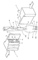
図7および8は、前方側のピンチシール部20Bを形成するピンチシール工程を示す斜視図および平断面図である。
【0034】
これらの図に示すように、このピンチシール工程においては、すでに後方側のピンチシール部20Bが形成されたアークチューブ本体20を、その前端部が上を向くように配置した状態で、その発光管部20Aの上方に位置するピンチシール予定部20B´に対して1対のピンチャ2を左右両側から押し当てることにより、ピンチシール部20Bを形成するようになっている。
【0035】
両ピンチャ2は、平面視において点対称構造となっている。そして各ピンチャ2は、ピンチシール部20Bの上下各面20Baを形成するための正面部2aと、ピンチシール部20Bの両側面を形成するための側面部2bと、ピンチシールの際に相手側ピンチャに当接するストッパ部2cと、相手側ピンチャのストッパ部2cを受けるストッパ受け部2dとが形成されてなっている。各ピンチャ2の正面部2aには、ピンチシール部20Bの上下各面20Baにおける一般部20Ba1および段下がり平面部20Ba2に対応する一般部2a1および段上がり平面部2a2が形成されている。そして両ピンチャ2のストッパ部2cとストッパ受け部2dとの当接によりピンチシール時の成形空間が形成されるが、このとき両ピンチャ2の正面部2aの段上がり平面部2a2相互間の間隔D(B)によってピンチシール部20Bの厚さBが決定される。
【0036】
ところで、ピンチシール部20Bの上下各面20Baに、その一般部20Ba1としてU字形領域および長円形領域が設定されているのは、モリブデン箔30とタングステン電極26およびリード線28との各接合部において石英ガラスの肉厚が薄くなり割れが発生するのを未然に防止するためである。なお、これらU字形領域および長円形領域を一般部20Ba1として設定しておくことにより、電極アッシー22(特にタングステン電極26の先端部)の向きが前後方向軸線に対して左右方向に大きくずれないようにすることができる。
【0037】
ピンチシール予定部20B´は、アークチューブ本体20における一般の管状中空部に比して小径の中実構造となっており、その内部に電極アッシー22が位置決めされた状態で埋設されている。このピンチシール予定部20B´は、図9に示すように、ピンチシール工程の前工程であるシュリンクシール工程において、電極アッシー22が挿入されたアークチューブ本体20を左右両側から1対のバーナ4で加熱して該アークチューブ本体20を所定長にわたって熱収縮させることにより形成されるようになっている。
【0038】
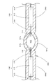
図3および4に示すように、上記ピンチシールにより形成されたアークチューブ本体20には、その放電空間24の軸線方向両端部におけるタングステン電極26の左右両側に略楔状のスリット24aが形成される。一方、図2に示すように、放電空間24の軸線方向両端部におけるタングステン電極26の上下両側には、ピンチシール時にピンチャ2の押圧力が直接作用するため、このようなスリット24aはほとんど形成されない。
【0039】
図10は、図3の要部詳細図である。
【0040】
同図において、ネック部20Cからピンチシール部20Bにおける各ピンチシール面20Baの段下がり平面部20Ba2までの軸線方向距離L1は、いずれも1mm(より好ましくは0.75mm)以下の値(例えばL1=0.5〜0.7mm程度)に設定されている。これを実現するため、上記ピンチシール工程においては、各ピンチャ2の正面部2aにおける段上がり平面部2a2の下端縁がネック部20Cの形成予定位置から上方1mm以下の位置でアークチューブ本体20に当接させることによりピンチシールを行うようになっている。
【0041】
このようにネック部20Cからピンチシール部20Bにおける各ピンチシール面20Baの段下がり平面部20Ba2までの軸線方向距離L1を非常に短い値に設定することにより、ピンチシールの際、タングステン電極26に対してその先端部寄りの部位まで十分なピンチング圧力を作用させることができる。その結果、図10に示すように、タングステン電極26の左右両側に形成されるスリット24aは、いずれもその先端がネック部20Cよりも前方(発光管部20Aから離れる側)まで延びているが、ネック部20Cからスリット24aの先端までの軸線方向距離L2は0.5mm(より好ましくは0.25mm)以下の値(例えばL2=0.1〜0.2mm)となっている。そしてこれによりスリット24aの容積を縮小させることができるので、該スリット24aへの金属ハロゲン化物の堆積量削減を図ることができ、これによりアークチューブ16の発光色の変化や点灯不良の発生を効果的に抑制することができる。
【0042】
なお、従来のアークチューブにおいては、ネック部20Cからピンチシール部20Bにおける各ピンチシール面20Baの段下がり平面部20Ba2までの軸線方向距離L1はL1=1.5〜2.5mm程度であり、その結果、ネック部20Cからスリット24aの先端まで軸線方向距離L2はL2=0.75〜2.0mm程度となっている。
【0043】
図11は、本実施形態に係るアークチューブ16の性能を確認するために行った実験の結果を示す色度図である。
【0044】
この実験は、アークチューブを連続点灯させたときの発光色の変化を調べるために、その色度を経時的に測定した実験である。供試サンプルは、スリット無しのアークチューブ(L2<0.25mmのもの)とスリットありのアークチューブ(L2>0.75mmのもの)とを各々10個ずつ準備した。そして、色度測定は、点灯を開始してから0時間、500時間、1000時間、1500時間の各時点で行った。
【0045】
同図において、(a)がスリット無しのアークチューブの実験結果であり、(b)がスリットありのアークチューブの実験結果である。図中の「+」印は10個のサンプルの平均値である。また、同図において矩形枠で示す色度範囲(0.360<x<0.410、0.375<y<0.405)が、車両用前照灯に装着される光源バルブ用のアークチューブとして好ましい色度範囲である。
【0046】
実験の結果は、図示のように、点灯開始直後は、スリット無しのアークチューブもスリットありのアークチューブも略同じ色度であったが、点灯時間が長くなると、スリットありのアークチューブは、スリット無しのアークチューブに比して色度が大きく変化した。そして、スリットありのアークチューブの色度は、点灯開始後1000時間で略すべてのサンプルが上記矩形枠の左下に外れてしまった。
【0047】
このようにスリットありのアークチューブの色度が大きく変化したのは、スリットへの金属ハロゲン化物の堆積によるものであると考察されるが、このような色度変化があると、アークチューブの発光色は青白くなりすぎてしまう。この点、スリット無しのアークチューブの色度はさほど変化しておらず、アークチューブの発光色が青白くなりすぎてしまうことはない。
【0048】
以上詳述したように、本実施形態に係るアークチューブ16は、ネック部20Cからピンチシール部20Bにおける各ピンチシール面20Baの段下がり平面部20Ba2までの軸線方向距離L1が1mm以下の値に設定されているので、ピンチシールの際、タングステン電極26に対してその先端部寄りの部位まで十分なピンチング圧力を作用させることができる。その結果、ネック部20Cからタングステン電極26の左右両側に形成されるスリット24aの先端までの軸線方向距離L2を0.5mm以下の値とすることができる。そしてこれによりスリット24aの容積を縮小させることができるので、該スリット24aへの金属ハロゲン化物の堆積量削減を図ることができる。
【0049】
したがって本実施形態によれば、アークチューブ16の発光色の変化や点灯不良の発生を効果的に抑制することができる。
【0050】
本実施形態においては、車両用前照灯に装着される放電バルブ10のアークチューブ16について説明したが、これ以外の用途に用いられるアークチューブにおいても、本実施形態と同様の構成を採用することにより本実施形態と同様の作用効果を得ることが可能である。
【図面の簡単な説明】
【図1】本願発明の一実施形態に係るアークチューブが組み込まれた放電バルブを示す側断面図
【図2】図1のII部拡大図
【図3】図2のIII-III 線断面図
【図4】図2のIV方向矢視図
【図5】図4のV-V 線断面図
【図6】図4のVI-VI 線断面図
【図7】上記アークチューブにおける前方側のピンチシール部を形成するピンチシール工程を示す斜視図
【図8】上記ピンチシール工程を示す平断面図
【図9】上記ピンチシール工程の前工程であるシュリンクシール工程を示す平断面図
【図10】図3の要部詳細図
【図11】上記実施形態に係るアークチューブの性能を確認するために行った実験の結果を示す色度図
【図12】従来例を示す、図3と同様の図
【符号の説明】
2 ピンチャ
2a 正面部
2a1 一般部
2a2 段上がり平面部
2b 側面部
2c ストッパ部
2d ストッパ受け部
4 バーナ
10 放電バルブ
12 アークチューブユニット
14 絶縁プラグユニット
16 アークチューブ
18 シュラウドチューブ
20 アークチューブ本体
20A 発光管部
20B ピンチシール部
20Ba 上面、下面
20Ba1 一般部
20Ba2 段下がり平面部
20B´ ピンチシール予定部
20C ネック部
22 電極26アッシー
24 放電空間
24a スリット
26 タングステン電極
28 リード線
30 モリブデン箔
L1 ネック部からピンチシール部における各ピンチシール面の段下がり平面部までの軸線方向距離
L2 ネック部からスリットの先端まで軸線方向距離[0001]
BACKGROUND OF THE INVENTION
The present invention relates to an arc tube used as a light source of a vehicle headlamp.
[0002]
[Prior art]
Since arc tubes are capable of high-intensity irradiation, in recent years, they are often used as light sources for vehicle headlamps and the like.
[0003]
As shown in FIG. 12, an arc tube used for a vehicle headlamp or the like is generally a quartz glass arc in which
[0004]
[Problems to be solved by the invention]
Since the
[0005]
The present invention has been made in view of such circumstances, and an arc tube capable of effectively suppressing the change in emission color and the occurrence of lighting failure due to the deposition of metal halide in the slit, and a method for manufacturing the arc tube Is intended to provide.
[0006]
[Means for Solving the Problems]
According to the present invention, the configuration of the arc tube main body is devised to reduce the volume of the metal halide by reducing the volume of the slit, thereby achieving the above object.
[0007]
That is, the arc tube according to the present invention is
An arc tube used as a light source for a vehicle headlamp,
Made of quartz glass in which pinch seal portions are formed on both sides of the arc tube portion forming the discharge space, and a pair of left and right neck portions are formed between the arc tube portion and the pinch seal portions, respectively. And a pair of tungsten electrodes pinched and sealed to the arc tube main body at each pinch seal portion so that the tip portion protrudes into the discharge space, and both end portions in the axial direction of the discharge space In the arc tube in which a substantially wedge-shaped slit extending to a position farther from the arc tube part than the neck part is formed on both the left and right sides of the tungsten electrode in
Each of the pair of pinch seal surfaces facing each other of the pinch seal part is composed of a general part and a stepped flat part formed in a substantially flat shape with a step down with respect to the general part,
The axial distance from the neck portion to the stepped flat surface portion of each pinch seal surface in the pinch seal portion is set to a value of 1 mm or less.
[0009]
The manufacturing method of the arc tube according to the present invention is as follows:
A method of manufacturing an arc tube used as a light source for a vehicle headlamp,
Made of quartz glass in which pinch seal portions are formed on both sides of the arc tube portion forming the discharge space, and a pair of left and right neck portions are formed between the arc tube portion and the pinch seal portions, respectively. And a pair of tungsten electrodes pinched and sealed to the arc tube main body at each pinch seal portion so that the tip portion protrudes into the discharge space, and both end portions in the axial direction of the discharge space In the method of manufacturing an arc tube in which a substantially wedge-shaped slit extending to a position farther from the arc tube portion than the neck portion is formed on both the left and right sides of the tungsten electrode in
The pinch seal is formed by using a pair of pinchers having a step-up flat portion for forming a step-down flat portion on the pinch seal portion, and an edge on the arc tube portion side in the step-up flat portion of each pincher is defined. The arc tube main body is brought into contact with the arc tube main body at a position of an axial distance of 1 mm or less from a planned formation position of the neck portion.
[0010]
The “tungsten electrode” may be a pure tungsten electrode or an electrode to which other components are added, as long as it contains tungsten as a main component.
[0011]
The “axial distance” means a distance along the axial direction of the arc tube.
[0012]
The “neck portion” means a constricted portion between the arc tube portion and the pinch seal portion, and the position of the arc tube in the axial direction is specified as the most constricted position.
[0013]
The above-mentioned “step-down plane part” is not particularly limited as long as it is formed in a substantially flat shape with a step-down with respect to the general part, such as its contour shape and the step-down amount with respect to the general part. is not.
[0014]
The range setting of “axial distance” in each invention of the present application may be applied to both of the pinch seal portions on both sides of the arc tube portion, or may be applied to only one of them. Also good.
[0015]
[Effects of the invention]
As shown in the above configuration, in the arc tube according to the present invention, each of the pair of pinch seal surfaces facing each other of the pinch seal portion formed in the arc tube main body has a general portion and the general portion. It consists of a stepped flat portion formed in a substantially flat shape by stepping, and the axial distance from the neck portion to the stepped flat portion of each pinch seal surface in the pinch seal portion is set to a value of 1 mm or less. Therefore, the following effects can be obtained.
[0016]
That is, since the axial distance from the neck portion to the stepped flat surface portion of each pinch seal surface in the pinch seal portion is very short, sufficient pinching pressure to the portion closer to the tip portion with respect to the tungsten electrode at the time of pinch seal Can act. As a result, the volume of the substantially wedge-shaped slits formed at both ends in the axial direction of the discharge space can be reduced, so that the amount of metal halide deposited on the slits can be reduced. It is possible to effectively suppress the change in emission color and the occurrence of lighting failure.
[0019]
In addition, the arc tube manufacturing method according to the present invention has a step-up flat portion for forming a step-down flat portion in the pinch seal portion when pinching the tungsten electrode in the pinch seal portion of the arc tube main body. Using a pair of pinchers, pinches are made such that the edge on the arc tube side of the raised flat part of each pincher is brought into contact with the arc tube body at an axial distance of 1 mm or less from the position where the neck part is to be formed. Since sealing is performed, the following operational effects can be obtained.
[0020]
That is, at the time of pinch sealing, the edge on the arc tube portion side of the raised flat portion of the pincher abuts the arc tube body at a position very close to the position where the neck portion is to be formed. Sufficient pinching pressure can be applied to this part. As a result, the volume of the substantially wedge-shaped slits formed at both ends in the axial direction of the discharge space can be reduced, so that the amount of metal halide deposited on the slits can be reduced. It is possible to effectively suppress the change in emission color and the occurrence of lighting failure.
[0021]
DETAILED DESCRIPTION OF THE INVENTION
Hereinafter, embodiments of the present invention will be described with reference to the drawings.
[0022]
FIG. 1 is a side sectional view showing a
[0023]
As shown in these drawings, the
[0024]
In the
[0025]
The
[0026]
The arc tube
[0027]
Each
[0028]
4 is a view taken in the direction of arrows IV-IV in FIG. 2, and FIGS. 5 and 6 are cross-sectional views taken along lines VV and VI-VI in FIG.
[0029]
As shown in these drawings, the front-side
[0030]
The
[0031]
The general portion 20Ba1 includes left and right end regions and rear end regions on each of the upper and lower surfaces 20Ba, a U-shaped region extending in the front-rear direction so as to include a joint between the
[0032]
The
[0033]
7 and 8 are a perspective view and a plan sectional view showing a pinch seal process for forming the front side
[0034]
As shown in these drawings, in this pinch sealing process, the
[0035]
Both
[0036]
By the way, the U-shaped region and the oval region are set as the general portion 20Ba1 on the upper and lower surfaces 20Ba of the
[0037]
The pinch seal planned
[0038]
As shown in FIGS. 3 and 4, the
[0039]
FIG. 10 is a detailed view of a main part of FIG.
[0040]
In the figure, the axial distance L1 from the
[0041]
In this way, by setting the axial distance L1 from the
[0042]
In the conventional arc tube, the axial distance L1 from the
[0043]
FIG. 11 is a chromaticity diagram showing the results of an experiment conducted for confirming the performance of the
[0044]
This experiment is an experiment in which the chromaticity is measured over time in order to examine the change in the emission color when the arc tube is continuously turned on. As test samples, 10 arc tubes without slits (L2 <0.25 mm) and 10 arc tubes with slits (L2> 0.75 mm) were prepared. The chromaticity measurement was performed at each time point of 0 hours, 500 hours, 1000 hours, and 1500 hours after starting lighting.
[0045]
In the same figure, (a) is an experimental result of an arc tube without a slit, and (b) is an experimental result of an arc tube with a slit. The “+” mark in the figure is the average value of 10 samples. In addition, the chromaticity range (0.360 <x <0.410, 0.375 <y <0.405) indicated by a rectangular frame in the figure is an arc tube for a light source bulb that is mounted on a vehicle headlamp. Is a preferable chromaticity range.
[0046]
As shown in the figure, the result of the experiment was that the arc tube without slit and the arc tube with slit had almost the same chromaticity immediately after starting lighting, but when the lighting time became longer, the arc tube with slit became slit The chromaticity changed greatly compared to the arc tube without. As for the chromaticity of the arc tube with slits, almost all samples were dislocated to the lower left of the rectangular frame in 1000 hours after the start of lighting.
[0047]
The large change in chromaticity of the arc tube with slits is considered to be due to the deposition of metal halides on the slits. The color becomes too pale. In this regard, the chromaticity of the arc tube without slits does not change so much, and the light emission color of the arc tube does not become too pale.
[0048]
As described in detail above, in the
[0049]
Therefore, according to this embodiment, the change of the luminescent color of the
[0050]
In the present embodiment, the
[Brief description of the drawings]
FIG. 1 is a side sectional view showing a discharge bulb in which an arc tube according to an embodiment of the present invention is incorporated. FIG. 2 is an enlarged view of a portion II in FIG. 1. FIG. 3 is a sectional view taken along line III-III in FIG. 4 is a cross-sectional view taken along line IV in FIG. 2. FIG. 5 is a cross-sectional view taken along line VV in FIG. 4. FIG. 6 is a cross-sectional view taken along line VI-VI in FIG. FIG. 8 is a cross-sectional plan view showing the pinch seal process. FIG. 9 is a cross-sectional plan view showing a shrink seal process that is a pre-process of the pinch seal process. FIG. FIG. 11 is a chromaticity diagram showing the results of an experiment conducted to confirm the performance of the arc tube according to the above embodiment. FIG. 12 is a diagram similar to FIG. Description】
2
Claims (2)
放電空間を形成する発光管部の両側に各々ピンチシール部が形成されるとともに、上記発光管部と上記各ピンチシール部との間に各々左右1対のネック部が形成されてなる石英ガラス製のアークチューブ本体と、上記放電空間へ先端部を突出させるようにして上記各ピンチシール部において上記アークチューブ本体にピンチシールされた1対のタングステン電極とを備え、上記放電空間の軸線方向両端部におけるタングステン電極の左右両側に、上記ネック部よりも上記発光管部から離れた位置まで延びる略楔状のスリットが形成されてなるアークチューブにおいて、
上記ピンチシール部の、互いに対向する1対のピンチシール面の各々が、一般部とこの一般部に対して段下がりで略平面状に形成された段下がり平面部とからなり、
上記ネック部から上記ピンチシール部における各ピンチシール面の段下がり平面部までの軸線方向距離が、いずれも1mm以下の値に設定されている、ことを特徴とするアークチューブ。An arc tube used as a light source for a vehicle headlamp,
Made of quartz glass in which pinch seal portions are formed on both sides of the arc tube portion forming the discharge space, and a pair of left and right neck portions are formed between the arc tube portion and the pinch seal portions, respectively. And a pair of tungsten electrodes pinched and sealed to the arc tube body at each pinch seal portion so as to project a tip portion into the discharge space, and both end portions in the axial direction of the discharge space In the arc tube in which a substantially wedge-shaped slit extending to a position farther from the arc tube part than the neck part is formed on both the left and right sides of the tungsten electrode in
Each of the pair of pinch seal surfaces facing each other of the pinch seal part is composed of a general part and a stepped flat part formed in a substantially flat shape with a step down with respect to the general part,
An arc tube characterized in that an axial distance from the neck portion to a stepped flat surface portion of each pinch seal surface in the pinch seal portion is set to a value of 1 mm or less.
放電空間を形成する発光管部の両側に各々ピンチシール部が形成されるとともに、上記発光管部と上記各ピンチシール部との間に各々左右1対のネック部が形成されてなる石英ガラス製のアークチューブ本体と、上記放電空間へ先端部を突出させるようにして上記各ピンチシール部において上記アークチューブ本体にピンチシールされた1対のタングステン電極とを備え、上記放電空間の軸線方向両端部におけるタングステン電極の左右両側に、上記ネック部よりも上記発光管部から離れた位置まで延びる略楔状のスリットが形成されてなるアークチューブを製造する方法において、
上記ピンチシールを、上記ピンチシール部に段下がり平面部を形成するための段上がり平面部を有する1対のピンチャを用い、これら各ピンチャの段上がり平面部における上記発光管部側の端縁を上記ネック部の形成予定位置から1mm以下の軸線方向距離の位置で上記アークチューブ本体に当接させるようにして行う、ことを特徴とするアークチューブの製造方法。A method of manufacturing an arc tube used as a light source for a vehicle headlamp,
Made of quartz glass in which pinch seal portions are formed on both sides of the arc tube portion forming the discharge space, and a pair of left and right neck portions are formed between the arc tube portion and the pinch seal portions, respectively. And a pair of tungsten electrodes pinched and sealed to the arc tube body at each pinch seal portion so as to project a tip portion into the discharge space, and both end portions in the axial direction of the discharge space In the method of manufacturing an arc tube in which a substantially wedge-shaped slit extending to a position farther from the arc tube portion than the neck portion is formed on both the left and right sides of the tungsten electrode in
The pinch seal is formed by using a pair of pinchers having a step-up flat portion for forming a step-down flat portion on the pinch seal portion, and an edge on the arc tube portion side in the step-up flat portion of each pincher is defined. A method of manufacturing an arc tube, wherein the arc tube is brought into contact with the arc tube body at a position of an axial distance of 1 mm or less from a position where the neck portion is to be formed.
Priority Applications (3)
| Application Number | Priority Date | Filing Date | Title |
|---|---|---|---|
| JP2000370610A JP3652602B2 (en) | 2000-12-05 | 2000-12-05 | Arc tube and manufacturing method thereof |
| US09/995,562 US6707239B2 (en) | 2000-12-05 | 2001-11-29 | Arc tube including step-down plane portions in pinch seal area |
| DE10159379.1A DE10159379B4 (en) | 2000-12-05 | 2001-12-04 | Arc discharge tube with wedge-shaped slit of small volume between the arc tube body and electrode and method for producing the same |
Applications Claiming Priority (1)
| Application Number | Priority Date | Filing Date | Title |
|---|---|---|---|
| JP2000370610A JP3652602B2 (en) | 2000-12-05 | 2000-12-05 | Arc tube and manufacturing method thereof |
Publications (3)
| Publication Number | Publication Date |
|---|---|
| JP2002175779A JP2002175779A (en) | 2002-06-21 |
| JP3652602B2 true JP3652602B2 (en) | 2005-05-25 |
| JP2002175779A5 JP2002175779A5 (en) | 2005-05-26 |
Family
ID=18840474
Family Applications (1)
| Application Number | Title | Priority Date | Filing Date |
|---|---|---|---|
| JP2000370610A Expired - Fee Related JP3652602B2 (en) | 2000-12-05 | 2000-12-05 | Arc tube and manufacturing method thereof |
Country Status (3)
| Country | Link |
|---|---|
| US (1) | US6707239B2 (en) |
| JP (1) | JP3652602B2 (en) |
| DE (1) | DE10159379B4 (en) |
Families Citing this family (6)
| Publication number | Priority date | Publication date | Assignee | Title |
|---|---|---|---|---|
| DE10325552A1 (en) * | 2003-06-05 | 2004-12-23 | Patent-Treuhand-Gesellschaft für elektrische Glühlampen mbH | Electric lamp with outer bulb has carrying body to which getter material is applied; carrying body is curved carrying band for mounting in bulb without auxiliary arrangement |
| DE10325553A1 (en) * | 2003-06-05 | 2004-12-23 | Patent-Treuhand-Gesellschaft für elektrische Glühlampen mbH | Lamp closed on both sides |
| DE10325554A1 (en) | 2003-06-05 | 2004-12-23 | Patent-Treuhand-Gesellschaft für elektrische Glühlampen mbH | Method of manufacturing an electric lamp with an outer bulb |
| DE102004036977A1 (en) * | 2004-07-30 | 2006-02-16 | Patent-Treuhand-Gesellschaft für elektrische Glühlampen mbH | Double-sided electric lamp |
| DE102005035779A1 (en) * | 2005-07-29 | 2007-02-01 | Patent-Treuhand-Gesellschaft für elektrische Glühlampen mbH | Electrical lamp with outer bulb and production process has sealed long inner bulb with a light and outer bulb having narrowed neck section |
| JP2012003835A (en) * | 2008-10-09 | 2012-01-05 | Harison Toshiba Lighting Corp | Electric discharge lamp |
Family Cites Families (14)
| Publication number | Priority date | Publication date | Assignee | Title |
|---|---|---|---|---|
| US4396857A (en) * | 1980-07-01 | 1983-08-02 | General Electric Company | Arc tube construction |
| DE3766938D1 (en) * | 1986-10-20 | 1991-02-07 | Philips Nv | HIGH PRESSURE DISCHARGE LAMP. |
| JPH0398251A (en) * | 1989-09-11 | 1991-04-23 | Koito Mfg Co Ltd | Bulb and manufacture thereof |
| DE59105899D1 (en) * | 1990-04-12 | 1995-08-10 | Patent Treuhand Ges Fuer Elektrische Gluehlampen Mbh | High-pressure discharge lamp and process for its manufacture. |
| DE9013735U1 (en) * | 1990-10-02 | 1992-02-06 | Patent-Treuhand-Gesellschaft für elektrische Glühlampen mbH, 8000 München | High pressure discharge lamp |
| US5598063A (en) * | 1992-12-16 | 1997-01-28 | General Electric Company | Means for supporting and sealing the lead structure of a lamp |
| JP3394645B2 (en) | 1996-03-12 | 2003-04-07 | 株式会社小糸製作所 | Arc tube and manufacturing method thereof |
| US5825129A (en) * | 1996-05-31 | 1998-10-20 | U.S. Philips Corporation | High pressure discharge lamp having pirch seals |
| JPH1027573A (en) * | 1996-07-10 | 1998-01-27 | Koito Mfg Co Ltd | Arc tube for discharge lamp device |
| JPH1027574A (en) | 1996-07-12 | 1998-01-27 | Koito Mfg Co Ltd | Discharge lamp arc tube and its manufacture |
| JPH1167153A (en) | 1997-08-21 | 1999-03-09 | Koito Mfg Co Ltd | Metal halide lamp |
| JP2000011955A (en) * | 1998-06-26 | 2000-01-14 | Koito Mfg Co Ltd | Arc tube and manufacture thereof |
| JP3665510B2 (en) * | 1999-06-28 | 2005-06-29 | 株式会社小糸製作所 | Arc tube for discharge lamp equipment |
| JP3789279B2 (en) * | 2000-03-10 | 2006-06-21 | Necマイクロ波管株式会社 | High pressure discharge lamp |
-
2000
- 2000-12-05 JP JP2000370610A patent/JP3652602B2/en not_active Expired - Fee Related
-
2001
- 2001-11-29 US US09/995,562 patent/US6707239B2/en not_active Expired - Fee Related
- 2001-12-04 DE DE10159379.1A patent/DE10159379B4/en not_active Expired - Fee Related
Also Published As
| Publication number | Publication date |
|---|---|
| US20020067115A1 (en) | 2002-06-06 |
| US6707239B2 (en) | 2004-03-16 |
| DE10159379A1 (en) | 2002-06-13 |
| DE10159379B4 (en) | 2015-08-20 |
| JP2002175779A (en) | 2002-06-21 |
Similar Documents
| Publication | Publication Date | Title |
|---|---|---|
| JPH06223781A (en) | Lamp | |
| JP3461534B2 (en) | High pressure discharge lamp | |
| JP3652602B2 (en) | Arc tube and manufacturing method thereof | |
| US7438620B2 (en) | Arc tube of discharge lamp having electrode assemblies receiving vacuum heat treatment and method of manufacturing of arc tube | |
| JP2002175779A5 (en) | ||
| JP4833400B2 (en) | High pressure gas discharge lamp | |
| JP3664972B2 (en) | Arc tube | |
| JP3653195B2 (en) | Manufacturing method of arc tube for discharge lamp apparatus and arc tube | |
| KR920010056B1 (en) | Metal vapor discharge tube of one-sided sealing type | |
| US4806816A (en) | High-pressure discharge lamp | |
| JP3636654B2 (en) | Arc tube | |
| KR20010023487A (en) | High-pressure gas discharge lamp | |
| US5211595A (en) | Method of manufacturing an arc tube with offset press seals | |
| JP3655126B2 (en) | Metal halide lamp | |
| JP2002175778A5 (en) | ||
| JP3657461B2 (en) | Discharge bulb | |
| JP2008021503A (en) | Metal halide lamp for automobile headlamp | |
| CN110071032B (en) | Incandescent lamp for a motor vehicle headlight and method for producing the same | |
| JP3463570B2 (en) | Single-sided metal halide lamp and method of manufacturing the same | |
| JPH1050255A (en) | Discharge lamp and manufacture of cathode assembly for discharge lamp | |
| JP3634692B2 (en) | Discharge bulb | |
| US20070262718A1 (en) | Electrode-foil interface structure | |
| JP4385495B2 (en) | High pressure discharge lamp | |
| JPH1040869A (en) | Light-irradiating device | |
| JPH0574420A (en) | Metal vapor discharge lamp |
Legal Events
| Date | Code | Title | Description |
|---|---|---|---|
| A621 | Written request for application examination |
Free format text: JAPANESE INTERMEDIATE CODE: A621 Effective date: 20040329 |
|
| A521 | Written amendment |
Free format text: JAPANESE INTERMEDIATE CODE: A523 Effective date: 20040726 |
|
| A977 | Report on retrieval |
Free format text: JAPANESE INTERMEDIATE CODE: A971007 Effective date: 20041104 |
|
| A131 | Notification of reasons for refusal |
Free format text: JAPANESE INTERMEDIATE CODE: A131 Effective date: 20041116 |
|
| A521 | Written amendment |
Free format text: JAPANESE INTERMEDIATE CODE: A523 Effective date: 20041220 |
|
| A131 | Notification of reasons for refusal |
Free format text: JAPANESE INTERMEDIATE CODE: A131 Effective date: 20050118 |
|
| TRDD | Decision of grant or rejection written | ||
| A01 | Written decision to grant a patent or to grant a registration (utility model) |
Free format text: JAPANESE INTERMEDIATE CODE: A01 Effective date: 20050222 |
|
| A61 | First payment of annual fees (during grant procedure) |
Free format text: JAPANESE INTERMEDIATE CODE: A61 Effective date: 20050223 |
|
| R150 | Certificate of patent or registration of utility model |
Free format text: JAPANESE INTERMEDIATE CODE: R150 |
|
| FPAY | Renewal fee payment (event date is renewal date of database) |
Free format text: PAYMENT UNTIL: 20080304 Year of fee payment: 3 |
|
| FPAY | Renewal fee payment (event date is renewal date of database) |
Free format text: PAYMENT UNTIL: 20090304 Year of fee payment: 4 |
|
| FPAY | Renewal fee payment (event date is renewal date of database) |
Free format text: PAYMENT UNTIL: 20100304 Year of fee payment: 5 |
|
| FPAY | Renewal fee payment (event date is renewal date of database) |
Free format text: PAYMENT UNTIL: 20100304 Year of fee payment: 5 |
|
| FPAY | Renewal fee payment (event date is renewal date of database) |
Free format text: PAYMENT UNTIL: 20110304 Year of fee payment: 6 |
|
| FPAY | Renewal fee payment (event date is renewal date of database) |
Free format text: PAYMENT UNTIL: 20120304 Year of fee payment: 7 |
|
| FPAY | Renewal fee payment (event date is renewal date of database) |
Free format text: PAYMENT UNTIL: 20130304 Year of fee payment: 8 |
|
| FPAY | Renewal fee payment (event date is renewal date of database) |
Free format text: PAYMENT UNTIL: 20140304 Year of fee payment: 9 |
|
| LAPS | Cancellation because of no payment of annual fees |