JP3650737B2 - Tapping device - Google Patents
Tapping device Download PDFInfo
- Publication number
- JP3650737B2 JP3650737B2 JP2001021286A JP2001021286A JP3650737B2 JP 3650737 B2 JP3650737 B2 JP 3650737B2 JP 2001021286 A JP2001021286 A JP 2001021286A JP 2001021286 A JP2001021286 A JP 2001021286A JP 3650737 B2 JP3650737 B2 JP 3650737B2
- Authority
- JP
- Japan
- Prior art keywords
- tapper
- cutting
- spindle
- deceleration
- tapping
- Prior art date
- Legal status (The legal status is an assumption and is not a legal conclusion. Google has not performed a legal analysis and makes no representation as to the accuracy of the status listed.)
- Expired - Lifetime
Links
Images


Landscapes
- Automatic Control Of Machine Tools (AREA)
- Machine Tool Sensing Apparatuses (AREA)
- Numerical Control (AREA)
Description
【0001】
【発明の属する技術分野】
本発明は、タッパの回転位相と送り速度とを同期させてタッピング加工を行う数値制御工作機械等のタッピング装置に関するものである。
【0002】
【従来の技術】
従来、マシニングセンタ、NCタッピングマシン等の数値制御工作機械でタッピングを行う場合には、タッパを回転駆動する主軸の回転位相と、主軸の軸線方向(以下、「Z軸」という。)との送り位置が同期するように、主軸回転用モータと主軸送り用モータとが制御される。
【0003】
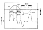
1回のタッピング加工は、タッパがタッピング開始位置から終了位置まで送られる切込み工程と、終了位置から開始位置まで戻される引抜き工程とからなる。そして、切込み工程は、図3に示すように、主軸の回転数が「0」から所定の最大回転数まで加速制御される加速過程、回転数が最大回転数に維持される定速過程及び、回転数が最大回転数から「0」まで減速制御される減速過程とからなる。引抜き工程は、切込み工程と同様に、加速過程、定速過程及び減速過程とからなる。そして、各過程において、回転位相に送り位置が同期するように主軸が制御される。
【0004】
ところで、タッピング加工では、タッパの磨耗程度が寿命となったこと、または、切削屑が詰まったこと等の要因により、切削中のタッパにワークから加わる実切削負荷トルクが過大となることがある。この場合、タッパが折損したりさらに、加工中のタップ穴が損傷することがある。そこで、切込み中に実切削負荷トルクが過大となってもタッパを折損させることなくタッピングを中止するようにした数値制御工作機械が、特開平4−30910号公報に開示されている。
【0005】
この制御工作機械では、検出手段が、タッピング中の主軸回転用モータに加わる実切削負荷トルクを検出する。また、監視手段が、検出された実切削負荷トルクが、記憶手段に記憶されているトルク負荷許容値を超えて過負荷となったか否かを監視する。そして、監視手段によって実切削負荷トルクが過負荷であると判断されると、制御手段が、主軸回転用モータ及び主軸送り用モータを制御して、主軸の回転位相と送り位置とを同期させた状態で、主軸の回転動作及び送り動作を停止させた後、タッピング開始位置まで主軸を復帰動作させる。従って、回転位相の指令値と実際の回転位相との差が過大になる前に、実切削負荷トルクが過大になった状態が検出され、主軸の回転位相と送り位置とが同期する状態で主軸の回転動作及び送り動作が中止されるので、タッパさらにワークが破損することなくタッピングが中止される。
【0006】
この検出手段は、負荷に応じて変化する主軸回転用モータへの供給電流値から、主軸回転用モータに加わる実切削負荷トルクを検出する。詳述すると、図3に示すように、切込み工程における加速過程及び減速過程では、主軸やモータのロータ等の回転部等の慣性が負荷トルクとなって主軸回転用モータに加わる。この慣性による負荷トルクは、実切削負荷トルクよりも顕著に大きな負荷トルクである。一方、主軸の回転数が最大回転数で維持される定速過程で加わる負荷トルクは、殆どタッパに加わる切削負荷トルクだけとなる。そこで、検出手段は、主軸の回転数の指令値が上昇して90%を超えた時点から、指令値が減速となる時点までの、主に定速工程における供給電流値を検出し、検出した供給電流値から実切削負荷トルクの大きさを判断している。尚、引抜き工程における加速過程及び減速過程においても、主軸の慣性による負荷トルクが加わった状態となる。
【0007】
【発明が解決しようとする課題】
しかしながら、加工中のタッパに加わる実切削負荷トルクは、キスラー動力計等を使用したトルク測定で、切込み工程時の減速過程で増大し、減速過程の終了時、即ち、タップ穴の孔底付近で最大となることが分かっている。そして、タッパの折損は、実切削負荷トルクの最大値が過大になったときに発生する。
【0008】
ところが、上記の数値制御工作機械では、加減速中に実切削負荷トルクを検出することができないので、タッパに加わる実切削負荷トルクの最大値を検出することができず、タッパの磨耗程度が寿命となったことを正確に判断することができない。
【0009】
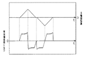
また、アルミニウム等の硬度が低い金属からなるワークに対してタッピング加工を行う場合には、切削抵抗が小さく切削加工が容易であることから、主軸回転数及び送り速度を高速にして加工時間を短縮している。この場合、図10に示すように、主軸が最大回転数で制御される定速過程の継続時間が極端に短くなり、主軸が殆ど加速過程及び減速過程だけで制御される状態となることがある。
【0010】
従って、このような状態でのタッピング加工では、主軸用回転モータに切削負荷トルクだけが加わっている時間が殆どないので、実切削負荷トルクを検出することが困難となる。
【0011】
そして、このようなタッピング加工を行う数値制御工作機械では、検出した実切削負荷トルクに基づいて、タッパの磨耗程度が寿命であることを正確に判断したり、または、切削屑が詰まってタッパに過負荷が加わっている状態であることを判断して適切な処置を行うことができなかった。
【0012】
本発明は、上記問題点を解決するためになされたものであって、その第1の目的は、タッパを駆動する主軸の加減速時にもタッパに過負荷が加わっている状態を検出することができるタッピング装置を提供することにある。
【0013】
また、第2の目的は、第1の目的に加えて、主軸の加減速時にタッパに過負荷が加わっている状態を検出し、タッパの折損またはワークの損傷等を防止することができるタッピング装置を提供することにある。
【0014】
【課題を解決するための手段】
上記問題点を解決するため、請求項1に記載の発明は、タッパが固定された主軸の送り位置と回転位相とを同期させて制御するとともに、主軸回転用モータに加わる負荷を検出するタッピング装置において、タッピング加工時に検出される総負荷と予め設定された基準負荷とから、前記タッパに加わっている実切削負荷または該実切削負荷の負荷増大量を検出する実切削負荷検出手段と、前記実切削負荷または前記負荷増大量のいずれか一方から、予め設定された過負荷判定値を用いて、前記タッパの磨耗程度が寿命であるか否か、切削屑が詰まっている状態であるか否かを判断する過負荷判定手段と、前記主軸を加減速制御して、前記タッパの切込み及び引抜きを行うとともに、前記タッパの磨耗程度が寿命であるか、または、切削屑が詰まっている状態であると判断されたときに、前記主軸を減速制御し該主軸の回転位相と送り位置とを同期させたままの状態で前記タッパの切込みを中止する主軸制御手段とを備え、前記過負荷判定手段は、前記実切削負荷が前記過負荷判定値を超えたときに、切削屑が詰まった状態であると判断し、前記主軸制御手段は、前記主軸を予め設定されている減速度よりも小さい減速度で減速制御して前記タッパの切込みを中止し、前記過負荷判定手段は、タッピング加工毎に切削屑が詰まった状態であると連続して判断された回数が、予め設定された回数を超えたときには、前記タッパの磨耗程度が寿命であると判断し、前記主軸制御手段は、前記主軸を予め設定されている減速度よりも大きい減速度で減速制御して前記タッパの切込みを中止することを要旨とする。
【0015】
請求項2に記載の発明は、請求項1に記載の発明において、前記主軸制御手段は、切削屑が詰まっている状態であると判断された場合、前記主軸を減速制御して前記タッパの切込みを中止し、該主軸を加減速制御して該タッパを加工中のタップ穴から一旦引き抜いた後、そのタップ穴に対するタッピング加工を繰り返して行うことを要旨とする。
【0016】
請求項3に記載の発明は、請求項1に記載の発明において、前記主軸制御手段は、タッパの磨耗程度が寿命であると判断された場合、前記主軸を減速制御して前記タッパの切込みを中止し、該主軸を加減速制御して該タッパを加工中のタップ穴から引き抜いた後、タッピング加工を中止することを要旨とする。
【0017】
請求項4に記載の発明は、請求項2または請求項3に記載の発明において、前記主軸制御手段は、前記主軸を減速制御して前記切込みを中止した後、前記主軸を予め設定されている加減速度よりも小さい加減速度で加減速制御して前記タッパを引き抜くことを要旨とする。
【0023】
(作用)
請求項1に記載の発明によれば、タッピング加工時に主軸回転用モータに加わる負荷が総負荷として検出される。総負荷は、タッパがワークから受ける実切削負荷、主軸と共に回転する回転部の慣性に基づく負荷、軸受等の摩擦部における摩擦抵抗、軸受等の潤滑部における粘性抵抗等からなる。また、タッパに加わる実切削負荷または実切削負荷の増大量を求めるために設定された基準負荷は、実切削負荷を除く各負荷の総和が、総負荷における実切削負荷を除く各負荷の総和と同じとなる。さらに、基準負荷が、実切削負荷を含むものである場合には、総負荷との差分が実切削負荷の増大量となる。そして、主軸の送り位置と回転位相に対応する実切削負荷または実切削負荷の増大量が、同じ切削位置での総負荷と空運転時基準負荷との差分として求められる。従って、主軸等の慣性が負荷として加わる加減速時にも実切削負荷の増大量が検出される。
【0027】
加えて、切込み中に、タッパの磨耗程度が寿命となったり、または、切削屑が詰まると、タッパに加わる実切削負荷、または、以前の実切削負荷からの負荷増大量が過大な値となる。過大になった実切削負荷または負荷増大量と、予め設定された基準切削負荷とから、タッパの磨耗程度が寿命となったこと、または、切削屑が詰まったことが判断される。そして、タッパが切込み中のタップ穴に沿ったままで切込みが停止される。従って、タッパの切込み中にタッパの磨耗程度が寿命となったり、または、切削屑が詰まった状態となったことによってタッパに加わる実切削負荷あるいは負荷増大量が過大になると、切込み中のタップ穴が損傷しない状態でタッパの切込みが中止される。
【0028】
また、切込み中に、切削屑が詰まった状態となったことによってタッパに加わる切削負荷が過大になった場合、タッパの回転速度をより緩やかに低下させることにより、減速過程中における切削屑の排出が促進される。従って、タッパの切込み中に切削屑が詰まった状態となっても、タッパに加わる実切削負荷が抑制された状態で切込みが中止される。さらに、切込み時に磨耗程度が寿命であると判断されたタッパがより大きな減速度で減速制御されて停止するので、減速中にタッパに加わる実切削負荷が軽減される。
【0029】
請求項2記載の発明によれば、請求項1に記載の発明の作用に加えて、実切削負荷に基づいて切削屑が詰まった状態であることが判断されると、タッパが一旦引き抜かれた後、タッピング加工が繰り返し行なわれる。従って、切削屑が詰まっただけではタッピング加工が中止されず、切削屑を排出しながらタッピング加工が繰り返し行われる。
【0030】
請求項3に記載の発明によれば、請求項1に記載の発明の作用に加えて、切込み中にタッパの磨耗程度が寿命となったときには、加工中のタップ穴からタッパを引き抜いてタッピング加工を終了することができる。
【0031】
請求項4に記載の発明によれば、請求項2または請求項3に記載の発明の作用に加えて、タッパの磨耗程度が寿命であると判断されるか、または、切削屑が詰まった状態であると判断されて切込みが中止された後、より小さな加減速度で主軸が加減速制御されて引き抜かれるので、引抜き時にタッパに加わる実切削負荷が軽減される。
【0032】
【発明の実施の形態】
(第1の実施の形態)
以下、本発明をCNCタッピングマシンに具体化した第1の実施の形態を図1〜図9に従って説明する。
【0033】
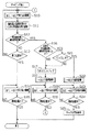
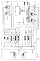
図2に示すように、タッピング装置としてのCNCタッピングマシン10は、加工装置11及び制御装置12とからなる。
加工装置11は、X軸及びY軸方向に移動可能なワークテーブル13、X軸及びY軸方向の所定位置に固定配置されタッパTが装着される主軸14、主軸回転用モータ15、主軸送り用モータ16、X軸駆動用モータ17、Y軸駆動用モータ18等を備える。そして、加工装置11は、X軸駆動用モータ17及びY軸駆動用モータ18によってワークテーブル13をX軸及びY軸方向に移動させて、X軸及びY軸座標上の位置で設定されるワークWの所定位置を主軸14に対して位置決めする。また、加工装置11は、タッパTを装着した主軸14をZ軸方向に移動させることで、位置決めされたワークWの所定位置にタッピング加工を行うようになっている。
【0034】
また、加工装置11は、主軸14に対して位置決めするX軸座標上でのワークテーブル13の位置を検出するX軸座標検出器19、同じくY軸座標上でのワークテーブル13の位置を検出するY軸座標検出器20を備えている。また、Z軸周りでの主軸14の回転位相を検出する回転位相検出器21、及び、Z軸座標上での主軸14の送り位置を検出するZ軸座標検出器22を備えている。そして、加工装置11は、主軸14に対して位置決めするワークテーブル13のX,Y座標軸上の位置を逐次検出するとともに、主軸14のZ軸座標上での送り位置、及び、Z軸周りでの回転位相を逐次検出する。
【0035】
制御装置12は、コンピュータ23、駆動装置24、負荷検出装置25等を備える。本実施の形態では、コンピュータ23が過負荷判定手段及び主軸制御手段であり、コンピュータ23及び負荷検出装置25が実切削負荷検出手段を構成する。
【0036】
駆動装置24は、主軸駆動装置26、主軸送り駆動装置27、X軸駆動装置28及びY軸駆動装置29を備える。主軸駆動装置26は、主軸回転用モータ15を駆動制御する。主軸送り駆動装置27は、主軸送り用モータ16を駆動制御する。また、X軸駆動装置28はX軸駆動用モータ17を、Y軸駆動装置29はY軸駆動用モータ18をそれぞれ駆動制御する。
【0037】
コンピュータ23は、中央処理装置30、記憶装置31、入力装置32、表示装置33及び入出力装置34等を備える。
記憶装置31は、主軸回転用モータ15、主軸送り用モータ16、X軸駆動用モータ17及びY軸駆動用モータ18を各駆動装置26〜29を介して駆動制御するための制御プログラムを記憶している。また、記憶装置31は、ワークW毎に設定された複数のタッピング加工位置の加工順序、及び、各タッピング加工のタッピング加工条件が設定された作業プログラムを記憶している。タッピング加工条件としては、X,Y軸座標上でのタッピング位置、Z軸座標上のタップ終了位置及びタッピング開始位置、タッピング開始位置での主軸14の回転位相、タッパTのねじピッチ量、最大主軸回転数、タップサイズ等が設定されている。
【0038】
中央処理装置30は、記憶装置31に記憶されている制御プログラムに従い、X,Y軸駆動装置28,29を介してX軸駆動用モータ17及びY軸駆動用モータ18を駆動制御し、ワークWのX,Y軸座標上の所定のタッピング位置を主軸14に対して位置決めする制御を行う。このとき、中央処理装置30は、制御プログラムに従い、X軸座標検出器19及びY軸座標検出器20の各検出結果に基づいてソフトウェアサーボによるフィードバック制御を行う。
【0039】
また、中央処理装置30は、制御プログラムに従い、X軸及びY軸座標上の所定位置において主軸駆動装置26及び主軸送り駆動装置27を介して主軸回転用モータ15及び主軸送り用モータ16を駆動制御し、作業プログラムに設定されているタッピング加工条件で、切込み工程及び引抜き工程からなるタッピング加工を行うように回転位相・回転数制御、及び、送り位置・送り速度制御を行う。即ち、中央処理装置30は、作業プログラムのタッピング加工条件で指定されたタッピング開始位置での回転位相、タッパTのねじピッチ量及び最大主軸回転数に基づき、回転位相と送り量とを同期させた回転位相・回転数制御、及び、送り位置・送り速度制御を行う。
【0040】
また、中央処理装置30は、制御プログラムに従い、タッピング開始位置からタッピング終了位置までタッパTを送る切込み制御の間に、主軸回転数及び送り速度を、主軸回転数が「0」からタッピング加工条件で指定される最大主軸回転数となるまで予め設定されている回転加速度で増大させた後、最大主軸回転数から「0」まで同じ大きさの回転加速度で減少させる。尚、切込み時の加速過程は、タッパTが切込み状態に入る前に終了するか、または、加速中にタッパTが切込み状態に入るように、タッピング開始位置または回転加速度が設定されている。同様に、中央処理装置30は、制御プログラムに従い、タッピング終了位置からタッピング開始位置までタッパTを戻す引抜き制御の間に、主軸回転数を「0」から最大主軸回転数まで予め設定されている回転加速度で増大させた後、最大主軸回転数から「0」まで同じ大きさの回転加速度で減少させる。このとき、中央処理装置30は、切込み制御及び引抜き制御において、制御プログラムに従い、回転位相検出器21及びZ軸座標検出器22の各検出結果に基づいてソフトウェアサーボによるフィードバック制御を行う。
【0041】
中央処理装置30は、主軸14の切込み時の加速制御を、予め設定されている第1の回転加速度(以下、第1の加速度という。)α1及び第2の回転加速度(以下、第2の加速度という。)α2のいずれかで行ない、同じく減速制御を、予め設定されている第1の回転減速度(以下、第1の減速度という。)−α1、第2の回転減速度(以下、第2の減速度という。)−α2及び第3の回転減速度(以下、第3の減速度という。)−α3のいずれかで行う。第1の加速度α1及び第1の減速度−α1は通常使用するために設定されたものであって同じ大きさであり、第2の加速度α2及び第2の減速度−α2は、タッパTに加わる実切削負荷が過大になったときに使用されるものであって同じ大きさであるとともに第1の加速度α1及び第1の減速度−α1よりも(絶対値が)小さい値に設定されている。また、第3の減速度−α3は、第1の減速度−α1よりも(絶対値が)大きい値に設定されている。
【0042】
負荷検出装置25は、主軸14が回転駆動されているときに、主軸回転用モータ15が受ける回転負荷トルクに応じて大きさが変化する主軸回転用モータ15の駆動電流値を検出してコンピュータ23に出力する。尚、タッピング加工時に主軸回転用モータ15が受ける回転負荷トルクは、タッパTがワークWから受ける切削負荷による実切削負荷トルク、主軸14の加速時及び減速時に主軸14と共に回転する回転部(タッパT、チャック、回転軸、主軸回転用モータの回転子等)の慣性に基づく負荷トルク、軸受等の摩擦部における摩擦抵抗、軸受等の潤滑部における粘性抵抗等を主とする総負荷トルクである。
【0043】
(実切削負荷の検出)
中央処理装置30は、制御プログラムに従い、負荷検出装置25が検出する駆動電流値から、主軸回転用モータ15に加わる総負荷トルクを逐次検出する。図3は、1回のタッピング加工工程における総負荷トルク及び主軸回転数の時間特性を示すグラフである。尚、このグラフに示す特性は、切込み時に、主軸14の加速過程の終了後に、タッパTが切込み状態に入るように設定されている場合のものである。
【0044】
図3のグラフに示すように、切込み時の加速過程で検出される総負荷トルクは、実切削負荷トルクを含まないものとなり、定速時に検出される総負荷トルクは、主軸14を含む回転部の慣性に基づく負荷トルクを含まないものとなる。さらに、切込み時の減速過程で検出される総負荷トルクは、実切削負荷トルクと、回転部の慣性に基づく負荷トルクとが合成されたものとなる。また、引抜き時の加速過程で検出される総負荷トルクは、回転部の慣性に基づく負荷トルクと、切削屑の詰まり等による抵抗負荷トルクとが合成されたものとなり、定速時に検出される総負荷トルクは、主軸14を含む回転部の慣性に基づく負荷トルクを含まないものとなる。さらに、引抜き時の減速過程で検出される総負荷トルクは、回転部の慣性に基づく負荷トルクを含むものとなる。
【0045】
また、中央処理装置30は、制御プログラムに従い、入力装置32での入力操作によって指定されたタッピング加工時に、回転位相及び送り位置に対応して検出する総負荷トルクを、回転位相及び送り位置に対応させた基準負荷トルクのデータとして保存する。さらに、中央処理装置30は、制御プログラムに従い、各タッピング加工時に、回転位相及び送り位置に対応して検出する総負荷トルクの値から、保存している総負荷トルクのデータの同じ回転位置及び送り位置における基準負荷トルクの値を差し引いた値を、切削時にタッパTに加わる同回転位相及び送り位置における実切削負荷トルクの増大量として求める。
【0046】
即ち、回転位相及び送り位置に対応する基準負荷トルクのデータは、そのときのタッパTの摩耗程度に応じてワークWから受ける切削負荷による実切削負荷トルク、主軸14の加速時及び減速時に主軸14と共に回転する回転部の慣性に基づく負荷トルク、軸受等の摩擦部における摩擦抵抗、軸受等の循環部における粘性抵抗等からなる。また、その後の各タッピング加工時に検出する総負荷トルクは、タッパTの磨耗程度が進行したことによる実切削負荷トルクの増大分だけ増大したものである。従って、中央処理装置30は、各タッピング加工時に検出する総負荷トルクから基準負荷トルクを差し引くことにより、そのときのタッパTの磨耗程度の進行分に応じた実切削負荷トルクの負荷トルク増大分を検出する。
【0047】
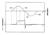
また、基準負荷トルクが、実際にタッピング加工を行なっていない空運転時に検出した空運転時基準負荷トルクである場合には、空運転時基準負荷トルクは、図4に示すように、主軸14の加速時及び減速時に主軸14と共に回転する回転部の慣性に基づく負荷トルク、軸受等の摩擦部における摩擦抵抗、及び、軸受等の循環部における粘性抵抗等からなり、実切削負荷トルクが含まれていないものとなる。従って、中央処理装置30は、総負荷トルクから空運転時基準負荷トルクを差し引くことにより、図5に示すように、そのときのタッパTの磨耗程度に応じた実切削負荷トルク自体を検出する。尚、総負荷トルクから基準負荷トルクを差し引いて求められる実切削負荷トルクは、タッピング加工時に実際にタッパTに加わる切削負荷トルクをキスラー動力計等で測定した測定値と良く一致する。
【0048】
タッピング加工時において検出する実切削負荷トルクは、主軸14が定速制御されている状態での切込み中には、ほぼ一定の大きさとなり、減速制御されている状態での切込み中には、主軸回転数が小さくなるほど次第に大きくなる特性を示す。従って、通常、実切削負荷トルクは、タッピング終了位置の手前で最大値となる。さらに、実切削負荷トルクは、切削屑が詰まった状態となったときには、急激に増大する特性を示す。
【0049】
(タッピング加工)
次に、中央処理装置30が行うタッピング加工の手順を、図1のフローチャートに従って説明する。即ち、このタッピング加工を行う前に、タッピング加工条件で指定されているX軸及びY軸座標上のワークWの所定位置が主軸14に対して位置決めされており、また、タッピング開始位置に主軸14が所定の回転位相で配置されている。また、基準負荷トルクとして、空運転時基準負荷トルクが保存されているものとする。
【0050】
中央処理装置30は、タッピング加工制御として、先ず、ステップ10で、主軸回転用モータ15及び主軸送り用モータ16を駆動制御して回転位相及び送り位置を同期させた状態で主軸14を切込み制御する。このとき、中央処理装置30は、第1の加速度α1及び第1の減速度−α1で主軸14の回転速度を加減速するように制御を行う。この第1の加速度α1及び第1の減速度−α1は、タッピングを行うワークW及びタッパTに対し最大主軸回転数と共に設定される値であって、例えば、磨耗程度が寿命でないタッパTが受ける実切削負荷トルクがタッパTの許容範囲内となる値であって、かつ、できるだけ大きな値である。
【0051】
詳述すると、タッパTの切込み時には、回転加速度及び回転減速度が大きい程、また、タッパTの磨耗程度が大きい程、切削屑が排出され難くなって加工中のタップ穴内に停滞する。その結果、停滞している切削屑の詰まりによって、タッパTに加わる実切削負荷トルクが過度に増大する。そこで、切削屑が詰まっておらず、また、タッパTの磨耗程度が寿命でない状態では、第1の加速度α1及び第1の減速度−α1で加減速制御を行うことにより、切込み及び引抜きが短い時間で終了するようにする。
【0052】
中央処理装置30は、主軸14を切込み制御している間に、ステップ11で、逐次検出する総切削負荷トルクから空運転時基準負荷トルクを差し引いた実切削負荷トルクを逐次演算する。そして、中央処理装置30は、ステップ12で、演算した実切削負荷トルクが、予め設定されている過負荷判定値T0を超える大きさであるか否かを判断する。過負荷判定値T0は、第1の加速度α1で主軸14を加減速制御したときに、タッパTが受ける実切削負荷トルクが許容範囲の上限領域の大きさであることを判断するために予め設定されている値である。
【0053】
中央処理装置30は、ステップ12で実切削負荷トルクが過負荷判定値T0以下であったときには、タッパTの磨耗程度が寿命ではなく、また、切削屑が詰まってタッパTに許容範囲の上限領域の切削負荷が加わっていないとして、ステップ13で、切込み制御をタッピング終了位置まで行う。
【0054】
中央処理装置30は、実切削負荷が過負荷判定値T0以下のままでタッピング終了位置まで切込み制御を行なった後は、ステップ14及び15で、第1の加速度α1及び第1の減速度−α1で主軸14を加減速制御して、タッピング終了位置からタッピング開始位置まで引抜き制御する。
【0055】
一方、中央処理装置30は、ステップ12で、実切削負荷トルクが過負荷判定値T0を超える大きさであったときには、タッパTの磨耗程度が寿命となったか、または、切削屑が詰まってタッパTに許容範囲の上限領域の切削負荷トルクが加わったかのいずれかであると判断する。この場合、中央処理装置30は、ステップ16で、前回行なったタッピング加工において、実切削負荷トルクが過負荷判定値T0を超えたか否かを判断する。
【0056】
中央処理装置30は、ステップ16で前回行なったタッピング加工において実切削負荷が過負荷判定値T0を超えていなかったときには、ステップ17でカウント値Cをカウントアップした後、ステップ18で、第2の減速度−α2で主軸14を減速制御して、回転位相と送り位置とを同期させたままで停止させる。第2の減速度−α2は、第1の減速度−α1で減速したときにはタッパTが受ける実切削負荷トルクがタッパTの許容範囲を超える大きさとなる場合であっても、第2の減速度−α2で減速したときには実切削負荷トルクが許容範囲となるように設定されている。
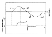
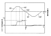
【0057】
ステップ18において、中央処理装置30は、主軸14が最大主軸回転数で制御されているときには、図6に示すように、その回転数及び送り速度から第2の減速度−α2で減速制御を行ない、また、主軸14の制御状態が第1の減速度−α1による減速状態であるときには、図7に示すように、第1の減速度−α1を第2の減速度−α2に切り換えて減速制御を行う。このことにより、中央処理装置30は、実切削負荷が過負荷判定値T0を超えた原因が、切削屑が詰まったことによるものと判断した場合には、第2の減速度−α2で減速制御して停止させることにより、切込み中のタッパTに加わる実切削負荷トルクがそれ以上増大しないようにする。
【0058】
その後、中央処理装置30は、ステップ19及び20で、図6,7に示すように、第2の加速度α2及び第2の減速度−α2で主軸14を加減速制御し、停止したZ軸座標上の位置からタッピング開始位置まで主軸14を引抜き制御する。そして、中央処理装置30は、X軸及びY軸座標上での同じ位置でタッピング加工を再び行う。中央処理装置30は、切込み中に停止させたタッパTを第2の加速度α2及び第2の減速度−α2で加減速制御することにより、引抜き中のタッパTに加わる実切削負荷トルクがそれ以上増大しないようにする。
【0059】
従って、中央処理装置30は、検出した実切削負荷トルクに基づき、タッパTに切削屑の詰まりによる過負荷が加わったと判断したときには、タッピング加工を途中で中断し、主軸14を一旦タッピング開始位置まで戻してから再びタッピング加工を行う。
【0060】
一方、中央処理装置30は、ステップ16で前回行なったタッピング加工において実切削負荷トルクが過負荷判定値T0を超えていたときには、ステップ21で、カウント値Cが予め設定されている寿命判定値CLを超えているか否かを判断する。寿命判定値CLは、今回のタッピング加工時に実切削負荷トルクが過負荷判定値T0を超えた原因が、切削屑の詰まりによる切削負荷の上昇でなく、タッパTの磨耗程度が寿命となったことによるものであると判断するために設定されている。
【0061】
中央処理装置30は、ステップ21でカウント値Cが寿命判定値CL以下であったときには、タッパTの磨耗程度が寿命でないと判定し、ステップ17に進む。そして、前述の場合と同様にして、切り込み工程を中断するとともに、ワークWの同一箇所に再度タッピング加工を行う。
【0062】
従って、中央処理装置30は、タッパTに加わった過負荷が、確実にタッパTの磨耗程度が寿命となったことによるものであると判断しない内は、切削屑の詰まりによるものであるとみなしてタッピング加工を中断し、主軸14をタッピング開始位置まで戻してから再びタッピング加工を行う。
【0063】
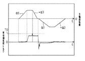
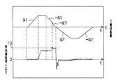
また、中央処理装置30は、ステップ21でカウント値Cが寿命判定値CLを超えた場合には、タッパTの磨耗程度が寿命であると判断して、ステップ22で、第3の減速度−α3で主軸14を減速制御して、回転位相と送り位置とを同期させたままで停止させる。ステップ22において、中央処理装置30は、主軸14の制御状態が定速制御状態であるときには、図8に示すように、その回転数及び送り速度から第3の減速度−α3で減速制御を行ない、また、主軸14の制御状態が第1の減速度−α1による減速状態であるときには、図9に示すように、第1の減速度−α1を第3の減速度−α3に切り換えて減速制御を行う。
【0064】
切込み中にタッパTの磨耗程度が寿命となった場合、そのまま切込みを継続すると、実切削負荷トルクがさらに増大してタッパTの折損に至る可能性がある。中央処理装置30は、第1の減速度−α1よりも大きな第3の減速度−α3で主軸14を減速制御して停止させることによって切込みを早く終了させ、タッパTにできるだけ大きな実切削負荷トルクが加わらないようにする。
【0065】
その後、中央処理装置30は、ステップ23及び24で、図8,9に示すように、第2の加速度α2及び第2の減速度−α2で主軸14を加減速制御し、停止したZ軸上の位置からタッピング位置まで主軸14を引抜き制御する。そして、中央処理装置30は、ステップ25で表示装置33を制御してタッパTの磨耗状態が寿命となったことの表示を行う。
【0066】
従って、中央処理装置30は、検出した実切削負荷トルクに基づき、タッパTの磨耗程度が寿命であることによる過負荷が加わったと判断したときには、タッピング加工を途中で中止し、主軸14を引抜き制御した後、そのままタッピング加工を終了する。
【0067】
次に、以上のように構成されたCNCタッピングマシンの作用について説明する。
基準負荷値のデータを作成して保存するときには、空運転でタッピング加工を行い、そのときに検出される総負荷のデータを、入力装置32での入力操作によってコンピュータ23に基準負荷として保存させる。
【0068】
タッピング加工においては、中央処理装置30は、タッパTの切込み制御時に、回転位置及び送り位置に対応して逐次検出される総負荷トルクから同位置における空運転時基準負荷トルクを差し引いた実切削負荷トルクを逐次演算する。従って、主軸14等の慣性が負荷として加わる加減速時にも実切削負荷トルクが検出される。また、切込み時における主軸14の減速過程で最大となる実切削負荷トルクの最大値が検出される。
【0069】
切込み制御時に検出された実切削負荷トルクが、予め設定されている過負荷判定値T0を超えたときには、中央処理装置30は、切削屑が詰まって実切削負荷トルクが一時的に増大した状態であるか、または、タッパTの磨耗程度が寿命となったと判断する。そして、主軸14を回転位相と送り位置とを同期させたままの状態で減速制御して停止させ、切込み制御を中止する。従って、切込み制御時に、切削屑が詰まって実切削負荷トルクが一時的に増大したとき、または、タッパTの磨耗程度が寿命となったときには、切込み中のタップ穴が損傷しない状態でタッパTの切込みが中止される。
【0070】
切込み制御時に検出された実切削負荷トルクが、予め設定されている過負荷判定値T0を超えたとき、中央処理装置30は、タッピング加工毎の切込み時に、実切削負荷トルクが過負荷判定値T0を超えた回数が所定の寿命判定値CL以下である場合には、各タッピング加工時に切削屑が詰まって実切削負荷トルクが一時的に増大したと一旦判断する。そして、タッピング終了位置の手前で停止させた主軸14を、第2の加速度α2及び第2の減速度−α2で加減速制御してその停止位置からタッピング開始位置まで引抜き制御する。従って、切込み制御時に、切削屑が詰まって実切削負荷トルクが一時的に増大したときには、引抜き時にタッパTに加わる実切削負荷トルクが抑制される。
【0071】
さらに、切込み時に実切削負荷トルクが過負荷判定値T0を超えた回数が寿命判定値CL以下である場合、中央処理装置30は、タッピング終了位置の手前で主軸14を停止させた後、タッピング開始位置まで引抜き制御した主軸14を、再び第1の加速度α1及び第1の減速度−α1で加減速制御してタッピング開始位置からタッピング終了位置に向かって切込み制御する。従って、切込み制御時に、切削屑が詰まっただけではタッピング加工が中止されず、同じ位置におけるタッピング加工が自動で繰り返し行われる。
【0072】
また、切込み制御時に検出された実切削負荷トルクが、予め設定されている過負荷判定値T0を超えたとき、タッピング加工毎の切込み時に、実切削負荷トルクが過負荷判定値T0を超えた回数が寿命判定値CLを超えた場合、中央処理装置30は、タッパTの磨耗状態が寿命であると判断する。そして、主軸14を第1の減速度−α1よりも大きな第3の減速度−α3で減速制御して停止させる。従って、切込み時にタッパTの磨耗程度が寿命であると判断された場合、減速中にタッパTに加わる実切削負荷トルクが軽減される。
【0073】
さらに、タッピング加工毎の切込み時に、実切削負荷トルクが過負荷判定値T0を超えた回数が寿命判定値CLを超えた場合、減速制御して停止させた主軸14を、第2の加速度α2及び第2の減速度−α2で加減速制御してタッピング開始位置まで引抜き制御した後、タッピング加工を中止する。従って、切込み制御時に、タッパTの磨耗程度が寿命となったときには、引抜き時にタッパTが折損しないように加わる実切削負荷トルクが抑制される。
【0074】
以上詳述した本実施の形態によれば、以下に記載の各効果を得ることができる。
(1) タッピング加工時に検出される総負荷トルクと、タッパTに加わる実切削負荷トルクの総負荷トルクにおける負荷トルク増大量を求めるために設定された基準負荷トルクとから、タッパTに加わる実切削負荷トルクを求めるようにした。
【0075】
従って、主軸14等の慣性が負荷トルクとして加わる加減速中にも実切削負荷トルクを検出することができ、加減速中のタッパTに過負荷が加わっている状態を検出することができる。
【0076】
(2) 主軸14に加わる実切削負荷トルクが最大となる切込み時の減速中の実切削負荷トルクを検出することができるので、実切削負荷トルクの最大値を検出することができる。従って、タッパTの磨耗程度が寿命であること、または、切削屑が詰まった状態であることを正確に判断できる。
【0077】
また、主軸14が一定回転数及び送り速度で駆動制御される時間が極少ないような高速タッピング加工においても、タッパTに加わる実切削負荷トルクを検出することができる。
【0078】
(3) 空運転でタッピング加工を行なったときに検出される空運転時基準負荷トルクと総負荷トルクとから、負荷トルク増大量でなく実切削負荷トルクを直接求めるようにした。従って、実切削負荷トルクを判定するので、タッパTの磨耗程度が寿命であること、または、切削屑の詰まった状態を容易に判断することができる。
【0079】
(4) 検出する実切削負荷トルクに対して予め設定された過負荷判定値T0から、コンピュータ23が、切削屑が詰まった状態、及び、タッパTの磨耗程度が寿命であることを判断する。そして、主軸14を減速制御して、主軸14の回転位相と送り位置とを同期させたままで切込み制御を中止するようにした。
【0080】
従って、切込み中のタッパTの磨耗程度が寿命となったり、または、切削屑が詰まった状態となったことによってタッパTに加わる実切削負荷トルクが過大になると、タッパTに加わる実切削負荷トルクが抑制された状態で切込みが中止される。その結果、切込み中に、タッパTの磨耗程度が寿命となったり、または、切削屑が詰まった状態となったときに、タッパTが折損したりタップ穴が損傷しないようにすることができる。
【0081】
(5) 切込み時に切削屑が詰まった状態であることをコンピュータ23が実切削負荷トルクに基づいて判断し、第1の減速度−α1よりも小さい第2の減速度−α2で減速制御を行なって停止させ、切込みを中止するようにした。
【0082】
従って、切込み中に切削屑が詰まった状態となったときに、切削屑の詰まりが緩和される状態で切込みが中止されるので、切込み時に切削屑が詰まってもタッパTの折損さらにタップ穴の損傷を防止することができる。
【0083】
(6) 切込み時の減速制御の途中であっても、検出した実切削負荷トルクが過負荷判定値T0を超えたときには、コンピュータ23は、通常の第1の減速度−α1よりも小さい第2の減速度−α2で主軸14を減速制御するようにした。
【0084】
従って、実切削負荷トルクが最大となる切込み時の減速過程において切削屑が詰まり難いように切込みが中止されるので、切込み時における切削屑の詰まりによるタッパTの折損さらにタップ穴の損傷をより一層確実に防止することができる。
【0085】
(7) 切削屑が詰まって実切削負荷トルクが過大になった状態であることを、コンピュータ23が実切削負荷トルクに基づいて判断し、タッピング加工を中止したタップ穴に対するタッピング加工を繰り返し行うようにした。
【0086】
従って、切削屑が詰まっただけではタッピング加工が中止されず繰り返しタッピング加工が行われるので、切込み時に切削屑が一旦詰まってもタッパTを折損することなくタップ穴を自動等で確実に加工形成することができる。
【0087】
(8) 切込み時にタッパTの磨耗程度が寿命であると判断されたときには、通常より大きな第3の減速度−α3で主軸14を減速制御して停止させるようにした。従って、切込み中にタッパTの磨耗程度が寿命となっても、タッパTに加わる実切削負荷トルクが軽減される状態で切込みが中止されるので、切込み時にタッパTが寿命となってもタッパTの折損さらにタップ穴の損傷を防止することができる。
【0088】
(9) 実切削負荷トルクに基づいて切込みを中止した後、コンピュータ23は、通常より小さい第2の加速度α2及び第2の減速度−α2で主軸14を加減速制御してタッパTを引き抜くようにした。
【0089】
従って、タッパTの磨耗程度が寿命となるか、切削屑が詰まった状態となって切込みが中止された後、引抜き時にタッパTに加わる実切削負荷が軽減されるので、タッパTの折損及びタップ穴の損傷を招くことなくタッパTを引き抜くことができる。
【0090】
(10) 実切削負荷トルクが過負荷判定値T0を超えたとき、切削屑が詰まった状態であると判断して切込み制御を中止し、タッパTがタップ穴の外側に配置されるまで主軸14を引抜き制御した後、タッピング加工中のタップ穴に対するタッピング加工を繰り返し行う。そして、同じタップ穴に対するタッピング加工毎に実切削負荷トルクが過負荷判定値T0を連続して超える回数が予め設定した寿命判定値CLを超えたときには、タッパTの磨耗程度が寿命であると改めて判断し、主軸14の切込み制御を中止し、主軸14を引き抜いた後にタッピング加工を停止するようにした。
【0091】
従って、切削屑が詰まったときには、タッパTの折損さらにタップ穴の損傷を招くことなく加工中のタップ穴に対するタッピング加工を自動で継続することができ、また、切込み中にタッパTの磨耗程度が寿命となったときには、加工中のタップ穴からタッパTを引き抜いてタッピング加工を終了することができる。
【0092】
(第2の実施の形態)
次に、本発明を具体化した第2の実施の形態を図11に従って説明する。尚、本実施の形態は、前記第1の実施の形態におけるタッピング加工の制御内容を変更したことのみが第1の実施の形態と異なる。従って、第1の実施の形態と同じ構成については、符号を同じにしてその説明を省略し、タッピング加工の制御内容のみについて詳述する。
【0093】
中央処理装置30が行うタッピング加工の手順を、図11のフローチャートに従って説明する。尚、本実施の形態では、基準負荷トルクとして、主軸14と共に回転する回転部全体の慣性質量と、主軸14の回転数とから求めた計算基準負荷トルク値が予め保存されている。
【0094】
中央処理装置30は、タッピング加工制御として、先ずステップ30で、主軸回転用モータ15及び主軸送り用モータ16を駆動制御して回転位相及び送り位置を同期させた状態で主軸14を切込み制御する。このとき、中央処理装置30は、第1の加速度α1及び第1の減速度−α1で主軸14を加減速制御する。
【0095】
中央処理装置30は、主軸14を切込み制御している間に、ステップ31で、逐次検出する総切削負荷トルクから計算基準負荷トルクを差し引いた実切削負荷トルクを逐次演算する。そして、中央処理装置30は、ステップ32で、演算した実切削負荷トルクが、予め設定されている過負荷判定値T0を超える大きさであるか否かを判断する。本実施の形態では、過負荷判定値T0は、切込み時にタッパTに加わる実切削負荷トルクからタッパTの磨耗程度が寿命であるか否かを判定することができる値に設定されている。
【0096】
中央処理装置30は、ステップ32で実切削負荷トルクが過負荷判定値T0以下であったときには、タッパTの磨耗程度が寿命ではないと判断し、ステップ33で切込み制御をタッピング終了位置まで行う。
【0097】
中央処理装置30は、実切削負荷トルクが過負荷判定値T0以下のままでタッピング終了位置まで切込み制御を行なった後は、ステップ34及び35で、第1の加速度α1及び第1の減速度−α1で主軸14を加減速制御して、タッピング終了位置からタッピング開始位置まで引抜き制御する。
【0098】
一方、中央処理装置30は、ステップ32で実切削負荷トルクが過負荷判定値T0を超えたときには、タッパTの磨耗程度が寿命まで進行したと判断し、ステップ36で第3の加速度−α3で減速制御して、回転位相と送り位置とを同期させたままで主軸14を停止させる。
【0099】
そして、中央処理装置30は、ステップ37及び38で、第2の加速度α2及び第2の減速度−α2で主軸14を加減速制御し、停止したZ軸座標上の位置からタッピング開始位置まで主軸14を引抜き制御する。そして、中央処理装置30は、ステップ39で表示装置33を制御して、タッパTの磨耗程度が寿命となったことの表示を行う。
【0100】
従って、中央処理装置30は、検出した実切削負荷トルクに基づき、タッパTの磨耗程度が寿命であることによる負荷トルクが加わったと判断したときには、タッピング加工を中止して主軸14を引抜き制御した後、そのままタッピング加工を終了する。
【0101】
以上のように構成されたCNCタッピングマシンの作用について説明する。
計算基準負荷トルクのデータは、予めコンピュータに記憶させる。
中央処理装置30は、切込み制御時に、検出された総負荷トルクと計算基準負荷トルクとから実切削負荷トルクを求める。中央処理装置30は、逐次演算する実切削負荷トルクが過負荷判定値T0を超えたときには、タッパTの磨耗程度が寿命となったと判断する。そして、主軸14をより大きな第3の加速度−α3で減速制御して停止させ、切込み制御を中止する。従って、切込み時に、タッパTの磨耗程度が寿命となったときには、タッパTに加わる負荷トルクが抑制された状態で切込みが中止される。
【0102】
以上詳述した本実施の形態のCNCタッピングマシンによれば、前記第1の実施の形態における(1),(2),(8),(9)に記載の各効果と、以下に記載する効果を得ることができる。
【0103】
(11) 少なくとも主軸14を含む回転部の慣性質量と、主軸14の回転数とから実切削負荷トルクを含まない計算基準負荷トルクを計算する。そして、この計算基準負荷トルクと、逐次検出する総負荷トルクとから実切削負荷トルクを直接求めるようにした。従って、実切削負荷トルクを直接判定するので、タッパTの磨耗程度が寿命であること、または、切削屑が詰まった状態であることを容易に判断することができる。
【0104】
(12) 検出する実切削負荷トルクに対して予め設定された過負荷判定値T0から、コンピュータ23が、タッパTの磨耗程度が寿命であるか否か判断する。そして、寿命であったときには、主軸14をより大きな第3の減速度−α3で減速制御して、回転位相と送り位置とを同期させたままで切込み制御を中止するようにした。従って、タッパTの切込み中にタッパTの磨耗程度が寿命となると、タッパTに加わる実切削負荷トルクが抑制された状態で切込みが中止される。その結果、切込み中のタッパTの磨耗程度が寿命となっても、タッパTの折損またはタップ穴の損傷を招くことなくタッピング加工を中止することができる。
【0105】
以下、本発明を具体化した上記実施の形態以外の実施の形態を別例として列挙する。
・ 第1の実施の形態で、空運転時基準負荷トルクを、切込み工程における減速過程を含む加工過程にのみ設定し、コンピュータ23が、この加工工程での実切削負荷トルクを検出するようにしてもよい。この場合でも、タッパに加わる実切削負荷トルクが極大となる切込み工程の減速過程における実切削負荷トルクを検出することができるので、タッパTの磨耗程度が寿命であるか否かを正確に判断することができる。
【0106】
同様に、第2の実施の形態で、計算基準負荷トルクを、切込み工程における減速過程を含む加工過程にのみ設定し、この加工工程での実切削負荷トルクを検出するようにしてもよい。この場合でも同じ効果がある。
【0107】
・ 基準負荷として、空運転時基準負荷トルクまたは計算基準負荷トルクを用いる代わりに、実切削負荷トルクを検出するときに使用するタッパTと同じ仕様(タップサイズ、ねじピッチ量等)のタッパTを用いてタッピング加工を実際に行なったときに検出する総負荷トルクを基準負荷(基準総負荷)トルクとしてもよい。そして、実切削負荷トルクを検出するときに検出する総負荷トルクから基準総負荷トルクを差し引いて、実切削負荷トルクの負荷トルク増大量を求める。即ち、負荷トルク増大量は、タッパTの磨耗程度の差に対応した実切削負荷トルクの増大量である。この負荷トルク増大量から、予め設定した過負荷判定値を用いて、タッパTの磨耗程度が寿命であるか否か、または、切削屑が詰まっている状態であるか否かを判断するようにしてもよい。
【0108】
・ 第1及び第2の実施の形態では、主軸14の加速及び減速が一定の加速度(α1)及び減速度(−α1)で行われるようにしたが、このような加速または減速に限らず、その他例えば、一次関数的または二次関数的に増大または減少する加速度及び減速度で加速及び減速が行なわれるようにしてもよい。この場合には、加速過程または減速過程における平均加速度または平均減速度を、より小さく、または、より大きくすればよい。即ち、切込み中に、タッパTの磨耗程度が寿命であるか、または、切削屑が詰まった状態であると判断されたときには、減速過程をより小さな平均減速度で行ない、停止後の反転引抜き時には、加速過程及び減速過程をより大きな平均加速度及び平均減速度で行う。その結果、切込み中のタッパTに加わる実切削負荷トルクが過大になったときには、タッパTに加わる実切削負荷トルクの増大を軽減して停止させ、停止後の反転引抜き時にも、タッパTに加わる実切削負荷トルクを軽減することができる。
【0109】
・ ワークテーブルがX軸及びY軸方向に移動しないように固定され、主軸14がX軸、Y軸及びZ軸方向に位置決め制御されるタッピングマシンや、ワークテーブルがX軸、Y軸及びZ軸方向に位置決め制御されるタッピングマシンに実施してもよい。
【0110】
・ ソフトワイヤードNCであるCNCタッピングマシンに限らず、ハードワイヤードNCマシンに実施してもよい。
・ 単能NCマシンであるるタッピングマシンに限らず、同期タッピング機能を備えたNCマシニングセンター(複合NCマシン)等のタッピングマシンに実施してもよい。
【0111】
以下、特許請求の範囲に記載した各発明の外に前述した実施の形態または各別例から把握される技術的思想をその効果とともに記載する。
(1) 請求項1に記載の発明において、前記基準負荷は、切込み工程における減速過程を含む加工過程にのみ設定され、前記実切削負荷検出手段は、該加工過程における実切削負荷または負荷増大量を検出する。このような構成によっても、実切削負荷が最大となる切込み工程の減速過程においてタッパに加わる実切削負荷を検出することができる。
【0115】
【発明の効果】
以上詳述したように、請求項1〜請求項4に記載の発明によれば、タッパを駆動する主軸の加減速中にもタッパに加わる実切削負荷の増大量を検出することができる。加えて、切込み中のタッパに加わる実切削負荷が過大になったときに、タッパの折損またはタップ穴の損傷を招くことなくタッピング加工を中止することができる。また、切削屑が詰まったときには、タッパの折損またはタップ穴の損傷を招くことなく加工中のタップ穴に対するタッピング加工を自動で継続することができ、また、切込み中にタッパの磨耗程度が寿命となったときには、タッピング加工を終了することができる。
【0118】
加えて請求項2に記載の発明によれば、切込み中に切削屑が詰まったときには、タッパの折損またはタップ穴の損傷を招くことなく、加工中のタップ穴に対するタッピングを自動で継続することができる。
【0119】
加えて請求項3に記載の発明によれば、切込み中にタッパの磨耗程度が寿命となったときには、加工中のタップ穴からタッパを引き抜いてタッピング加工を終了することができる。
【0120】
加えて請求項4に記載の発明によれば、切込み中にタッパの磨耗程度が寿命となったり、切削屑が詰まったときに、タッパの折損及びタップ穴の損傷を招くことなくタッパを引き抜いてタッピング加工を中止することができる。
【図面の簡単な説明】
【図1】 第1の実施の形態におけるタッピング加工の制御手順を示すフローチャート。
【図2】 CNCタッピングマシンの概略構成図。
【図3】 タッピング加工時における総負荷トルク及び主軸回転数の時間特性を示すグラフ。
【図4】 空運転時における基準負荷トルク及び主軸回転数の時間特性を示すグラフ。
【図5】 実切削負荷トルク及び主軸回転数の時間特性を示すグラフ。
【図6】 切込み中止時における主軸回転数の制御状態と実切削負荷トルクの時間特性を示すグラフ。
【図7】 切込み中止時における主軸回転数の制御状態と実切削負荷トルクの時間特性を示すグラフ。
【図8】 切込み中止時における主軸回転数の制御状態と実切削負荷トルクの時間特性を示すグラフ。
【図9】 切込み中止時における主軸回転数の制御状態と実切削負荷トルクの時間特性を示すグラフ。
【図10】 従来のタッピング加工時における実切削負荷トルク及び主軸回転数の時間特性を示すグラフ。
【図11】 第2の実施の形態におけるタッピング加工時の制御手順を示すフローチャート。
【符号の説明】
10…タッピング装置としてのCNCタッピングマシン、14…主軸、15…主軸回転用モータ、23…実切削負荷検出手段を構成する過負荷判定手段及び主軸制御手段としてのコンピュータ、25…実切削負荷検出手段を構成する負荷検出装置、T…タッパ、T0…過負荷判定値、α1…第1の回転加速度、−α1…第1の回転減速度、α2…第2の回転加速度、−α2…第2の回転減速度、−α3…第3の回転減速度。[0001]
BACKGROUND OF THE INVENTION
The present invention relates to a tapping device such as a numerically controlled machine tool that performs tapping by synchronizing the rotation phase of a tapper and a feed rate.
[0002]
[Prior art]
Conventionally, when tapping is performed with a numerically controlled machine tool such as a machining center or an NC tapping machine, a feed position between a rotation phase of a main shaft that rotationally drives the tapper and an axial direction of the main shaft (hereinafter referred to as “Z-axis”). Are synchronized with each other so that the spindle rotating motor and the spindle feeding motor are controlled.
[0003]
One tapping process includes a cutting process in which the tapper is sent from the tapping start position to the end position, and a drawing process in which the tapper is returned from the end position to the start position. As shown in FIG. 3, the cutting process includes an acceleration process in which the rotation speed of the main shaft is controlled to be accelerated from “0” to a predetermined maximum rotation speed, a constant speed process in which the rotation speed is maintained at the maximum rotation speed, and This is a deceleration process in which the rotational speed is controlled to be reduced from the maximum rotational speed to “0”. Similar to the cutting process, the drawing process includes an acceleration process, a constant speed process, and a deceleration process. In each process, the spindle is controlled so that the feed position is synchronized with the rotational phase.
[0004]
By the way, in the tapping process, the actual cutting load torque applied from the workpiece to the tapper during cutting may become excessive due to factors such as the fact that the wear level of the tapper has reached the end of its life or clogging of cutting waste. In this case, the tapper may break or the tapped hole being processed may be damaged. Japanese Patent Laid-Open No. 4-30910 discloses a numerically controlled machine tool that stops tapping without breaking the tapper even if the actual cutting load torque becomes excessive during cutting.
[0005]
In this control machine tool, the detecting means detects the actual cutting load torque applied to the spindle rotating motor during tapping. Further, the monitoring means monitors whether or not the detected actual cutting load torque exceeds the allowable torque load value stored in the storage means and is overloaded. When the monitoring means determines that the actual cutting load torque is overloaded, the control means controls the spindle rotation motor and the spindle feed motor to synchronize the rotation phase of the spindle and the feed position. In this state, after the rotation operation and the feed operation of the main shaft are stopped, the main shaft is returned to the tapping start position. Therefore, before the difference between the rotational phase command value and the actual rotational phase becomes excessive, a state where the actual cutting load torque is excessive is detected, and the main shaft rotates in a state where the rotational phase and the feed position are synchronized. Therefore, the tapping operation is stopped without damaging the tapper and the workpiece.
[0006]
This detection means detects the actual cutting load torque applied to the spindle rotating motor from the supply current value to the spindle rotating motor that changes according to the load. More specifically, as shown in FIG. 3, in the acceleration process and the deceleration process in the cutting process, the inertia of the rotating part such as the spindle and the rotor of the motor is applied to the spindle rotating motor as a load torque. The load torque due to this inertia is a load torque that is significantly larger than the actual cutting load torque. On the other hand, the load torque applied in the constant speed process in which the rotation speed of the main shaft is maintained at the maximum rotation speed is almost only the cutting load torque applied to the tapper. Therefore, the detection means detects and detects the supply current value mainly in the constant speed process from the time when the command value of the rotation speed of the spindle rises and exceeds 90% to the time when the command value is decelerated. The magnitude of the actual cutting load torque is determined from the supply current value. Note that the load torque due to the inertia of the main spindle is also applied in the acceleration process and the deceleration process in the drawing process.
[0007]
[Problems to be solved by the invention]
However, the actual cutting load torque applied to the tapper during processing increases in the deceleration process during the cutting process by torque measurement using a Kistler dynamometer or the like, and at the end of the deceleration process, that is, near the bottom of the tap hole. I know it will be the largest. The tapper breakage occurs when the maximum value of the actual cutting load torque becomes excessive.
[0008]
However, since the actual cutting load torque cannot be detected during acceleration / deceleration in the numerically controlled machine tool described above, the maximum value of the actual cutting load torque applied to the tapper cannot be detected, and the wear level of the tapper is the lifetime. It is not possible to accurately determine that.
[0009]
In addition, when tapping is performed on a workpiece made of a metal with low hardness such as aluminum, the cutting resistance is small and the cutting is easy, so the spindle rotation speed and feed speed are increased to shorten the machining time. doing. In this case, as shown in FIG. 10, the duration of the constant speed process in which the main shaft is controlled at the maximum number of revolutions becomes extremely short, and the main shaft may be controlled by almost only the acceleration process and the deceleration process. .
[0010]
Accordingly, in the tapping process in such a state, it is difficult to detect the actual cutting load torque because there is almost no time during which only the cutting load torque is applied to the main shaft rotary motor.
[0011]
In a numerically controlled machine tool that performs such tapping processing, it is accurately determined that the degree of wear of the tapper is a lifetime based on the detected actual cutting load torque, or the cutting waste is clogged and becomes in the tapper. Appropriate treatment could not be performed by judging that the overload was applied.
[0012]
The present invention has been made to solve the above-described problems, and a first object thereof is to detect a state in which an overload is applied to the tapper even during acceleration / deceleration of the spindle that drives the tapper. It is to provide a tapping device that can be used.
[0013]
Further, in addition to the first object, the second object is to detect a state in which an overload is applied to the tapper during acceleration / deceleration of the spindle, and to prevent breakage of the tapper or damage to the workpiece. Is to provide.
[0014]
[Means for Solving the Problems]
In order to solve the above-mentioned problems, the invention according to
[0015]
The invention according to claim 2 is the invention according to
[0016]
The invention according to claim 3 is the invention according to
[0017]
The invention according to claim 4 is the claim2 or claim 3In the invention described inThe spindle control means performs deceleration control of the spindle and stops the cutting, and then performs acceleration / deceleration control of the spindle at an acceleration / deceleration smaller than a preset acceleration / deceleration to pull out the tapper.This is the gist.
[0023]
(Function)
According to the first aspect of the present invention, the load applied to the spindle rotating motor during tapping is detected as the total load. The total load includes an actual cutting load that the tapper receives from the workpiece, a load based on the inertia of the rotating part that rotates together with the main shaft, a frictional resistance in a frictional part such as a bearing, and a viscous resistance in a lubricating part such as a bearing. In addition, the actual cutting load applied to the tapper or the reference load set to determine the amount of increase in the actual cutting load is the sum of the loads excluding the actual cutting load. It will be the same. Furthermore, when the reference load includes an actual cutting load, a difference from the total load is an increase amount of the actual cutting load. Then, the actual cutting load corresponding to the feed position and the rotation phase of the spindle or the increase amount of the actual cutting load is obtained as a difference between the total load at the same cutting position and the reference load during idling. Therefore, the increase amount of the actual cutting load is detected even during acceleration / deceleration in which the inertia of the main shaft or the like is applied as a load.
[0027]
AdditionIn addition, if the wear level of the tapper reaches the end of its life or the cutting waste is clogged during cutting, the actual cutting load applied to the tapper or the load increase from the previous actual cutting load becomes an excessive value. From the actual cutting load or the amount of load increase that has become excessive and the preset reference cutting load, it is determined that the wear level of the tapper has reached the end of its life or that the cutting waste has become clogged. Then, the cutting is stopped while the tapper remains along the tapped hole being cut. Therefore, the actual cutting load applied to the tapper due to the extent of wear of the tapper during the cutting of the tapper or the fact that the cutting waste is clogged.RuAlternatively, if the load increase amount is excessive, the tapper cutting is stopped without damaging the tapped hole being cut.
[0028]
Also,If the cutting load applied to the tapper becomes excessive due to the clogging of cutting waste during cutting, the cutting speed of the tapper is reduced more slowly, thereby promoting the discharge of cutting waste during the deceleration process. Is done. Therefore, even if the cutting waste becomes clogged during the cutting of the tapper, the cutting is stopped with the actual cutting load applied to the tapper being suppressed.Further, since the tapper whose wear level is determined to be the life at the time of cutting is controlled by deceleration with a larger deceleration, the actual cutting load applied to the tapper during deceleration is reduced.
[0029]
Claim2According to the described invention, the claims1In addition to the operation of the invention described in (1), if it is determined that the cutting waste is clogged based on the actual cutting load, the tapping process is repeated after the tapper is once pulled out. Therefore, the tapping process is not stopped just by clogging the cutting waste, and the tapping process is repeatedly performed while discharging the cutting waste.
[0030]
Claim3According to the invention described in claim1In addition to the action of the invention described inWhen the wear level of the tapper reaches the end of its life during the cutting, the tapper can be pulled out from the tapped hole being processed to complete the tapping process.
[0031]
Claim4According to the invention described inClaim 2 or claim 3In addition to the effects of the invention described in (1), after the tapping wear degree is determined to be the life or the cutting waste is determined to be clogged and the cutting is stopped, the acceleration / deceleration is reduced. Since the spindle is pulled out under acceleration / deceleration control, the actual cutting load applied to the tapper during drawing is reduced.
[0032]
DETAILED DESCRIPTION OF THE INVENTION
(First embodiment)
Hereinafter, a first embodiment in which the present invention is embodied in a CNC tapping machine will be described with reference to FIGS.
[0033]
As shown in FIG. 2, a
The
[0034]
Further, the
[0035]
The
[0036]
The
[0037]
The
The
[0038]
The
[0039]
The
[0040]
In addition, the
[0041]
The
[0042]
The
[0043]
(Detection of actual cutting load)
The
[0044]
As shown in the graph of FIG. 3, the total load torque detected in the acceleration process at the time of cutting does not include the actual cutting load torque, and the total load torque detected at the constant speed is the rotating part including the
[0045]
In addition, the
[0046]
That is, the reference load torque data corresponding to the rotation phase and the feed position is obtained from the actual cutting load torque due to the cutting load received from the workpiece W according to the degree of wear of the tapper T at that time, the
[0047]
Further, when the reference load torque is the reference load torque at the time of idle operation detected during the idle operation where tapping is not actually performed, the reference load torque at the time of idle operation is as shown in FIG. It consists of load torque based on the inertia of the rotating part that rotates with the
[0048]
The actual cutting load torque detected during tapping is substantially constant during the cutting with the
[0049]
(Tapping process)
Next, a tapping process performed by the
[0050]
As the tapping process control, the
[0051]
More specifically, when the tapper T is cut, the greater the rotational acceleration and rotational deceleration, and the greater the wear level of the tapper T, the harder the chips are discharged and the stagnation occurs in the tap hole being processed. As a result, the actual cutting load torque applied to the tapper T excessively increases due to the clogging of stagnant cutting waste. Therefore, in a state where the cutting waste is not clogged and the wear level of the tapper T is not at the end of its life, the acceleration and deceleration control is performed with the first acceleration α1 and the first deceleration −α1, so that the cutting and extraction are short. Try to finish in time.
[0052]
The
[0053]
When the actual cutting load torque is equal to or less than the overload determination value T0 in
[0054]
After performing the cutting control to the tapping end position while the actual cutting load remains below the overload determination value T0, the
[0055]
On the other hand, when the actual cutting load torque is larger than the overload determination value T0 in
[0056]
When the actual cutting load has not exceeded the overload determination value T0 in the tapping process previously performed in
[0057]
In step 18, when the
[0058]
Thereafter, in
[0059]
Accordingly, when the
[0060]
On the other hand, when the actual cutting load torque has exceeded the overload determination value T0 in the tapping process previously performed in
[0061]
When the count value C is equal to or less than the life determination value CL in
[0062]
Therefore, the
[0063]
When the count value C exceeds the life determination value CL in
[0064]
When the wear level of the tapper T reaches the end of its life during the cutting, if the cutting is continued as it is, the actual cutting load torque may further increase and the tapper T may be broken. The
[0065]
Thereafter, in
[0066]
Therefore, when the
[0067]
Next, the operation of the CNC tapping machine configured as described above will be described.
When the reference load value data is created and stored, tapping is performed in the idle operation, and the total load data detected at that time is stored in the
[0068]
In the tapping process, the
[0069]
When the actual cutting load torque detected at the time of cutting control exceeds a preset overload determination value T0, the
[0070]
When the actual cutting load torque detected during the cutting control exceeds a preset overload determination value T0, the
[0071]
Further, when the number of times the actual cutting load torque exceeds the overload determination value T0 at the time of cutting is equal to or less than the life determination value CL, the
[0072]
Further, when the actual cutting load torque detected during the cutting control exceeds a preset overload determination value T0, the number of times the actual cutting load torque exceeds the overload determination value T0 at the time of cutting for each tapping process Exceeds the lifetime determination value CL, the
[0073]
Furthermore, when the number of times the actual cutting load torque exceeds the overload determination value T0 exceeds the life determination value CL at the time of cutting for each tapping process, the
[0074]
According to the embodiment described above in detail, the following effects can be obtained.
(1) Actual cutting applied to the tapper T from the total load torque detected at the time of tapping and the reference load torque set for obtaining the load torque increase amount in the total load torque of the actual cutting load torque applied to the tapper T The load torque was calculated.
[0075]
Therefore, the actual cutting load torque can be detected even during acceleration / deceleration in which the inertia of the
[0076]
(2) Since the actual cutting load torque during deceleration at the time of cutting at which the actual cutting load torque applied to the
[0077]
Further, the actual cutting load torque applied to the tapper T can be detected even in high-speed tapping processing in which the time for which the
[0078]
(3) The actual cutting load torque, not the load torque increase amount, is directly obtained from the idling reference load torque and total load torque detected when tapping is performed in idling. Therefore, since the actual cutting load torque is determined, it is possible to easily determine that the wear degree of the tapper T is the life or the state where the cutting waste is clogged.
[0079]
(4) From the overload determination value T0 set in advance for the actual cutting load torque to be detected, the
[0080]
Accordingly, if the actual cutting load torque applied to the tapper T becomes excessive due to the wear level of the tapper T being cut, or the cutting scraps becoming clogged, the actual cutting load torque applied to the tapper T The cutting is stopped in a state where is suppressed. As a result, it is possible to prevent the tapper T from being broken or the tap hole from being damaged when the wear level of the tapper T reaches the end of its life or the cutting waste is clogged during the cutting.
[0081]
(5) The
[0082]
Therefore, when the cutting waste becomes clogged during the cutting, the cutting is stopped in a state where the clogging of the cutting waste is alleviated. Damage can be prevented.
[0083]
(6) If the detected actual cutting load torque exceeds the overload determination value T0 even during the deceleration control at the time of cutting, the
[0084]
Therefore, the cutting is stopped so that the cutting waste is not easily clogged in the deceleration process at the time of cutting at which the actual cutting load torque is maximized. It can be surely prevented.
[0085]
(7) Based on the actual cutting load torque, the
[0086]
Therefore, tapping is not stopped when tapping is clogged, but tapping is performed repeatedly. Therefore, even if the cutting debris is once clogged at the time of cutting, the tapping hole is surely formed automatically without breaking the tapper T. be able to.
[0087]
(8) When it is determined that the wear level of the tapper T is the lifetime at the time of cutting, the
[0088]
(9) After stopping the cutting based on the actual cutting load torque, the
[0089]
Accordingly, the actual cutting load applied to the tapper T during drawing is reduced after the wear level of the tapper T reaches the end of its life or the cutting is stopped due to clogged cutting waste. The tapper T can be pulled out without causing damage to the hole.
[0090]
(10) When the actual cutting load torque exceeds the overload determination value T0, it is determined that the cutting waste is clogged, the cutting control is stopped, and the
[0091]
Therefore, when the cutting waste is clogged, the tapping process for the tapped hole being machined can be automatically continued without causing the tapper T to be broken and the tapped hole to be damaged. When the lifetime is reached, the tapping process can be completed by pulling out the tapper T from the tapped hole being processed.
[0092]
(Second Embodiment)
Next, a second embodiment embodying the present invention will be described with reference to FIG. Note that this embodiment is different from the first embodiment only in that the control content of the tapping process in the first embodiment is changed. Accordingly, the same components as those in the first embodiment are denoted by the same reference numerals and the description thereof is omitted, and only the control content of the tapping process is described in detail.
[0093]
A tapping process performed by the
[0094]
As the tapping process control, first, the
[0095]
The
[0096]
When the actual cutting load torque is equal to or less than the overload determination value T0 in
[0097]
The
[0098]
On the other hand, when the actual cutting load torque exceeds the overload determination value T0 in
[0099]
Then, the
[0100]
Therefore, when the
[0101]
The operation of the CNC tapping machine configured as described above will be described.
Data on the calculated reference load torque is stored in advance in a computer.
The
[0102]
According to the CNC tapping machine of this embodiment described above in detail, the effects described in (1), (2), (8), (9) in the first embodiment and the following are described. An effect can be obtained.
[0103]
(11) A calculation reference load torque that does not include the actual cutting load torque is calculated from at least the inertial mass of the rotating part including the
[0104]
(12) From the overload determination value T0 set in advance with respect to the actual cutting load torque to be detected, the
[0105]
Hereinafter, embodiments other than the above-described embodiment embodying the present invention will be listed as other examples.
In the first embodiment, the reference load torque during idling is set only in the machining process including the deceleration process in the cutting process, and the
[0106]
Similarly, in the second embodiment, the calculation reference load torque may be set only in the machining process including the deceleration process in the cutting process, and the actual cutting load torque in this machining process may be detected. Even in this case, the same effect is obtained.
[0107]
・ Instead of using the reference load torque during idle operation or the calculated reference load torque, the tapper T with the same specifications (tap size, screw pitch amount, etc.) as the tapper T used when detecting the actual cutting load torque is used as the reference load. The total load torque detected when the tapping process is actually performed may be used as the reference load (reference total load) torque. Then, the reference total load torque is subtracted from the total load torque detected when the actual cutting load torque is detected to obtain the load torque increase amount of the actual cutting load torque. That is, the load torque increase amount is an increase amount of the actual cutting load torque corresponding to the difference in the degree of wear of the tapper T. From this load torque increase amount, a preset overload judgment value is used to judge whether or not the degree of wear of the tapper T is the life or whether or not the cutting waste is clogged. May be.
[0108]
In the first and second embodiments, the acceleration and deceleration of the
[0109]
A tapping machine in which the work table is fixed so that it does not move in the X-axis and Y-axis directions, and the
[0110]
-It is not limited to a CNC tapping machine that is a soft wired NC, and may be implemented in a hard wired NC machine.
-Not only a tapping machine that is a single-function NC machine but also a tapping machine such as an NC machining center (composite NC machine) having a synchronous tapping function may be used.
[0111]
Hereinafter, the technical idea grasped from the above-described embodiment or each other example will be described together with the effect thereof in addition to each invention described in the claims.
(1) In the invention according to
[0115]
【The invention's effect】
As detailed above, claims 1 to claim4According to the invention described in (1), it is possible to detect the increase amount of the actual cutting load applied to the tapper even during acceleration / deceleration of the main shaft driving the tapper.In addition, when the actual cutting load applied to the tapper being cut becomes excessive, the tapping process can be stopped without causing breakage of the tapper or damage to the tap hole. In addition, when the cutting waste is clogged, the tapping process for the tapped hole can be automatically continued without causing the tapper to break or the tapped hole to be damaged. When this happens, the tapping process can be terminated.
[0118]
In addition, claims2According to the invention described in, CutWhen the cutting waste is clogged during insertion, the tapping on the tapped hole being processed can be automatically continued without causing the tapper to break or the tapped hole to be damaged.
[0119]
In addition, claims3According to the invention described inWhen the wear level of the tapper reaches the end of its life during the cutting, the tapper can be pulled out from the tapped hole being processed to complete the tapping process.
[0120]
In addition, claims4According to the invention described in the above, when the wear level of the tapper reaches the end of its life or the cutting waste is clogged during the cutting, the tapper is pulled out and the tapping process is stopped without causing the tapper to break or the tap hole. be able to.
[Brief description of the drawings]
FIG. 1 is a flowchart showing a control procedure of tapping processing in a first embodiment.
FIG. 2 is a schematic configuration diagram of a CNC tapping machine.
FIG. 3 is a graph showing time characteristics of total load torque and spindle speed during tapping.
FIG. 4 is a graph showing time characteristics of a reference load torque and a spindle speed during idling.
FIG. 5 is a graph showing time characteristics of actual cutting load torque and spindle speed.
FIG. 6 is a graph showing the control state of the spindle speed and the time characteristics of the actual cutting load torque when the cutting is stopped.
FIG. 7 is a graph showing the control state of the spindle speed and the time characteristics of the actual cutting load torque when the cutting is stopped.
FIG. 8 is a graph showing the control state of the spindle speed and the time characteristics of the actual cutting load torque when the cutting is stopped.
FIG. 9 is a graph showing the control state of the spindle speed and the time characteristic of the actual cutting load torque when the cutting is stopped.
FIG. 10 is a graph showing time characteristics of an actual cutting load torque and a spindle rotation speed during a conventional tapping process.
FIG. 11 is a flowchart illustrating a control procedure during tapping processing in the second embodiment.
[Explanation of symbols]
DESCRIPTION OF
Claims (4)
タッピング加工時に検出される総負荷と予め設定された基準負荷とから、前記タッパに加わっている実切削負荷または該実切削負荷の負荷増大量を検出する実切削負荷検出手段と、前記実切削負荷または前記負荷増大量のいずれか一方から、予め設定された過負荷判定値を用いて、前記タッパの磨耗程度が寿命であるか否か、切削屑が詰まっている状態であるか否かを判断する過負荷判定手段と、前記主軸を加減速制御して、前記タッパの切込み及び引抜きを行うとともに、前記タッパの磨耗程度が寿命であるか、または、切削屑が詰まっている状態であると判断されたときに、前記主軸を減速制御し該主軸の回転位相と送り位置とを同期させたままの状態で前記タッパの切込みを中止する主軸制御手段とを備え、
前記過負荷判定手段は、前記実切削負荷が前記過負荷判定値を超えたときに、切削屑が詰まった状態であると判断し、前記主軸制御手段は、前記主軸を予め設定されている減速度よりも小さい減速度で減速制御して前記タッパの切込みを中止し、
前記過負荷判定手段は、タッピング加工毎に切削屑が詰まった状態であると連続して判断された回数が、予め設定された回数を超えたときには、前記タッパの磨耗程度が寿命であると判断し、前記主軸制御手段は、前記主軸を予め設定されている減速度よりも大きい減速度で減速制御して前記タッパの切込みを中止することを特徴とするタッピング装置。In the tapping device for controlling the feed position and the rotation phase of the spindle to which the tapper is fixed and controlling the load applied to the spindle rotation motor,
From the total load and pre Me set reference load is detected during tapping, the real cutting load also being applied to the tapper and the actual cutting load detecting means for detecting a load increase amount of the actual cutting load, the actual Whether either the cutting load or the load increase amount is set to a predetermined overload judgment value, whether or not the wear level of the tapper is at the end of its life, or whether or not the cutting waste is clogged. The overload determination means for determining the acceleration and the acceleration / deceleration control of the spindle to cut and pull out the tapper, and the wear level of the tapper is at the end of its life, or the cutting waste is clogged. A spindle control means for stopping the cutting of the tapper in a state in which the spindle is decelerated and the rotation phase of the spindle is synchronized with the feed position when it is determined,
When the actual cutting load exceeds the overload determination value, the overload determination means determines that the cutting waste is in a clogged state, and the spindle control means reduces the spindle in advance. Deceleration control with a deceleration smaller than the speed to stop the cutting of the tapper,
The overload determining means determines that the degree of wear of the tapper is a lifetime when the number of times that it is continuously determined that the chips are clogged every tapping processing exceeds a preset number of times. The main spindle control means controls the deceleration of the main spindle at a deceleration larger than a preset deceleration and stops the cutting of the tapper .
Priority Applications (1)
| Application Number | Priority Date | Filing Date | Title |
|---|---|---|---|
| JP2001021286A JP3650737B2 (en) | 2000-01-31 | 2001-01-30 | Tapping device |
Applications Claiming Priority (3)
| Application Number | Priority Date | Filing Date | Title |
|---|---|---|---|
| JP2000-22154 | 2000-01-31 | ||
| JP2000022154 | 2000-01-31 | ||
| JP2001021286A JP3650737B2 (en) | 2000-01-31 | 2001-01-30 | Tapping device |
Publications (2)
| Publication Number | Publication Date |
|---|---|
| JP2001287118A JP2001287118A (en) | 2001-10-16 |
| JP3650737B2 true JP3650737B2 (en) | 2005-05-25 |
Family
ID=26584497
Family Applications (1)
| Application Number | Title | Priority Date | Filing Date |
|---|---|---|---|
| JP2001021286A Expired - Lifetime JP3650737B2 (en) | 2000-01-31 | 2001-01-30 | Tapping device |
Country Status (1)
| Country | Link |
|---|---|
| JP (1) | JP3650737B2 (en) |
Families Citing this family (12)
| Publication number | Priority date | Publication date | Assignee | Title |
|---|---|---|---|---|
| JP2009028855A (en) * | 2007-07-27 | 2009-02-12 | Mitsui Seiki Kogyo Co Ltd | Thread groove machining method for machining a thread groove of a member by rotating and moving a cutting tool by an NC machine |
| JP6415623B2 (en) * | 2016-03-31 | 2018-10-31 | 株式会社牧野フライス製作所 | Control method and control device for tapping |
| JP6544690B2 (en) * | 2016-09-27 | 2019-07-17 | 株式会社塩 | Numerical control grinding device, control device therefor, control method and control program |
| JP7035875B2 (en) * | 2018-07-20 | 2022-03-15 | ブラザー工業株式会社 | Numerical control device, numerical control method, and numerical control program |
| JP7022101B2 (en) * | 2019-03-19 | 2022-02-17 | ファナック株式会社 | Machine Tools |
| JP7010261B2 (en) * | 2019-03-22 | 2022-01-26 | ブラザー工業株式会社 | Numerical control device and control method |
| JP7396862B2 (en) * | 2019-11-06 | 2023-12-12 | ファナック株式会社 | Machine tool control device and machine tool control method |
| JP2021091066A (en) * | 2019-12-12 | 2021-06-17 | ファナック株式会社 | Quality determination device and quality determination method |
| DE112021004777T5 (en) * | 2020-11-25 | 2023-07-06 | Fanuc Corporation | TOOL DEFECT DETECTION DEVICE AND COMPUTER READABLE STORAGE MEDIUM |
| JP7741328B2 (en) * | 2023-09-26 | 2025-09-17 | ファナック株式会社 | Numerical control device and computer-readable storage medium |
| WO2025229731A1 (en) * | 2024-04-30 | 2025-11-06 | ファナック株式会社 | Control device and program |
| WO2026058429A1 (en) * | 2024-09-13 | 2026-03-19 | 三菱電機株式会社 | Diagnostic system, diagnostic method, and diagnostic program |
Family Cites Families (4)
| Publication number | Priority date | Publication date | Assignee | Title |
|---|---|---|---|---|
| JPH0796165B2 (en) * | 1989-12-07 | 1995-10-18 | オークマ株式会社 | Synchronous tapping device for numerically controlled machine tools |
| JP3073505B2 (en) * | 1990-05-31 | 2000-08-07 | エヌティエヌ株式会社 | Control device for cutting machine |
| JP2747764B2 (en) * | 1992-09-25 | 1998-05-06 | 三菱自動車工業株式会社 | Operation control of tapping device |
| JP3944942B2 (en) * | 1997-04-10 | 2007-07-18 | ブラザー工業株式会社 | Tool abnormality detecting device for machine tool and recording medium recording tool abnormality detecting program for machine tool |
-
2001
- 2001-01-30 JP JP2001021286A patent/JP3650737B2/en not_active Expired - Lifetime
Also Published As
| Publication number | Publication date |
|---|---|
| JP2001287118A (en) | 2001-10-16 |
Similar Documents
| Publication | Publication Date | Title |
|---|---|---|
| JP3650737B2 (en) | Tapping device | |
| JPH09300176A (en) | Cutting device and its abnormality detection method | |
| US6551033B2 (en) | Tapping apparatus and method | |
| US9612595B2 (en) | Chatter vibration suppressing method and machine tool | |
| JP3645353B2 (en) | Machine tool with tool wear detection function | |
| US20170072529A1 (en) | Surface grinding method for workpiece and surface grinder | |
| JP6237736B2 (en) | Processing method and processing apparatus | |
| JPH07195256A (en) | Control device, machine tool using the same, torque measuring device, and tool breakage detection device | |
| JP3231027B2 (en) | Numerical control device for NC machine tools | |
| JP2021531992A (en) | Methods for monitoring machine tools, monitoring devices, machine tools and computer program products | |
| JP2021058957A (en) | Spindle monitoring device and spindle monitoring method for machine tool | |
| JP3944942B2 (en) | Tool abnormality detecting device for machine tool and recording medium recording tool abnormality detecting program for machine tool | |
| JP2001047342A (en) | Machine tool | |
| JP5089618B2 (en) | Tool life detection method and tool life detection device | |
| JP2012130983A (en) | Machine tool | |
| JP3117939U (en) | Tapping device | |
| CN111716148B (en) | Numerical control device and control method of numerical control device | |
| JP7450643B2 (en) | Method and power tool for detecting a slip clutch release event | |
| CN110170883A (en) | The control device of tapping processing | |
| JPH11202926A (en) | Feed rate control method and apparatus in numerical control | |
| JP2020196057A (en) | Gear processing device and gear processing method | |
| JP2003094289A (en) | Main spindle belt monitoring program, main spindle belt monitoring device, and cnc machine tool with main spindle belt monitoring device | |
| JP7276193B2 (en) | Numerical controller and control method of the numerical controller | |
| JPH0349849A (en) | Tool damage detecting device with study function | |
| JP2001277075A (en) | Load detecting method and device for cutting tool in machine tool |
Legal Events
| Date | Code | Title | Description |
|---|---|---|---|
| A131 | Notification of reasons for refusal |
Free format text: JAPANESE INTERMEDIATE CODE: A131 Effective date: 20040217 |
|
| A521 | Written amendment |
Free format text: JAPANESE INTERMEDIATE CODE: A523 Effective date: 20040416 |
|
| TRDD | Decision of grant or rejection written | ||
| A01 | Written decision to grant a patent or to grant a registration (utility model) |
Free format text: JAPANESE INTERMEDIATE CODE: A01 Effective date: 20050125 |
|
| A61 | First payment of annual fees (during grant procedure) |
Free format text: JAPANESE INTERMEDIATE CODE: A61 Effective date: 20050221 |
|
| R150 | Certificate of patent or registration of utility model |
Free format text: JAPANESE INTERMEDIATE CODE: R150 Ref document number: 3650737 Country of ref document: JP Free format text: JAPANESE INTERMEDIATE CODE: R150 |
|
| FPAY | Renewal fee payment (event date is renewal date of database) |
Free format text: PAYMENT UNTIL: 20110225 Year of fee payment: 6 |
|
| R250 | Receipt of annual fees |
Free format text: JAPANESE INTERMEDIATE CODE: R250 |
|
| FPAY | Renewal fee payment (event date is renewal date of database) |
Free format text: PAYMENT UNTIL: 20140225 Year of fee payment: 9 |
|
| R250 | Receipt of annual fees |
Free format text: JAPANESE INTERMEDIATE CODE: R250 |
|
| R250 | Receipt of annual fees |
Free format text: JAPANESE INTERMEDIATE CODE: R250 |
|
| R250 | Receipt of annual fees |
Free format text: JAPANESE INTERMEDIATE CODE: R250 |
|
| R250 | Receipt of annual fees |
Free format text: JAPANESE INTERMEDIATE CODE: R250 |
|
| R250 | Receipt of annual fees |
Free format text: JAPANESE INTERMEDIATE CODE: R250 |
|
| R250 | Receipt of annual fees |
Free format text: JAPANESE INTERMEDIATE CODE: R250 |
|
| EXPY | Cancellation because of completion of term |