JP3649897B2 - Direct water supply system - Google Patents
Direct water supply system Download PDFInfo
- Publication number
- JP3649897B2 JP3649897B2 JP05832498A JP5832498A JP3649897B2 JP 3649897 B2 JP3649897 B2 JP 3649897B2 JP 05832498 A JP05832498 A JP 05832498A JP 5832498 A JP5832498 A JP 5832498A JP 3649897 B2 JP3649897 B2 JP 3649897B2
- Authority
- JP
- Japan
- Prior art keywords
- water
- pressure
- pipe
- water supply
- electric pump
- Prior art date
- Legal status (The legal status is an assumption and is not a legal conclusion. Google has not performed a legal analysis and makes no representation as to the accuracy of the status listed.)
- Expired - Fee Related
Links
Images
Landscapes
- Control Of Non-Positive-Displacement Pumps (AREA)
- Control Of Positive-Displacement Pumps (AREA)
Description
【0001】
【産業上の利用分野】
本発明は水道本管に接続された吸込管の水を末端給水栓に自動的に給水する水道直結給水システムに関する。
【0002】
【従来の技術】
例えば、水道配水管(水道本管)の水は流入圧力(静水圧)がかかっているので、この流入圧力によって二階建の建築物の末端給水栓には給水することが可能であることを目標にしているが三階建以上の中高層建築物になると、前記流入圧力だけでは不足して末端給水栓に給水することができないことがある。そこで、配水管からの水を一旦受水槽に入れ、この受水槽から前記建築物の屋上に設けられた高置水槽から各階の末端給水栓へ自然流下によって給水している。あるいは、一旦、受水槽に入れられた水を加圧ポンプによって末端給水栓に直接給水していた。
【0003】
しかし、最近、水道本管の圧力を利用すると共に、不衛生な受水槽を排除するために、給水装置を同本管に直結して給水する検討が始められている。この公知例に特願平3−30560号(特開平4−330127号公報)がある。
【0004】
【発明が解決しようとする課題】
しかしながら、従来技術によれば以下の問題点があった。
(1)電動ポンプより上流側の配水管流入圧力が、最低圧以上から所定圧以下の範囲か及び、前記ポンプより下流側の吐出圧力が一定圧に等しいかを判定して、ポンプを作動させるために、実際の制御においては所定圧に不感帯があり、負荷使用量が相当多い場合でも吐出圧が所定圧に等しくなっており、負荷使用水量が多い場合には、ポンプ停止後、即、始動し、以下始動、停止を繰返してポンプの始動頻度が高くなりモータ及びこれの駆動手段が摩耗劣化する。さらに、駆動手段はインバータ等であり、一般的なじか入れ始動方式と比べると応答性がよくないため、始動時に一時的に給水圧が低下する。
【0005】
(2)流入圧力及び吐出圧を検出する圧力センサをそれぞれ設けてあるが、両者間にはポンプ、弁類特に、直結給水システムでは負荷側からの逆流による汚染防止のため吸込側に逆流防止弁が設置することとされており、これの抵抗損失が大きくなっている(例えば、減圧式では10m程度の抵抗損失を有するものもある)等抵抗体があるが、これの抵抗損失が配慮されておらず、(1)の始動時給水圧力一瞬低下原因にもなっている。
【0006】
本発明の目的は、配水管の流入圧力が十分なときには、この流入圧力エネルギーを利用し、さらに、ポンプを停止させる際には負荷側の使用状態及び前記した抵抗損失を考慮して、受水槽の設置は不要となるようにして、この水道直結給水システムの維持費を安くするとともに安全衛生上において問題のない水道直結給水システムを提供することにある。
【0007】
【課題を解決するための手段】
このような目的を達成するために、本発明にあっては、水道本管に接続された吸込管の水を末端給水栓へ給水する給水管と、この給水管の途中に介設され前記末端給水栓へ水を吐出する少なくとも一つの電動ポンプと、吸込管と給水管を連結する逆止め弁を有するバイパス管と、この電動ポンプより上流側の吸込管に配設され水道本管に接続された吸込管の流入圧力を検知する流入圧力センサと、前記電動ポンプより下流側の給水管に配設され、負荷側の過少水量使用状態を検出する過少水量検出手段と吐出圧を検知する吐出圧センサと、検知された流入圧力が最低圧以上から所定圧以下の範囲内及び次の条件を満足したときに、前記電動ポンプを作動させるための信号を出力する制御手段からの信号に基づいて、可変電力を前記電動ポンプに指定して供給する駆動手段とを備えた構成としたものである。
【0008】
そして、
(1)流入圧力センサと吐出圧力センサの検出値の差に対して、両センサ間の使用水量に応じた抵抗損失を加えた値を検出したときにポンプ停止信号を発する。
【0009】
(2)流入圧力センサの検出値をP1、吐出センサ検出値をP2、両センサ間の使用水量に応じた抵抗損失をPfとしたときに、P1−P2≧Pfの条件が成立したらポンプ停止信号を発する。
【0010】
(3)これらの停止条件(1)又は(2)に過少水量検出手段が過少水量を検出した条件が加わっていること。
【0011】
(4)吐出圧と流入圧力とが等しくなり、過少水量検出手段が過少水量を検出したときに停止信号を発する。
【0012】
即ち、流入圧力始動条件と吐出圧始動条件が共に成立したときにポンプは始動し、流入圧力停止条件と吐出圧停止条件とが共に成立したときにポンプは停止するようにしたものである。
【0013】
【作用】
1)制御手段は流入圧力を検知し、この流入圧力が吐出側所定圧力と流入圧力センサから吐出圧センサに到るまでの各給水器具の抵抗損失を加えた値以上か判定し、判定した結果がそれ以上であればポンプを停止させる信号を発する。
【0014】
2)制御手段は流入圧力と吐出圧を検知し、流入圧力と吐出圧との差圧が両者間の各給水器具の抵抗損失以上か判定し、判定した結果がそれ以上であればポンプを停止させる信号を発する。
【0015】
3)さらに上記1)、2)の流入圧力による停止条件が成立した後、流量スイッチの動作を判定し、使用水量が少ないときに停止信号を発する。
【0016】
4)流入圧力センサが給水制限圧力を検知した場合には、流入圧力がこれを越えるまで現状のポンプ運転速度でロックする信号をインバータに出力する。
【0017】
【実施例】
以下、本発明の実施例を図1から図11により説明する。
本発明の第1の実施例を図1から図8により説明する。
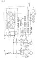
ここで、図1は、本発明に係る水道直結給水システムの実施例を示す全体構成図、図2は、流入圧力(元圧)の各設定圧力を示すグラフ、図3は、ポンプ吐出圧が一定制御方式の一例を示すグラフ、図4は、ポンプ末端圧が一定制御方式の一例を示すグラフ、図5は流入圧力センサ位置から吐出圧センサ位置に到るまでの各器具類の抵抗損失を示すグラフ、図6は、本発明に係る水道直結給水システムの制御回路図、図7,図8は、本発明の実施例の作動を示すフローチャートである。
【0018】
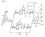
本実施例は、水道本管1に接続された吸込管2から分岐した複数本の流路と、上記流路の各々にそれぞれ設けられたポンプ10,11とポンプ10,11の上流側と下流側でこの流路にそれぞれ設けられた仕切り弁8,9,16,17と、下流側の仕切り弁16,17の下流側で複数本の流路を一つにまとめるよう接続された給水管20と、給水管20に設けられた吐出圧を検知する第1の圧力センサ18及び圧力タンク19と、吸込管2に設けられた流入圧力を検知する第2の圧力センサ7と、複数台のポンプ10,11を制御する制御装置21を備えている。さらに、吸込管2と給水管20とは途中に逆止め弁101を配設したバイパス管102を備えている。
【0019】
この制御装置21は吸込管の流入圧力が吐出側所要圧力に、両圧力センサ間の抵抗を考慮した値より一定時間以上高くなった場合には上記ポンプを停止させ、前記水道本管の圧力が目標圧力以下に低下したら上記ポンプを再始動させるように構成されたものである。さらに、負荷側の給水圧力低下防止のために、前記条件が成立した後、少水量使用状態かどうかを判定し、少水量状態の場合にはポンプを停止させるようにしたものである。
【0020】
また、図6に示すように制御装置21は、ポンプ10,11の速度を制御するインバータ26,27を備え、水道本管の圧力が予め定めた給水制限圧力より低下した場合にはこの圧力を越えて復帰するまで、現在の速度でロックするようにしたものである。
【0021】
以下、詳細に説明する。
図1は本実施例の給水装置の構成を示す。6は汚染防止の逆止め弁(逆流防止)、7はポンプ吸い込み側の吸込管の流入圧力を検出するための第2の圧力センサ、同じく、18は給水管側の圧力を検出するための第1の圧力センサ、8,9,16,17はそれぞれ仕切り弁、14,15は逆止め弁、10,11はそれぞれ電動機12,13によって駆動されるポンプ、102は途中に逆止め弁101を備えたバイパス管であり、前述したように水道本管流入圧力が十分高い流入圧力のみで給水可能な際にはポンプを停止させこのバイパス管を通して給水する。19は内部に空気留りを有する圧力タンク、23,24は少水量使用状態を検出するための流量スイッチである。
【0022】
図6は、本実施例の給水装置の制御装置21の詳細を示し、PWは電源、23は配線用遮断器、24,25はそれぞれ電動機12,13を運転駆動するための電磁接触器のコイルであり、24a,25aはその主回路接点である。また、26,27は前記電動機12,13を運転駆動するためのインバータであり、45,46はインバータの各種設定(例えば、同インバータの運転速度範囲の下限値などの設定)を行うためのコンソール(キー入力装置)である。
【0023】
N1,N2は後でのべるが同インバータの速度を指令する信号であり、28a,29aと同じく運転指令信号であり、これのON時に運転される。また、30はスイッチであり、これを閉じることにより31の安定化電源ユニットが作動し、制御電源が電源端子33に供給され自動運転の準備が完了する。
【0024】
34,35はそれぞれ前記したインバータに速度指令を発するためのD/A変換器などで構成されるインターフェース、36はマイクロコンピューターのCPUであり、37はRAM,ROMから成るメモリであり、38,39,40,41は入出力ポートである。42,43は圧力や速度のデータを設定するためのスイッチである。
【0025】
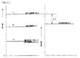
図2は設定データの例を示すもので、流入側圧力の設定値a(最低圧力:ポンプ空転保護停止圧力)、b(給水制限圧力)、c(流入圧力高停止圧力)等を設定してある。尚、流入圧力高停止圧力cは図3を用いた場合にはH0に圧力センサ間の抵抗を加えた値に、図4を用いた場合には、前述のH0の代わりにH4としている。さらに、詳細は後で述べるが図4に示す圧力制御を行う場合の目標値である圧力H1(水量0の点)、H4(水量Qイの点)、前述の流入側圧力の設定値a,b,cなどの値をスイッチ42で設定し、同じく運転速度ND、NAのデータをスイッチ43で設定しそれぞれPIO39,40を介してメモリに読み込む(RAMに格納しておく)。当然ながら、このメモリMのROMには後述の通り、運転制御手順などのプログラムが書き込まれているのは言うまでもない。
【0026】
尚、NDは初期値であり予め設定しているものとする。
また、44は第1及び、第2の圧力センサ7,18の圧力信号をA/D変換して読み込むためのインターフェースであり、同様にして入力ポート41を介してメモリ(RAM)に格納しておく。以上のようにして、制御装置CTLを構成する。
【0027】
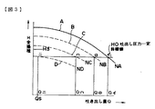
図3は一般的な吐き出し圧力一定制御の場合の運転特性図を示し、縦軸に全揚程H、横軸に水量Qを取って示す。曲線A,B,C,Dは、運転速度は連続であるがそれぞれ、速度をNA(最高速度)NB,NC,ND(最低速度)と仮想した場合のポンプQ−H性能であり、H0はこの際の吐き出し目標圧力である。
【0028】
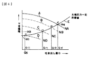
図4は同じく、一般的な末端圧力一定制御方式の場合の運転特性を図示し、図3と同一符号で示すものである。同図に於いて、曲線Eは送水管等の抵抗損失曲線である。この方式では、使用水量がQイ,Qロ,Qハ,Qニと変化すると当然、インバータの運転速度はNA,NB,NC,NDと変化しポンプの運転点は曲線E上をイ,ロ,ハ,ニと変化する。
【0029】
また、図3,図4においてQsは少水量検出センサ23,24の動作流量を示し、これにより少ないと、例えばその接点を閉じ、これにより若干多い水量で接点を開く。
【0030】
通常、ポンプの実揚程に対し配管抵抗が小さいアパート、マンションなどの給水では吐き出し圧力一定制御が使用されることが多い。実揚程に対して配管抵抗が大きい送水管の長い場合には末端圧力一定制御が使用される。これらの方式は給水系最適なものが選定され、前述した運転特性図にしたがって予めプログラミングした運転手順により運転制御される。
【0031】
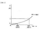
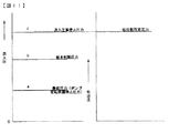
ところで、図1に於いて、ポンプを運転せず、水道本管流入圧力のみで給水することを考えると、逆止め弁,ポンプ,仕切弁,配管類の抵抗損失を考慮せねばならないことは言うまでもない。即ち、吐出側圧力センサ18の元で負荷側の所定圧力(図3ではH0,図4ではH4)を確保すると流入圧力センサ7の所では該センサ18の所で必要な所定圧力に前述の抵抗損失を加えた圧力以上を確保しなければ十分な給水はできない。図5はこの抵抗損失を示したものであり、jは最大使用水量Qイ時の抵抗損失であり、同様にKは過少水量Qsのときの抵抗損失を示している。
【0032】
従来技術で述べたようにもし、流入圧高停止圧力CをH0又はH4と等しく決めていると、流入側圧力がCとなりポンプが停止すると、吐出側圧力センサ18の所ではこの抵抗分だけCより圧力が低下し、ポンプが即始動し、インチングする。あるいは高所負荷側水栓では一時的に給水圧力が低下するのである。
【0033】
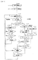
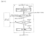
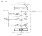
そこで、図7に示すX枠に示すように、流入圧力がC(吐出側所定圧力H0又はH4に抵抗損失Pfを加算した値)以上となって、停止条件が成り立っているか判定して停止させるようにしたものである。詳しく説明するとステップS700で、運転するためのCPUの初期設定を行い、ステップS701で図8に示すタイマ割込処理へジャンプを許可する。ステップS801では圧力センサ7で流入圧力を検出し、結果をメモリSPDATAに格納する。同様にステップS802では圧力センサ18によりポンプ吐出圧力を検出し、メモリDPDATAに格納する。さらに、ステップS803では流量スイッチ23,24の状態をチェックし、結果をメモリに格納し、ステップS804ではポンプ等の故障状態を検出してメモリに格納し、ステップS805ではスイッチ42,43で設定したデータを読み込み、それぞれメモリに格納する。この後、ステップS806で割込処理からステップS702へ戻る。ステップS702では始動条件が確立しているか判定する。
【0034】
例えば図3,図4に於いて、給水圧力(ポンプ吐出圧)がH3以下に下がるとステップS703でポンプを始動し、インバータ周波数がNDとなる信号を出力する。次のステップS704では流入圧力(メモリSPDATAに格納されている)が図2に示すb以上にあるか判定し、これ以上にあればステップS709へジャンプし、そうでない場合には後で詳細に説明するがステップS705へ進む。ステップS709でH4とH1とを比較して、吐出圧力一定制御方式か末端圧力一定制御方式か判定する。H4=H1=H0(図3,図4参照)であれば吐出圧力一定制御方式であり、ステップS714へ進み、そうでなければステップS710へ進み、それぞれの処理を実行する(ステップS710,ステップS714)。
【0035】
ステップS715では吐出圧力一定制御により前述した抵抗損失Pf=j(図5参照)と、末端圧力一定制御ではステップS711でPf=(N)と図2に示すように運転速度Nに基づく抵抗損失を与え、ステップS712では流入圧力(SPDATA)がC(吐出圧力一定制御方式の場合にはH0+j、末端圧力一定制御方式の場合には目標値である曲線E上の圧力にf(N)(Pf=f(N))を加えた値)より高いか確認し、高ければステップS713へ、そうでなければステップS716へ進み、ステップS713では流入圧力がCより高い状態が△t時間継続したか確認し、継続していれば流入圧力のみで十分給水が可能であるから、ステップS717へ進みポンプの停止処理を実行する。ステップS712,713での判定が流入圧力での給水が不可能な場合にはステップS716以降の吐出側による通常の制御を行う。
【0036】
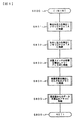
次に、圧力センサ7と18の圧力差が抵抗損失以上となった場合にポンプを停止させる別の実施例を図9により説明する。図9は図7に示すX部を変更したもので、ステップS900で流入圧力(メモリSPDATAに格納されている)と吐出圧(メモリDPDATAに格納されている)の差DELTAPを求め、次のステップS901で前述した抵抗損失Pf以上となっているか判定し、真値であれば図7での説明と同様にステップS902で△t時間この状態が継続しているか判定し、継続していれば流入圧力にて十分給水可能な状態であるからステップS903で、ポンプを停止させ、流入圧力で給水を行う。これ以外については図7の説明と同じであるから説明を省く。
【0037】
以上のようにすれば従来技術で述べた、ポンプがインチングする、一時的に水圧が低下するという問題を解決することが可能である。これらの問題点を解決し、さらに始動頻度を低く改良した実施例を図10により説明する。同図は図7又は図9で示した流入圧力が停止条件を満足した後、水の使用状態が少ないときにポンプを停止させるようにするために、ステップS103をこれらとAND条件で挿入したものである。即ち、ステップS100〜S102は図9の例を使用しており、流入圧力での停止条件が成立した後、ステップS103で流量スイッチが動作しているか判定し、使用量が少なく(通常10〜20l/mm以下)動作していれば次のステップS104でポンプを停止するものである。
【0038】
このようにすればポンプが停止するのは流入圧力のみで給水が可能で且つ、負荷側での水使用が殆どない時であるから、ポンプ始動頻度をさらに低減することが可能となる。
【0039】
さらに、従来技術で述べたように(図11参照)流入圧力によるポンプ停止圧力CをC=j0、C=H4と選んだ場合も図10に示したように、使用水量が極、少ないときのみポンプを停止させて流入圧力で給水するようにすれば前述した従来の問題点を解決することができる。
【0040】
ところで、この水道本管に直結した本給水方式では、他の給水方式と比較して、給水制限時でも直結した給水方式の方が優先的に使用され、不公平であるとの懸念がある。これを対策したものの実施例を図7により説明する。即ち、同図ステップS704での流入圧力がb以下かの判定でb以下と判定されると次のステップS705へ進む(図2参照)。ステップS705では流入圧力がbを越えるまで現状のポンプ運転速度をロックするよう、インバータ(26又は27)の速度指令信号N1又はN2の信号を出力する。さらに、ステップS706以降では流入圧力が図2に示す最低圧力a以下か判定し、そうであればポンプを空転保護のために停止させる。このように給水制限圧力bを予め決めておき、これ以下に流入圧力が下がった場合にはポンプの運転速度を現状速度でロックするため給水が制限され、不公平感が解消する。
【0041】
【発明の効果】
以上説明したように、本発明によれば配水管にかかっている流入圧力が吐出側所定圧力と流入圧力センサから吐出圧センサに到るまでの抵抗損失とを上回った際に、あるいはこの条件と使用水量が少ないという条件とで、流入圧力給水が可能と判断するようにしてあるため、流入圧力の有するエネルギーを利用することができ、省エネルギーとなるばかりでなく、始動頻度が低く、一時的な給水圧低下を未然に防ぐことが可能となり、安定給水ができる。
【0042】
また、受水槽の設置が不要となるので、安全衛生管理やこのための高い人件費等が不要となり、したがって、この水道直結給水システムの維持費を安くすることができるとともに安全衛生上においても問題はない。
【図面の簡単な説明】
【図1】 本発明に係る水道直結給水システムの実施例を示す全体構成図。
【図2】 流入圧力(元圧)の各設定圧力を示すグラフ。
【図3】 ポンプ吐出圧が一定制御方式の一例を示すグラフ。
【図4】 ポンプ末端圧が一定制御方式の一例を示すグラフ。
【図5】 流入圧力センサ位置から吐出圧センサ位置に到るまでの各器具類の抵抗損失を示すグラフ。
【図6】 本発明に係る水道直結給水システムの制御回路図。
【図7】 同上の各実施例の作動を示すフローチャート。
【図8】 同上の各実施例の作動を示すフローチャート。
【図9】 同上の各実施例の作動を示すフローチャート。
【図10】 同上の各実施例の作動を示すフローチャート。
【図11】 流入圧力(元圧)の各設定圧力を示すグラフ。
【符号の説明】
1…水道本管、6,14,15…逆止め弁、7…吸込管2に備わる流入圧力センサ、18…給水管20に備わる吐出圧センサ、10,11…ポンプ、19…圧力タンク、21…制御装置、26,27…インバータ。[0001]
[Industrial application fields]
The present invention relates to a directly connected water supply system for automatically supplying water from a suction pipe connected to a water main to a terminal water faucet.
[0002]
[Prior art]
For example, since the inflow pressure (hydrostatic pressure) is applied to the water in the water distribution pipe (water main) , the goal is that this inflow pressure can supply water to the end hydrant of a two-story building. However, if it becomes a medium- and high-rise building with three or more stories, the inflow pressure alone may be insufficient to supply water to the terminal faucet. Then, the water from a water pipe is once put into a water receiving tank, and water is supplied from this water receiving tank to the terminal water tap of each floor by natural flow from the elevated water tank provided on the roof of the building. Alternatively, the water once put in the water receiving tank is directly supplied to the terminal water faucet by a pressure pump.
[0003]
However, recently, in order to utilize the pressure of the water main and to eliminate unsanitary water receiving tanks, studies have been started to supply water by directly connecting a water supply device to the main. Japanese Patent Application No. 3-30560 (Japanese Patent Laid-Open No. 4-330127) is known as this known example.
[0004]
[Problems to be solved by the invention]
However, the prior art has the following problems.
(1) It is determined whether the distribution pipe inflow pressure upstream from the electric pump is in the range from the minimum pressure to a predetermined pressure or less, and whether the discharge pressure downstream from the pump is equal to a constant pressure, and the pump is operated. Therefore, in actual control, there is a dead band at the predetermined pressure, and even when the load usage is considerably large, the discharge pressure is equal to the predetermined pressure, and when the load water usage is large, start immediately after stopping the pump. Thereafter, starting and stopping are repeated, and the frequency of starting the pump increases, and the motor and its driving means wear and deteriorate. Furthermore, the drive means is an inverter or the like, and its responsiveness is not good as compared with a general direct start-up system, so that the water supply pressure temporarily decreases at the time of start-up.
[0005]
(2) Pressure sensors for detecting the inflow pressure and the discharge pressure are provided, but there is a backflow prevention valve on the suction side to prevent contamination due to backflow from the load side in the directly connected water supply system, especially between pumps and valves. There is a resistor that has a large resistance loss (for example, there are some having a resistance loss of about 10 m in the decompression type), but this resistance loss is taken into consideration. This is also the cause of a momentary drop in the water supply pressure at start-up (1).
[0006]
The object of the present invention is to use this inflow pressure energy when the inflow pressure of the water distribution pipe is sufficient, and further consider the load side use state and the above-described resistance loss when stopping the pump. Is to eliminate the need for installation of the water supply system, to reduce the maintenance cost of the water supply system directly connected to the water supply, and to provide a water supply system directly connected to the water supply that is free from problems in health and safety.
[0007]
[Means for Solving the Problems]
In order to achieve such an object, in the present invention, a water supply pipe for supplying water from a suction pipe connected to a water main pipe to a terminal water faucet, and the end terminal interposed in the middle of the water supply pipe and at least one electric pump to discharge water into the faucet, and a bypass pipe having a check valve connecting the water supply pipe and the suction pipe is disposed from the electric pump to the suction pipe upstream is connected to the water mains An inflow pressure sensor for detecting the inflow pressure of the suction pipe, a water amount detection means for detecting a use state of an excessive water amount on the load side, and a discharge pressure for detecting the discharge pressure. Based on the signal from the sensor and the control means for outputting a signal for operating the electric pump when the detected inflow pressure satisfies the following condition within the range from the minimum pressure to the predetermined pressure or less, Electric pump with variable power Is obtained by a structure in which a driving means for supplying the specified manner.
[0008]
And
(1) A pump stop signal is issued when a value obtained by adding a resistance loss corresponding to the amount of water used between the two sensors is detected with respect to the difference between the detected values of the inflow pressure sensor and the discharge pressure sensor.
[0009]
(2) When the detected value of the inflow pressure sensor is P1, the detected value of the discharge sensor is P2, and the resistance loss according to the amount of water used between the two sensors is Pf, the pump stop signal is satisfied if the condition of P1-P2 ≧ Pf is satisfied. To emit.
[0010]
(3) The conditions under which the excessive water amount detecting means detects the excessive water amount are added to these stop conditions (1) or (2).
[0011]
(4) When the discharge pressure and the inflow pressure are equal, the stop water signal is generated when the water shortage detecting means detects the water shortage.
[0012]
That is, the pump is started when both the inflow pressure start condition and the discharge pressure start condition are satisfied, and the pump is stopped when both the inflow pressure stop condition and the discharge pressure stop condition are satisfied.
[0013]
[Action]
Results 1) The control means detects the inflow pressure, the inlet pressure is determined whether resistive losses added value over the plumbing fixtures from the inflow pressure sensor and the discharge-side predetermined pressure up to the discharge pressure sensor, it determines If it is more than that, a signal to stop the pump is issued.
[0014]
2) the control means detects the inflow pressure and the discharge pressure, the differential pressure between the inlet pressure and the discharge pressure is determined whether or resistive losses of the plumbing fixtures therebetween, the judgment result is stop the pump if more A signal to be issued.
[0015]
3) Further, after the stop condition due to the inflow pressure of 1) and 2) is satisfied, the operation of the flow switch is determined, and a stop signal is issued when the amount of water used is small.
[0016]
4) When the inflow pressure sensor detects the water supply limit pressure, a signal that locks at the current pump operation speed is output to the inverter until the inflow pressure exceeds this pressure .
[0017]
【Example】
Embodiments of the present invention will be described below with reference to FIGS.
A first embodiment of the present invention will be described with reference to FIGS.
Here, FIG. 1 is an overall configuration diagram showing an embodiment of a direct water supply system for water supply according to the present invention, FIG. 2 is a graph showing each set pressure of an inflow pressure (original pressure), and FIG. FIG. 4 is a graph showing an example of the constant control method, FIG. 4 is a graph showing an example of the pump end pressure control method, and FIG. 5 shows the resistance loss of each instrument from the inflow pressure sensor position to the discharge pressure sensor position. FIG. 6 is a control circuit diagram of the direct water supply system according to the present invention, and FIGS. 7 and 8 are flowcharts showing the operation of the embodiment of the present invention.
[0018]
In this embodiment, a plurality of flow paths branched from a
[0019]
This
[0020]
The control device as shown in FIG. 6. 21, an
[0021]
This will be described in detail below.
FIG. 1 shows the configuration of the water supply apparatus of this embodiment. Check valve 6 pollution (backflow prevention), second pressure sensor for detecting the inflow pressure of the suction line of the
[0022]
FIG. 6 shows the details of the
[0023]
N1 and N2 are signals for instructing the speed of the inverter as will be described later, and are operation command signals similar to 28a and 29a.
[0024]
[0025]
FIG. 2 shows an example of setting data. Set values a (minimum pressure: pump idling protection stop pressure), b (water supply restriction pressure), c (inflow pressure high stop pressure), etc. is there. The inflow pressure high stop pressure c is a value obtained by adding a resistance between pressure sensors to H0 when FIG. 3 is used, and is H4 instead of the above-described H0 when FIG. 4 is used. Further details are described below the pressure which is a target value for performing pressure control shown in FIG. 4 H1 (point water 0), H4 (point water Q i), the set value a of the inflow side pressure mentioned above, Values such as b and c are set by the switch 42, and data of the operation speeds ND and NA are similarly set by the switch 43 and read into the memory via the PIOs 39 and 40 (stored in the RAM). Of course, it goes without saying that a program such as an operation control procedure is written in the ROM of the memory M as described later.
[0026]
Note that ND is an initial value and is set in advance.
Reference numeral 44 denotes an interface for A / D-converting and reading the pressure signals of the first and
[0027]
FIG. 3 shows an operation characteristic diagram in the case of general discharge pressure constant control, in which the vertical axis indicates the total head H and the horizontal axis indicates the amount of water Q. Curves A, B, C, and D are pump Q-H performances when the operation speed is continuous but the speeds are assumed to be NA (maximum speed) NB, NC, and ND (minimum speed), respectively. This is the discharge target pressure at this time.
[0028]
FIG. 4 similarly shows the operating characteristics in the case of a general terminal pressure constant control method, and is indicated by the same reference numerals as in FIG. In the figure, a curve E is a resistance loss curve of a water pipe or the like. In this system, when the amount of water used changes Q, Q, Q, Q, the driving speed of the inverter changes to NA, NB, NC, ND, and the operating point of the pump moves on the curve E. , C, change.
[0029]
3 and 4, Qs indicates the operation flow rate of the small water
[0030]
Normally, constant discharge pressure control is often used for water supply in apartments and condominiums where the pipe resistance is small relative to the actual pump head. When the water pipe has a long pipe resistance with respect to the actual head, the terminal pressure constant control is used. These systems are selected to be optimal for the water supply system, and the operation is controlled according to the operation procedure programmed in advance according to the operation characteristic diagram described above.
[0031]
By the way, in FIG. 1, it is needless to say that the resistance loss of the check valve, the pump, the gate valve, and the piping must be taken into consideration when supplying water only with the water mains inlet pressure without operating the pump. Yes. That is, when a predetermined pressure on the load side (H0 in FIG. 3 and H4 in FIG. 4) is secured under the discharge-side pressure sensor 18, the above-mentioned resistance is applied to the predetermined pressure required at the sensor 18 at the
[0032]
As described in the prior art, if the inflow pressure high stop pressure C is determined to be equal to H0 or H4, when the inflow side pressure becomes C and the pump stops, the discharge side pressure sensor 18 is equivalent to this resistance. The pressure drops further and the pump starts immediately and inches. Alternatively, the water supply pressure temporarily decreases at the high load tap.
[0033]
Therefore, as shown in the X frame shown in FIG. 7, the inflow pressure becomes C (the value obtained by adding the resistance loss Pf to the discharge side predetermined pressure H0 or H4) or more, and it is determined whether the stop condition is satisfied, and the stop is made. It is what I did. More specifically, in step S700, the CPU is initialized for operation, and in step S701, jumping to the timer interrupt process shown in FIG. 8 is permitted. In step S801, the inflow pressure is detected by the
[0034]
For example, in FIGS. 3 and 4, when the feed water pressure (pump discharge pressure) falls below H3, the pump is started in step S703, and a signal with an inverter frequency of ND is output. In the next step S704, it is determined whether or not the inflow pressure (stored in the memory SPDATA) is not less than b shown in FIG. 2, and if it is more than that, the process jumps to step S709, and if not, will be described in detail later. However, the process proceeds to step S705. In step S709, H4 and H1 are compared to determine whether the discharge pressure constant control method or the terminal pressure constant control method. If H4 = H1 = H0 (see FIGS. 3 and 4), the control is a constant discharge pressure control method, and the process proceeds to step S714. Otherwise, the process proceeds to step S710 and the respective processes are executed (step S710, step S714). ).
[0035]
In step S715, the above-described resistance loss Pf = j (see FIG. 5) by the discharge pressure constant control, and in the terminal pressure constant control, the resistance loss based on the operation speed N as shown in FIG. In step S712, the inflow pressure (SPDATA) is C (H0 + j in the case of the constant discharge pressure control method, and f (N) (Pf = Pf = f (N)) is added or higher), and if it is higher, the process proceeds to step S713, and if not, the process proceeds to step S716. In step S713, it is confirmed whether the state where the inflow pressure is higher than C continues for Δt time. If it continues, sufficient water supply is possible with only the inflow pressure , and the process proceeds to step S717 to stop the pump. When the determination in steps S712 and 713 is that water supply at the inflow pressure is impossible, normal control on the discharge side after step S716 is performed.
[0036]
Next, another embodiment for stopping the pump when the pressure difference between the
[0037]
By doing so, it is possible to solve the problems described in the prior art that the pump is inched and the water pressure temporarily decreases. An embodiment in which these problems are solved and the starting frequency is further lowered will be described with reference to FIG. In the figure, after the inflow pressure shown in FIG. 7 or FIG. 9 satisfies the stop condition, step S103 is inserted under these AND conditions in order to stop the pump when the water usage is low. It is. That is, steps S100 to S102 use the example of FIG. 9, and after the stop condition at the inflow pressure is established, it is determined whether the flow rate switch is operating in step S103, and the usage amount is small (usually 10 to 20 l). / Mm or less) If it is operating, the pump is stopped in the next step S104.
[0038]
In this way, the pump is stopped when water can be supplied only by the inflow pressure and there is almost no water use on the load side, so that the pump start frequency can be further reduced.
[0039]
Further, as described in the prior art (see FIG. 11), when the pump stop pressure C due to the inflow pressure is selected as C = j0 and C = H4, as shown in FIG. 10, only when the amount of water used is extremely small. If the pump is stopped and water is supplied at the inflow pressure , the conventional problems described above can be solved.
[0040]
By the way, in the present water supply system which is directly connected to the water this tube, as compared with other water supply system, towards the water supply system which is directly connected even when water restrictions are used preferentially, there is a concern that it is unfair. An embodiment of this countermeasure will be described with reference to FIG. That is, if it is determined that the inflow pressure in step S704 is equal to or less than b in step S704 , the process proceeds to next step S705 (see FIG. 2). As the step S705 in the inflow pressure to lock the pump operating speed of current to over b, to output the signal of the speed command signal N1 or N2 of the inverter (26 or 27). Further, after step S706, it is determined whether the inflow pressure is lower than the minimum pressure a shown in FIG. 2, and if so, the pump is stopped for idling protection. In this way, the water supply limit pressure b is determined in advance, and when the inflow pressure falls below this, the pump operation speed is locked at the current speed, so that the water supply is limited and the unfairness is eliminated.
[0041]
【The invention's effect】
As described above, according to the present invention, when the inflow pressure applied to the water distribution pipe exceeds the discharge-side predetermined pressure and the resistance loss from the inflow pressure sensor to the discharge pressure sensor, or under this condition, Since it is determined that inflow pressure water supply is possible under the condition that the amount of water used is small, not only can the energy of the inflow pressure be used, it is possible to save energy, but also the start-up frequency is low and temporary It is possible to prevent a decrease in the water supply pressure, and a stable water supply can be achieved.
[0042]
In addition, since installation of a water receiving tank is not required, safety and hygiene management and high labor costs for this are unnecessary, so that it is possible to reduce the maintenance cost of the water supply system directly connected to the water supply, and there is a problem in terms of safety and health. There is no.
[Brief description of the drawings]
FIG. 1 is an overall configuration diagram showing an embodiment of a direct water supply system for water supply according to the present invention.
FIG. 2 is a graph showing each set pressure of inflow pressure (source pressure).
FIG. 3 is a graph showing an example of a control method in which the pump discharge pressure is constant.
FIG. 4 is a graph showing an example of a control method in which the pump end pressure is constant.
FIG. 5 is a graph showing resistance loss of each instrument from the inflow pressure sensor position to the discharge pressure sensor position.
FIG. 6 is a control circuit diagram of a direct water supply system for water supply according to the present invention.
FIG. 7 is a flowchart showing the operation of each embodiment described above.
FIG. 8 is a flowchart showing the operation of each embodiment described above.
FIG. 9 is a flowchart showing the operation of each embodiment described above.
FIG. 10 is a flowchart showing the operation of each embodiment described above.
FIG. 11 is a graph showing each set pressure of inflow pressure (source pressure).
[Explanation of symbols]
DESCRIPTION OF
Claims (5)
この電動ポンプより上流側の吸込管に配設され水道本管に接続された吸込管の流入圧力を検知する流入圧力センサと、前記電動ポンプより下流側の給水管に配設され過少水量を検知する過少水量検出手段と吐出圧を検知する吐出圧センサと、検知された流入圧力が吐出側所要圧力と前記両圧力センサ間の予め設定された所定の抵抗を加算した値以上となり、前記過少水量検知手段が過少水量状態を検出したときにポンプを停止して、水道本管に接続された吸込管が直接給水し、検知された吐出圧力が所定の始動圧力以下に下がったときに始動させるための信号を出力する制御手段と、この制御手段からの信号に基づいて可変電力を前記電動ポンプに指定して供給する駆動手段とを備えたことを特徴とする水道直結給水システム。 A water supply pipe for supplying water from the suction pipe connected to the water main pipe to the terminal water tap, at least one electric pump interposed in the middle of the water supply pipe and discharging water to the terminal water tap, and a suction pipe; A bypass pipe having a check valve connecting the water supply pipe;
An inlet pressure sensor for detecting the flow pressure of the upstream side suction pipe which is connected to the water main placed on the suction pipe than the electric pump, the under-water is disposed to the water supply pipe downstream of the electric pump sensing to the discharge pressure sensor for detecting the under-water detecting means and the ejection discharge pressure becomes a sensed inflow pressure discharge side required pressure to the higher preset value obtained by adding a predetermined resistance between the two pressure sensors, the under- The pump is stopped when the water amount detection means detects an underwater state, and the suction pipe connected to the main water pipe supplies water directly, and starts when the detected discharge pressure falls below a predetermined starting pressure. A water supply system directly connected to a water supply, comprising: a control means for outputting a signal for the operation; and a drive means for specifying and supplying variable electric power to the electric pump based on a signal from the control means.
Priority Applications (1)
| Application Number | Priority Date | Filing Date | Title |
|---|---|---|---|
| JP05832498A JP3649897B2 (en) | 1998-03-10 | 1998-03-10 | Direct water supply system |
Applications Claiming Priority (1)
| Application Number | Priority Date | Filing Date | Title |
|---|---|---|---|
| JP05832498A JP3649897B2 (en) | 1998-03-10 | 1998-03-10 | Direct water supply system |
Related Parent Applications (1)
| Application Number | Title | Priority Date | Filing Date |
|---|---|---|---|
| JP13651895A Division JP3287528B2 (en) | 1995-06-02 | 1995-06-02 | Water supply device |
Publications (2)
| Publication Number | Publication Date |
|---|---|
| JPH10259622A JPH10259622A (en) | 1998-09-29 |
| JP3649897B2 true JP3649897B2 (en) | 2005-05-18 |
Family
ID=13081119
Family Applications (1)
| Application Number | Title | Priority Date | Filing Date |
|---|---|---|---|
| JP05832498A Expired - Fee Related JP3649897B2 (en) | 1998-03-10 | 1998-03-10 | Direct water supply system |
Country Status (1)
| Country | Link |
|---|---|
| JP (1) | JP3649897B2 (en) |
Families Citing this family (8)
| Publication number | Priority date | Publication date | Assignee | Title |
|---|---|---|---|---|
| CN100336986C (en) * | 2005-07-28 | 2007-09-12 | 济南普利龙供水设备有限公司 | Technique of automatic water supply through forced suppression without suction lift |
| JP5147748B2 (en) * | 2009-01-30 | 2013-02-20 | 株式会社日立産機システム | Booster water supply system |
| CN102852189A (en) * | 2011-06-30 | 2013-01-02 | 杨丽萍 | Totally closed negative-pressure-free additive pressure water supply device |
| CN103046616A (en) * | 2012-12-26 | 2013-04-17 | 淮安万邦香料工业有限公司 | Constant-pressure control method for circulating water system |
| CN103924635A (en) * | 2013-01-15 | 2014-07-16 | 上海格澜富特机械科技有限公司 | Novel non-negative pressure water supply device |
| CN104153426A (en) * | 2014-08-19 | 2014-11-19 | 安徽金科橡塑制品有限公司 | Energy-saving water supply system |
| CN105155626A (en) * | 2015-09-01 | 2015-12-16 | 樊启 | Non-negative-pressure automatic variable-frequency water supply device |
| CN109056906B (en) * | 2018-09-18 | 2023-11-24 | 李立芳 | Single-pump full-automatic water supply system and water supply method thereof |
-
1998
- 1998-03-10 JP JP05832498A patent/JP3649897B2/en not_active Expired - Fee Related
Also Published As
| Publication number | Publication date |
|---|---|
| JPH10259622A (en) | 1998-09-29 |
Similar Documents
| Publication | Publication Date | Title |
|---|---|---|
| JP6184792B2 (en) | Water supply equipment | |
| JP3287528B2 (en) | Water supply device | |
| EP2137413A1 (en) | Sewage pump blockage detection | |
| JP3373494B2 (en) | Water supply system | |
| JP3649897B2 (en) | Direct water supply system | |
| KR101992765B1 (en) | Hybrid water supply system of backdraft prevention and control method thereof | |
| JP5147748B2 (en) | Booster water supply system | |
| JP3567060B2 (en) | Water supply device for water supply with water storage tank | |
| JP2021063499A (en) | Hydraulic power generation system | |
| JP5022389B2 (en) | Booster water supply system | |
| AU2003262296B2 (en) | Rainwater harvesting | |
| JP3225222B2 (en) | Water supply device and its pump control method | |
| JP2923265B2 (en) | Water supply device and its pump control method | |
| JP2923250B2 (en) | Water supply device and its pump control method | |
| JPH04330127A (en) | Automatic water supply system | |
| JP2923249B2 (en) | Water supply system | |
| AU2005100775C4 (en) | Rainwater Harvesting | |
| JPH05240186A (en) | Water supply device | |
| JPH08144960A (en) | Pump device | |
| JPS6122157B2 (en) | ||
| JP5455384B2 (en) | Increased pressure water supply system for medium to high-rise buildings | |
| JPH11315789A (en) | Water supply device and its pump control method | |
| JP2026047581A (en) | Communication device | |
| JPH0819915B2 (en) | Variable speed pump operating device | |
| JPS6319380Y2 (en) |
Legal Events
| Date | Code | Title | Description |
|---|---|---|---|
| A131 | Notification of reasons for refusal |
Free format text: JAPANESE INTERMEDIATE CODE: A131 Effective date: 20041019 |
|
| A521 | Written amendment |
Free format text: JAPANESE INTERMEDIATE CODE: A523 Effective date: 20041217 |
|
| TRDD | Decision of grant or rejection written | ||
| A01 | Written decision to grant a patent or to grant a registration (utility model) |
Free format text: JAPANESE INTERMEDIATE CODE: A01 Effective date: 20050208 |
|
| A61 | First payment of annual fees (during grant procedure) |
Free format text: JAPANESE INTERMEDIATE CODE: A61 Effective date: 20050216 |
|
| R150 | Certificate of patent or registration of utility model |
Free format text: JAPANESE INTERMEDIATE CODE: R150 |
|
| FPAY | Renewal fee payment (event date is renewal date of database) |
Free format text: PAYMENT UNTIL: 20080225 Year of fee payment: 3 |
|
| FPAY | Renewal fee payment (event date is renewal date of database) |
Free format text: PAYMENT UNTIL: 20090225 Year of fee payment: 4 |
|
| FPAY | Renewal fee payment (event date is renewal date of database) |
Free format text: PAYMENT UNTIL: 20090225 Year of fee payment: 4 |
|
| FPAY | Renewal fee payment (event date is renewal date of database) |
Free format text: PAYMENT UNTIL: 20100225 Year of fee payment: 5 |
|
| FPAY | Renewal fee payment (event date is renewal date of database) |
Free format text: PAYMENT UNTIL: 20100225 Year of fee payment: 5 |
|
| FPAY | Renewal fee payment (event date is renewal date of database) |
Free format text: PAYMENT UNTIL: 20110225 Year of fee payment: 6 |
|
| FPAY | Renewal fee payment (event date is renewal date of database) |
Free format text: PAYMENT UNTIL: 20120225 Year of fee payment: 7 |
|
| FPAY | Renewal fee payment (event date is renewal date of database) |
Free format text: PAYMENT UNTIL: 20120225 Year of fee payment: 7 |
|
| FPAY | Renewal fee payment (event date is renewal date of database) |
Free format text: PAYMENT UNTIL: 20130225 Year of fee payment: 8 |
|
| FPAY | Renewal fee payment (event date is renewal date of database) |
Free format text: PAYMENT UNTIL: 20130225 Year of fee payment: 8 |
|
| FPAY | Renewal fee payment (event date is renewal date of database) |
Free format text: PAYMENT UNTIL: 20140225 Year of fee payment: 9 |
|
| LAPS | Cancellation because of no payment of annual fees |