JP3649876B2 - Cylindrical secondary battery - Google Patents
Cylindrical secondary battery Download PDFInfo
- Publication number
- JP3649876B2 JP3649876B2 JP26617397A JP26617397A JP3649876B2 JP 3649876 B2 JP3649876 B2 JP 3649876B2 JP 26617397 A JP26617397 A JP 26617397A JP 26617397 A JP26617397 A JP 26617397A JP 3649876 B2 JP3649876 B2 JP 3649876B2
- Authority
- JP
- Japan
- Prior art keywords
- negative electrode
- electrode plate
- positive
- positive electrode
- battery
- Prior art date
- Legal status (The legal status is an assumption and is not a legal conclusion. Google has not performed a legal analysis and makes no representation as to the accuracy of the status listed.)
- Expired - Fee Related
Links
- 238000004804 winding Methods 0.000 claims description 58
- 239000007774 positive electrode material Substances 0.000 claims description 7
- 239000007773 negative electrode material Substances 0.000 claims description 4
- 230000008878 coupling Effects 0.000 claims 1
- 238000010168 coupling process Methods 0.000 claims 1
- 238000005859 coupling reaction Methods 0.000 claims 1
- XEEYBQQBJWHFJM-UHFFFAOYSA-N Iron Chemical compound [Fe] XEEYBQQBJWHFJM-UHFFFAOYSA-N 0.000 description 8
- PXHVJJICTQNCMI-UHFFFAOYSA-N Nickel Chemical compound [Ni] PXHVJJICTQNCMI-UHFFFAOYSA-N 0.000 description 8
- 230000000694 effects Effects 0.000 description 8
- 238000003466 welding Methods 0.000 description 8
- 230000000052 comparative effect Effects 0.000 description 7
- 229910052739 hydrogen Inorganic materials 0.000 description 4
- 239000001257 hydrogen Substances 0.000 description 4
- 229910052742 iron Inorganic materials 0.000 description 4
- 238000004519 manufacturing process Methods 0.000 description 4
- 229910052759 nickel Inorganic materials 0.000 description 4
- 239000010935 stainless steel Substances 0.000 description 4
- 229910001220 stainless steel Inorganic materials 0.000 description 4
- 238000003860 storage Methods 0.000 description 4
- 238000004132 cross linking Methods 0.000 description 3
- 230000002093 peripheral effect Effects 0.000 description 3
- RYGMFSIKBFXOCR-UHFFFAOYSA-N Copper Chemical compound [Cu] RYGMFSIKBFXOCR-UHFFFAOYSA-N 0.000 description 2
- UFHFLCQGNIYNRP-UHFFFAOYSA-N Hydrogen Chemical compound [H][H] UFHFLCQGNIYNRP-UHFFFAOYSA-N 0.000 description 2
- WHXSMMKQMYFTQS-UHFFFAOYSA-N Lithium Chemical compound [Li] WHXSMMKQMYFTQS-UHFFFAOYSA-N 0.000 description 2
- HBBGRARXTFLTSG-UHFFFAOYSA-N Lithium ion Chemical compound [Li+] HBBGRARXTFLTSG-UHFFFAOYSA-N 0.000 description 2
- 239000011149 active material Substances 0.000 description 2
- 229910045601 alloy Inorganic materials 0.000 description 2
- 239000000956 alloy Substances 0.000 description 2
- XAGFODPZIPBFFR-UHFFFAOYSA-N aluminium Chemical compound [Al] XAGFODPZIPBFFR-UHFFFAOYSA-N 0.000 description 2
- 229910052782 aluminium Inorganic materials 0.000 description 2
- 229910052802 copper Inorganic materials 0.000 description 2
- 239000010949 copper Substances 0.000 description 2
- 238000010586 diagram Methods 0.000 description 2
- 238000002474 experimental method Methods 0.000 description 2
- 229910052744 lithium Inorganic materials 0.000 description 2
- 229910001416 lithium ion Inorganic materials 0.000 description 2
- -1 polyethylene Polymers 0.000 description 2
- 229910012851 LiCoO 2 Inorganic materials 0.000 description 1
- 229910015643 LiMn 2 O 4 Inorganic materials 0.000 description 1
- 229910013290 LiNiO 2 Inorganic materials 0.000 description 1
- 239000004698 Polyethylene Substances 0.000 description 1
- 239000004743 Polypropylene Substances 0.000 description 1
- PLLZRTNVEXYBNA-UHFFFAOYSA-L cadmium hydroxide Chemical compound [OH-].[OH-].[Cd+2] PLLZRTNVEXYBNA-UHFFFAOYSA-L 0.000 description 1
- 239000003575 carbonaceous material Substances 0.000 description 1
- 230000001771 impaired effect Effects 0.000 description 1
- 239000000463 material Substances 0.000 description 1
- 229910021382 natural graphite Inorganic materials 0.000 description 1
- BFDHFSHZJLFAMC-UHFFFAOYSA-L nickel(ii) hydroxide Chemical compound [OH-].[OH-].[Ni+2] BFDHFSHZJLFAMC-UHFFFAOYSA-L 0.000 description 1
- 229920000573 polyethylene Polymers 0.000 description 1
- 229920001155 polypropylene Polymers 0.000 description 1
- 238000000926 separation method Methods 0.000 description 1
Images
Classifications
-
- Y—GENERAL TAGGING OF NEW TECHNOLOGICAL DEVELOPMENTS; GENERAL TAGGING OF CROSS-SECTIONAL TECHNOLOGIES SPANNING OVER SEVERAL SECTIONS OF THE IPC; TECHNICAL SUBJECTS COVERED BY FORMER USPC CROSS-REFERENCE ART COLLECTIONS [XRACs] AND DIGESTS
- Y02—TECHNOLOGIES OR APPLICATIONS FOR MITIGATION OR ADAPTATION AGAINST CLIMATE CHANGE
- Y02E—REDUCTION OF GREENHOUSE GAS [GHG] EMISSIONS, RELATED TO ENERGY GENERATION, TRANSMISSION OR DISTRIBUTION
- Y02E60/00—Enabling technologies; Technologies with a potential or indirect contribution to GHG emissions mitigation
- Y02E60/10—Energy storage using batteries
-
- Y—GENERAL TAGGING OF NEW TECHNOLOGICAL DEVELOPMENTS; GENERAL TAGGING OF CROSS-SECTIONAL TECHNOLOGIES SPANNING OVER SEVERAL SECTIONS OF THE IPC; TECHNICAL SUBJECTS COVERED BY FORMER USPC CROSS-REFERENCE ART COLLECTIONS [XRACs] AND DIGESTS
- Y02—TECHNOLOGIES OR APPLICATIONS FOR MITIGATION OR ADAPTATION AGAINST CLIMATE CHANGE
- Y02P—CLIMATE CHANGE MITIGATION TECHNOLOGIES IN THE PRODUCTION OR PROCESSING OF GOODS
- Y02P70/00—Climate change mitigation technologies in the production process for final industrial or consumer products
- Y02P70/50—Manufacturing or production processes characterised by the final manufactured product
Landscapes
- Secondary Cells (AREA)
- Connection Of Batteries Or Terminals (AREA)
Description
【0001】
【発明の属する技術分野】
本発明は、円筒型二次電池に関し、詳しくは円筒型二次電池の電極構造に関する。
【0002】
【従来の技術】
近年、大出力を要する電気自動車の駆動電源や電力貯蔵用の媒体としての利用を図るため、電池の大型化が図られつつある。そのため、電極面積が大きくなり、それに応じて円筒型二次電池にあっては、渦巻き電極体の製造工程において、正・負極板の巻回回数が大きくなり、正・負極板の巻き取り時間の増大が問題とされている。
【0003】
ところで、この種の円筒型二次電池の典型的な渦巻き電極体は、特公昭和59−10536号公報に示すように、一枚の正極板と一枚の負極板を、セパレータを介して重ね合わせて巻回した構造である。このような構造の電池では、大出力の大型の円筒型二次電池に適用すると、正・負極板の巻回回数が大きくなり、巻き取りの高速化を図れない。
【0004】
そこで、かかる課題を解決するため、特公昭和61−31594号公報に示す円筒型二次電池が提案されている。この特公昭和61−31594号公報に示す円筒型二次電池では、各一枚の正・負極板を幅方向にU字状に折り曲げ、これら正・負極板を相互にかみ合い状態に組み合わせ、この状態で渦巻き状に巻回して渦巻き電極体の製造を行っている。従って、特公昭和59−10536号公報に示すような、一枚の正極板と一枚の負極板を重ね合わせて巻回した場合に比べて、巻回回数が半分になり、正・負極板の巻き取りの高速化が図れる。
【0005】
【発明が解決しようとする課題】
しかしながら、上記従来の円筒型二次電池では、U字状に折り曲げた正・負極板を巻き取る構造のため、例えば電池径が2cm以上となると、正・負極板を巻き取る際に正・負極板に引っ張り応力が発生して巻きずれが生じ、精度良く巻き取ることが困難となる。また、無理に力をかけて巻き取ると、正・負極板に部分的な歪みが生じ、その部分で活物質が剥離してしまう。
【0006】
本発明は、上記課題に鑑みてなされたものであり、電池径が小さいものから大きいものまで広範囲の電池径の電池において、正・負極板を、巻きずれがなく精度良く巻き取ることができ、しかも巻回回数の低減による正・負極板の巻き取りの高速化を図ることができる円筒型二次電池を提供することを目的とする。
【0007】
【課題を解決するための手段】
上記目的を達成するために、本発明の円筒型二次電池は、帯状の正極集電体の両面に正極活物質層が形成された正極板と、帯状の負極集電体の両面に負極活物質層が形成された負極板とが、帯状のセパレータを介して渦巻き状に巻回される渦巻き電極体を備えた円筒型二次電池において、前記渦巻き電極体は、各複数枚の正極板と負極板を、セパレータを介して正極板と負極板が交互になるように重ね合わせて巻回された構造とされていることを特徴とする。
【0008】
上記構成によれば、複数枚の正極板と負極板を重ね合わせて巻回しているので、巻回回数が低減され、正・負極板の巻き取りの高速化が図れる。この結果、生産性が向上する。特に、巻回回数の大きい大型電池において、この効果は顕著である。また、電池径が大きい場合でも、従来の円筒型二次電池(特公昭和61−31594号公報記載の電池)のように巻きずれの発生や、活物質が剥離してしまうという問題も解消され、正・負極板を巻きずれがなく精度良く巻き取ることができる。尚、集電体の厚みの薄い例えばリチウムイオン電池等のような径の小さい電池に本発明を適用しても、巻回回数が低減され、さらに巻きずれがなく精度良く巻き取ることができることは勿論である。
【0009】
本発明の第2の態様は、上記本発明円筒型二次電池において、渦巻き電極体を構成する各複数枚の正極板と負極板のうちの少なくとも一方の極板が、巻き初め端部で固定されていることを特徴とする。
【0010】
このように巻き初め端部で固定されていれば、正・負極板の巻き取りを、さらに円滑に行うことができる。また、巻き初め端部で、一方の極が他方の極に包み込まれた状態となるため、その部分において対極面積が増大し、電極の利用効率が向上する。
【0011】
本発明の第3の態様は、帯状の正極集電体の両面に正極活物質層が形成された正極板と、帯状の負極集電体の両面に負極活物質層が形成された負極板とが、帯状のセパレータを介して渦巻き状に巻回される渦巻き電極体を備えた円筒型二次電池において、前記渦巻き電極体は、正極板と負極板が、それぞれその長手方向に折り曲げられ、セパレータを介して互いに噛み合い状態に組合わされ、この組合わされた状態で巻回された構造とされていることを特徴とする。
【0012】
上記構成によれば、上記第2の態様にかかる発明の作用効果に加えて、渦巻き電極体の巻き終わり部分においても、一方の極板が他方の極板に包み込まれた状態となるため、対極面積がそれだけ増加し、電極の利用効率を大きくすることができる。
【0013】
本発明の第4の態様は、上記第1乃至第3の態様のいずれかの円筒型二次電池において、前記渦巻き電極体の高さ方向一端部側においては、正極板及びセパレータが、負極板より突出形成され、渦巻き電極体の高さ方向他端部側においては、負極板及びセパレータが、正極板より突出形成され、さらに、前記高さ方向一端部側において集電タブが設けられており、この集電タブは、負極板を介して対向する正極板の内側周回部分と外側周回部分の各端部間に架け渡された架橋部と、一端が架橋部に連なり他端が外部端子に接続されている連結部とを有することを特徴とする。
【0014】
上記構成によれば、1個の集電タブにより正極板の2ヵ所から集電を行うことが可能となり、集電効果が向上する。また、渦巻き電極体の高さ方向一端部側においては、正極板及びセパレータが負極板より突出形成されているので、集電タブと負極板とが短絡することが防がれる。
【0015】
本発明の第5の態様は、上記第4の態様の円筒型二次電池において、前記集電タブは正・負極板の巻き取り前に設けられていることを特徴とする。
【0016】
上記構成によれば、正・負極板の巻き取りの際に、極板間の巻きずれがなく、正・負極板の巻き取りを円滑に行うことができ、その結果、作業性を改善することができる。
【0017】
本発明の第6の態様は、上記第2乃至第5の態様のいずれかの円筒型二次電池において、前記渦巻き電極体は、巻き始めが正極で、巻き終わりが負極となるように巻回されていることを特徴とする。
【0018】
巻き始めが正極で巻き終わりが負極の構成に加えて、上記第2又は第3の態様にかかる構成を組み合わせることにより、正極支配の電池において、巻き始め端部と巻き終り端部における正極の利用効率が向上する。
【0019】
本発明の第7の態様は、上記第1乃至第6の態様のいずれかの円筒型二次電池において、前記渦巻き電極体の最外周が負極であることを特徴とする。
【0020】
上記構成によれば、渦巻き型電極体の最外周が負極であるので、電池缶の側面から負極側の集電が可能となる。
【0021】
【発明の実施の形態】
(第1実施形態)
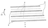
本発明の第1実施形態を、図1〜図8に基づいて、以下に説明する。尚、図2、図3、図4及び図8においては、理解の容易のため、セパレータを破線で示している。
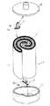
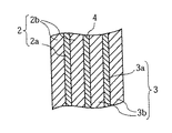
図1は本発明に係る円筒型二次電池の主要部分の構造を示す分解斜視図である。この図1においては、理解の容易のため、セパレータは省略されている。渦巻き電極体1は、正極板2と負極板3とがセパレータ4(図2、図3を参照)を介して渦巻き状に巻回された構造とされている。正極板2は、図5に明らかに示すように、帯状の正極集電体2aの両面に正極活物質層2bが形成された構成とされ、負極板3は、帯状の負極集電体3aの両面に負極活物質層3bが形成された構成とされている。尚、電極体1は、図面上は2回程度巻回されたものが示されているが、これは理解の容易のためであり、巻回回数は特に限定されるものではない。
【0022】
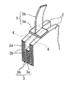
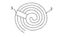
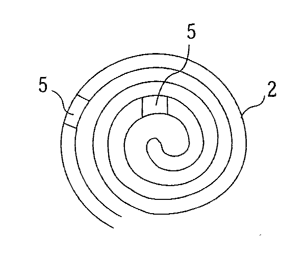
渦巻き電極体1の高さ方向上端部側には、正極集電タブ5が設けられており、渦巻き電極体1の高さ方向下端部側には、負極集電タブ6が設けられている。正極集電タブ5は、図2及び図4にも示すように、負極板3及びセパレータ4を介して対向する正極板2の外側周回部分と内側周回部分間に架け渡された架橋部5aと、架橋部5aに一体的に形成されている連結部5bとから成る。負極集電タブ6も、正極集電タブ5と同様に正極板2及びセパレータ4を介して対向する負極板3の外側周回部分と内側周回部分間に架け渡された架橋部6aと、架橋部6aに一体的に形成されている連結部6bとから成る。架橋部5a,6aと正・負極板2,3の各端部とは、スポット溶接により溶着されている。また、正極集電タブ5においては、連結部5bの先端が電池缶蓋10にスポット溶接により溶着されており、負極集電タブ6においては、連結部6bの先端が電池缶の底面11にスポット溶接により溶着されている。この集電タブ5,6は、正・負極板2,3の巻き取り前に正・負極板2,3に溶着されている。従って、後述するように、正・負極板2,3の巻き取りを円滑に行うことができる。更に、このように集電タブを設けることにより、各極板の外側周回部分と内側周回部の2カ所から集電可能となる。
【0023】
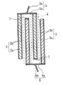
また、渦巻き電極体1の高さ方向上端部側においては、図4に示すように、正極板2及びセパレータ4の各上端部が、負極板3の上端部より上方に突出形成され、渦巻き電極体1の高さ方向下端部側においては、負極板3びセパレータ4の各下端部が、正極板2の下端部より下方に突出形成されている。更に、正極集電タブ5に対向する負極板の上面、及び負極集電タブ6に対向する正極板の下面には、それぞれ絶縁層7が形成されている。このような正・負極板の段差構造及び正・負極板端面の絶縁構造により、正極集電タブ5と負極板3の短絡、並びに負極集電タブ6と正極板2の短絡がそれぞれ防止されている。
【0024】
尚、負極集電タブの架橋部6aと正極板2の下端面との間隔、並びに、正極集電タブの架橋部5aと負極板3の上端面との間隔が小さい場合は、上記の正・負極板端面の絶縁構造は必要であるが、間隔が大きい場合は、省略するようにしてもよい。また、正・負極板の端面の絶縁構造に代えて、正極集電タブの架橋部5aの下面及び負極集電タブの架橋部6aの上面を部分的に絶縁するようにしてもよい。
【0025】
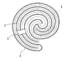
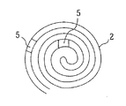
前記渦巻き型電極体1の構造を、図3を参照して詳細に説明すると、この渦巻き型電極体1の巻き初め端部では、負極板3が正極板2に包み込まれた状態とされ、巻き終り端部では、正極板2が負極板3に包み込まれた状態とされている。そのため、巻き初め端部及び巻き終り端部において支配極の正極に対向する面積が大きくなり、正極の利用効率がよい。
また、渦巻き型電極体1の最外周は負極板とされている。そのため、ニッケル・水素蓄電池のような電池缶の側面が導電性を有するタイプの電池の場合は、電池缶の側面から負極側の集電を行うことが可能なため、負極集電タブ6を省略してもよい。
【0026】
上記の正極集電タブ5は、1個設けられていたが、図6に示すように電極体1の周方向に複数個設けるようにしてもよく、また、図7に示すように電極体1の径方向に延びる架橋部5aにより、正極板の3以上の周回部分から集電するように構成してもよい。このようにすれば、さらに集電効果を高めることができる。但し、図6の構成では、集電タブを正・負極板の巻き取り前に固着させると巻き取りが困難となることから、この場合は巻き取り後に集電タブを固着させるようにするのが望ましい。尚、図6及び図7においては、理解の容易のため、負極板及びセパレータは省略されている。
【0027】
一方、負極集電タブ6の場合は、基本的には1個のみ設けられている。これは、負極集電タブを電池缶の底面にスポット溶接する際の作業の困難性によるものである。
【0028】
ここで、正極集電体2aとしては鉄、ステンレス鋼、ニッケル、アルミニウム等を用いることができ、負極集電体3aとしては鉄、ステンレス鋼、ニッケル、銅等を用いることができる。
また、正極活物質としては、アルカリ電池とした場合水酸化ニッケルを用い、リチウム電池とした場合はLiCoO2 、LiNiO2 、LiMn2 O4 等を用いることができ、また負極活物質としては、アルカリ電池とした場合水素吸蔵合金、水酸化カドミウムを、リチウム電池とした場合は天然黒鉛、その他の炭素材料を用いることができる。
また、正極集電タブ5としては鉄、ステンレス鋼、ニッケル、アルミニウム等を用いることができ、負極集電タブ6としては鉄、ステンレス鋼、ニッケル、銅等を用いることができる。
また、セパレータ4としては、多孔性のポリエチレン又はポリプロピレン等を用いることができる。
【0029】
次に上記構造の円筒型二次電池に製造方法について説明する。
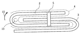
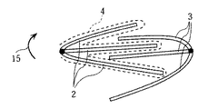
先ず、図8に示すように、一枚の正極板2と一枚の負極板3を、予めその長手方向に折り曲げておく。尚、正・負極板2,3が巻回された状態における曲率を考慮して、巻回状態において外側となる部分が長く、内側となる部分が短くなるように、正極板と負極板を折り曲げておく。次に、上記の折り曲げられた正極板2と折り曲げられた負極板3をセパレータ4を介して互いに噛み合い状態に組合わし、この組合わされた状態で、正極集電タブ5を正極板2の上端面に遊びをもたせてスポット溶接し、負極集電タブ6を負極板3の下端面に遊びをもたせてスポット溶接する。このように巻き取り前に集電タブ5,6を設けることにより、正・負極板がばらけることがなく、従って、巻きずれなく巻き取りを行うことができ、作業性が向上する。
【0030】
次に、巻芯13を正極板2の曲成部の内側近傍に挿入し、電極体1の最外周が負極板3となる巻回方向15に正極板及び負極板を巻回する。このように巻き初め端部を正極とすることにより、正極支配の電池にあっては、正極の利用効率を高めることができる。
こうして極板を巻き取り、渦巻き電極体1を製造した後、電池缶に渦巻き電極体1を収納し、負極集電タブ6を電池缶の底面11にスポット溶接し、正極集電タブ5を電池缶蓋10にスポット溶接して、円筒型二次電池が製造される。
【0031】
上述の前記渦巻き電極体は、一枚の正極板と一枚の負極板が、それぞれその長手方向に折り曲げられて巻回された構造であったけれども、複数枚の正・負極板がそれぞれその長手方向に折り曲げられて巻回された構造であってもよい。尚、この場合、巻き初め端部と巻き終り端部の少なくとも一方を予め固着しておいてもよく、このようにすれば更に円滑に巻き取りが可能となる。巻き初め端部と巻き終り端部のいずれか一方を固着する場合には、巻き初め端部を固着するのが望ましい。
【0032】
(第2実施形態)
本発明の円筒型二次電池の第2実施形態としては、図9に示すように、各複数枚の正極板2と負極板3を、セパレータ4を介して正極板2と負極板3が交互になるように重ね合わせて巻回して渦巻き電極体を製造するようにしてもよい。
【0033】
(第3実施形態)
本発明の円筒型二次電池の第3実施形態としては、図10に示すように、各複数枚の正極板2の一方の端部を予めスポット溶接して固着し、各複数枚の負極板3の一方の端部を予めスポット溶接して固着し、これら各複数枚の正極板2と負極板3をかみ合い状態に組み合わせ、この状態で巻回して渦巻き電極体1を製造するようにしてもよい。更に、各複数枚の正極板2の端部のみ固着し、各複数枚の負極板3の端部は固着しない状態で巻回して渦巻き電極体を製造するようにしてもよい。
【0034】
本発明における円筒型二次電池は、アルカリ電池、リチウムイオン電池、その他種々のタイプの電池にも適用することができる。る。
【0035】
【実施例】
〔実施例〕
実施例としては、上記第1実施形態に示した構造を有するニッケル・水素蓄電池を用いた。電池径、正極板、負極板、水素吸蔵合金電極、セパレータは、以下の寸法のものを用いた。
電池径: 34mm
正極板: 厚み0.60mm、縦長50mm、横長460mm
負極板: 厚み0.42mm、縦長50mm、横長600mm
セパレータ: 厚み0.15mm、縦長及び横長は正・負極板より若干大きい
尚、電池径26mm、30mm、43mmの各電池の正極板、負極板、セパレータの寸法は上記径が30mmの電池に準じた寸法のものを用いた。
このような構造の電池を、以下本発明電池Aと称する。
【0036】
〔比較例〕
比較例としては、電極体が特公昭和59−10536号公報に示すような、一枚の正極板と一枚の負極板をセパレータを介して重ね合わせて巻回した構造であることの他は実施例と同様の電池を用いた。このような構造の電池を、以下比較電池Xと称する。
【0037】
〔実験1〕
上記本発明電池Aと比較電池Xとにおける、電池径とエネルギー密度との関係を調べので、その結果を表1に示す。尚、本実験は、表2に示す電池条件の下、0.1Cの電流で16時間充電した後、電池電圧が1.0Vになるまで放電したときの放電容量で比較した。
【0038】
【表1】
【表2】
表1から明らかなように、径が30mm未満の電池では、本発明電池Aの方が比較電池Xより出力密度が小さくなっていることが認められる。これは、本発明電池Aでは、正・負極板を真円に近い状態で巻き取ることが困難なため、比較電池Xに比べてエネルギー密度が損なわれたもと考えられる。
一方、径が30mm以上の電池では、本発明電池Aの方が比較電池Xより出力密度が大きくなっていることが認められる。これは、本発明電池Aでは、巻き始めと巻き終り部分で極が包み込まれた状態となっているため、正極の対向面積が大きくなり、上記真円でないことに起因したエネルギー密度の損失よりも、正極の利用効率の効果の方が強く現れるためであると考えられる。
【0041】
尚、この実験結果によれば、本発明を径が30mm未満の電池に適用することは、適切でないとも考えられる。しかしながら、径が30mm未満の電池であっても、電池の種類、極板の厚み、極板の長さ等により、正極の利用効率の効果の方が強く現れるという効果が発揮される場合もあり、また、正・負極板を真円に近い状態で巻き取ることも可能である。従って、本発明は、電池の種類、極板の厚み、極板の長さ等を考慮すれば、小さい径の電池から大きい径の電池まで広範囲に適用することができる。
【0042】
【発明の効果】
以上で説明したように本発明によれば、正・負極板の巻回回数が減少するので、正・負極板の巻き取りが高速化され、その結果、生産性を向上できる。
【図面の簡単な説明】
【図1】本発明に係る円筒型二次電池の第1実施形態の主要部分の構造を示す分解斜視図である。
【図2】正極集電タブ付近の視図である。
【図3】渦巻き電極体を上方から見た図である。
【図4】渦巻き電極体の縦断面図である。
【図5】渦巻き電極体の一部拡大縦断面図である。
【図6】正極集電タブの他の実施形態を示す図である。
【図7】正極集電タブの他の実施形態を示す図である。
【図8】正・負極板の巻き取り前の状態を上方から見た図である。
【図9】本発明の第2実施形態の正・負極板の巻き取り前の状態を模式化した図である。
【図10】本発明の第3実施形態の正・負極板の巻き取り前の状態を模式化した図である。
【符号の説明】
1:渦巻き電極体
2:正極板
2a:正極集電体
2b:正極活物質層
3:負極板
3a:正極集電体
3b:正極活物質層
4:セパレータ
5:正極集電タブ
5a:架橋部
5b:連結部[0001]
BACKGROUND OF THE INVENTION
The present invention relates to a cylindrical secondary battery, and more particularly to an electrode structure of a cylindrical secondary battery.
[0002]
[Prior art]
In recent years, the size of batteries has been increasing in order to be used as a drive power source for electric vehicles that require high output and as a medium for storing power. Therefore, the electrode area increases, and in the case of a cylindrical secondary battery, the number of windings of the positive and negative plates increases in the manufacturing process of the spiral electrode body, and the winding time of the positive and negative plates increases. Increase is a problem.
[0003]
By the way, as shown in Japanese Patent Publication No. 59-10536, a typical spiral electrode body of this type of cylindrical secondary battery is formed by stacking one positive electrode plate and one negative electrode plate with a separator interposed therebetween. It is a structure wound together. When the battery having such a structure is applied to a large cylindrical rechargeable battery with high output , the number of windings of the positive and negative electrode plates is increased, and the winding speed cannot be increased.
[0004]
Therefore, in order to solve such a problem, a cylindrical secondary battery shown in Japanese Patent Publication No. 61-31594 has been proposed. In the cylindrical secondary battery shown in Japanese Patent Publication No. 61-31594, each positive / negative electrode plate is folded in a U shape in the width direction, and these positive / negative electrode plates are combined in a mutually engaged state. The spiral electrode body is manufactured by winding it in a spiral shape. Therefore, as shown in Japanese Patent Publication No. 59-10536, the number of windings is halved compared to the case where one positive electrode plate and one negative electrode plate are overlapped and wound. Can be taken up faster.
[0005]
[Problems to be solved by the invention]
However, the conventional cylindrical secondary battery has a structure in which the positive and negative plates folded in a U-shape are wound up. For example, when the battery diameter is 2 cm or more, the positive and negative electrodes are wound when the positive and negative plates are wound up. A tensile stress is generated on the plate, causing a winding deviation, and it is difficult to wind the plate with high accuracy. Moreover, if it takes up forcefully and winds up, partial distortion will arise in a positive / negative electrode board, and an active material will peel in the part.
[0006]
The present invention has been made in view of the above problems, and in a battery with a wide range of battery diameters from small to large battery diameters, the positive and negative electrode plates can be wound with high accuracy without winding deviation, In addition, it is an object of the present invention to provide a cylindrical secondary battery that can speed up winding of the positive and negative electrode plates by reducing the number of windings.
[0007]
[Means for Solving the Problems]
In order to achieve the above object, the cylindrical secondary battery of the present invention includes a positive electrode plate having a positive electrode active material layer formed on both surfaces of a strip-shaped positive electrode current collector, and a negative electrode active material on both surfaces of the strip-shaped negative electrode current collector. A cylindrical secondary battery having a spiral electrode body in which a negative electrode plate on which a material layer is formed is spirally wound via a strip-shaped separator, wherein the spiral electrode body includes a plurality of positive electrode plates and The negative electrode plate has a structure in which the positive electrode plate and the negative electrode plate are alternately overlapped and wound with a separator interposed therebetween.
[0008]
According to the above configuration, since the plurality of positive and negative electrode plates are overlapped and wound, the number of windings is reduced, and the positive and negative electrode plates can be wound at higher speed. As a result, productivity is improved. In particular, this effect is remarkable in a large battery having a large number of windings. In addition, even when the battery diameter is large, problems such as occurrence of winding deviation and separation of the active material as in a conventional cylindrical secondary battery (battery described in Japanese Patent Publication No. 61-31594) are eliminated. The positive and negative electrode plates can be wound with high accuracy without any winding deviation. Even if the present invention is applied to a battery having a small current collector thickness, such as a lithium ion battery, the number of windings can be reduced, and winding can be performed with high accuracy without any winding deviation. Of course.
[0009]
According to a second aspect of the present invention, in the above-described cylindrical secondary battery of the present invention , at least one of the positive electrode plate and the negative electrode plate constituting the spiral electrode body is fixed at the winding start end. It is characterized by being .
[0010]
Thus, if fixed at the winding start end, the positive and negative electrode plates can be wound more smoothly. In addition, since one pole is encased in the other pole at the winding start end, the counter electrode area increases in that portion, and the utilization efficiency of the electrode is improved.
[0011]
According to a third aspect of the present invention, there is provided a positive electrode plate in which a positive electrode active material layer is formed on both sides of a belt-like positive electrode current collector, and a negative electrode plate in which a negative electrode active material layer is formed on both surfaces of the belt-like negative electrode current collector. However, in the cylindrical secondary battery including a spiral electrode body wound spirally through a strip-shaped separator, the spiral electrode body includes a positive electrode plate and a negative electrode plate, each of which is bent in its longitudinal direction. It is characterized by being combined with each other via a joint and being wound in this combined state.
[0012]
According to the above configuration, in addition to the operational effect of the invention according to the second aspect, since one electrode plate is encased in the other electrode plate even at the winding end portion of the spiral electrode body, the counter electrode The area increases accordingly, and the utilization efficiency of the electrode can be increased.
[0013]
According to a fourth aspect of the present invention, in the cylindrical secondary battery according to any one of the first to third aspects , the positive electrode plate and the separator are disposed on the one end side in the height direction of the spiral electrode body. The negative electrode plate and the separator are formed to protrude from the positive electrode plate on the other end side in the height direction of the spiral electrode body, and further, a current collecting tab is provided on the one end side in the height direction. The current collecting tab includes a bridging portion that spans between the end portions of the inner circumferential portion and the outer circumferential portion of the positive electrode plate facing each other through the negative electrode plate, one end connected to the bridging portion, and the other end to the external terminal. And a connecting portion that is connected.
[0014]
According to the above configuration, it is possible to collect current from two locations of the positive electrode plate with one current collecting tab, and the current collecting effect is improved. Moreover, since the positive electrode plate and the separator protrude from the negative electrode plate on one end side in the height direction of the spiral electrode body, the current collecting tab and the negative electrode plate are prevented from being short-circuited.
[0015]
According to a fifth aspect of the present invention, in the cylindrical secondary battery according to the fourth aspect , the current collecting tab is provided before winding the positive and negative electrode plates.
[0016]
According to the above configuration, when winding the positive / negative electrode plate, there is no deviation between the polar plates, and the positive / negative electrode plate can be smoothly wound, thereby improving workability. Can do.
[0017]
According to a sixth aspect of the present invention, in the cylindrical secondary battery according to any one of the second to fifth aspects , the spiral electrode body is wound so that a winding start is a positive electrode and a winding end is a negative electrode. It is characterized by being.
[0018]
In addition to the configuration of the positive electrode at the start of winding and the negative electrode at the end of winding, in combination with the configuration according to the second or third aspect, use of the positive electrode at the winding start end and winding end in a positive electrode-dominated battery. Efficiency is improved.
[0019]
A seventh aspect of the present invention, in any one of the cylindrical secondary battery of the first to sixth aspects, the outermost periphery of the spiral electrode body, characterized in that it is a negative electrode.
[0020]
According to the said structure, since the outermost periphery of a spiral electrode body is a negative electrode, the current collection of the negative electrode side from the side surface of a battery can is attained.
[0021]
DETAILED DESCRIPTION OF THE INVENTION
(First embodiment)
1st Embodiment of this invention is described below based on FIGS. 2, 3, 4, and 8, the separator is indicated by a broken line for easy understanding.
FIG. 1 is an exploded perspective view showing the structure of the main part of a cylindrical secondary battery according to the present invention. In FIG. 1, the separator is omitted for easy understanding. The spiral electrode body 1 has a structure in which a
[0022]
A positive electrode
[0023]
Further, on the upper end side in the height direction of the spiral electrode body 1, as shown in FIG. 4, the upper end portions of the
[0024]
In addition, when the space | interval of the bridge | crosslinking
[0025]
The structure of the spiral electrode body 1 will be described in detail with reference to FIG. 3. At the initial winding end of the spiral electrode body 1, the
Further, the outermost periphery of the spiral electrode body 1 is a negative electrode plate. Therefore, in the case of a battery of a type in which the side surface of the battery can such as a nickel-hydrogen storage battery is conductive, it is possible to collect current on the negative electrode side from the side surface of the battery can, so the negative electrode
[0026]
Although one positive electrode
[0027]
On the other hand, in the case of the negative electrode
[0028]
Here, iron, stainless steel, nickel, aluminum or the like can be used as the positive electrode
Further, as the positive electrode active material, nickel hydroxide can be used for an alkaline battery, and LiCoO 2 , LiNiO 2 , LiMn 2 O 4, etc. can be used for a lithium battery. In the case of a battery, hydrogen storage alloy and cadmium hydroxide can be used, and in the case of a lithium battery, natural graphite and other carbon materials can be used.
Further, iron, stainless steel, nickel, aluminum or the like can be used for the positive electrode
As the
[0029]
Next, a manufacturing method for the cylindrical secondary battery having the above structure will be described.
First, as shown in FIG. 8, one
[0030]
Next, the winding
After winding the electrode plate in this way to manufacture the spiral electrode body 1, the spiral electrode body 1 is housed in a battery can, the negative electrode
[0031]
The above-described spiral electrode body has a structure in which one positive electrode plate and one negative electrode plate are each bent and wound in the longitudinal direction. It may be a structure that is bent in a direction and wound. In this case, at least one of the winding start end portion and the winding end end portion may be fixed in advance, so that the winding can be performed more smoothly. When either one of the winding start end and the winding end end is fixed, it is desirable to fix the winding start end.
[0032]
(Second Embodiment)
As a second embodiment of the cylindrical secondary battery of the present invention, as shown in FIG. 9, a plurality of
[0033]
(Third embodiment)
As a third embodiment of the cylindrical secondary battery of the present invention, as shown in FIG. 10, one end of each of the plurality of
[0034]
The cylindrical secondary battery in the present invention can also be applied to alkaline batteries, lithium ion batteries, and other various types of batteries. The
[0035]
【Example】
〔Example〕
As an example, a nickel-hydrogen storage battery having the structure shown in the first embodiment was used. The battery size, positive electrode plate, negative electrode plate, hydrogen storage alloy electrode, and separator used the following dimensions.
Battery diameter: 34mm
Positive electrode plate: thickness 0.60 mm, length 50 mm, width 460 mm
Negative electrode plate: thickness 0.42 mm, length 50 mm, width 600 mm
Separator: Thickness 0.15 mm, length and width are slightly larger than positive and negative plates. The positive electrode plate, negative electrode plate, and separator size of each battery with a battery diameter of 26 mm, 30 mm, and 43 mm are the same as the battery with the above diameter of 30 mm Dimensional ones were used.
The battery having such a structure is hereinafter referred to as the present invention battery A.
[0036]
[Comparative example]
As a comparative example, except that the electrode body has a structure in which one positive electrode plate and one negative electrode plate are overlapped and wound via a separator as shown in Japanese Patent Publication No. 59-10536. The same battery as in the example was used. The battery having such a structure is hereinafter referred to as a comparative battery X.
[0037]
[Experiment 1]
The relationship between the battery diameter and the energy density in the battery A of the present invention and the comparative battery X was examined, and the results are shown in Table 1. In this experiment, under the battery conditions shown in Table 2, the battery was charged with a current of 0.1 C for 16 hours, and then compared with the discharge capacity when discharged until the battery voltage reached 1.0 V.
[0038]
[Table 1]
[Table 2]
As is clear from Table 1, it is recognized that the battery A of the present invention has a lower output density than the comparative battery X in the battery having a diameter of less than 30 mm. This is probably because the energy density of the battery A of the present invention was impaired compared to the comparative battery X because it was difficult to wind the positive and negative electrode plates in a state close to a perfect circle.
On the other hand, in the battery having a diameter of 30 mm or more, it is recognized that the battery A of the present invention has a higher output density than the comparative battery X. This is because in the battery A of the present invention, the poles are encased at the beginning and end of winding, so the opposing area of the positive electrode is increased and the loss of energy density due to the fact that it is not a perfect circle. It is thought that this is because the effect of the utilization efficiency of the positive electrode appears more strongly.
[0041]
In addition, according to this experimental result, it is thought that it is not appropriate to apply this invention to the battery whose diameter is less than 30 mm. However, even in the case of a battery having a diameter of less than 30 mm, there may be an effect that the effect of using the positive electrode appears more strongly depending on the type of battery, the thickness of the electrode plate, the length of the electrode plate, and the like. It is also possible to wind the positive / negative electrode plate in a state close to a perfect circle. Therefore, the present invention can be applied in a wide range from a small diameter battery to a large diameter battery in consideration of the type of battery, the thickness of the electrode plate, the length of the electrode plate, and the like.
[0042]
【The invention's effect】
As described above, according to the present invention, the number of windings of the positive and negative electrode plates is reduced, so that the winding of the positive and negative electrode plates is speeded up. As a result, productivity can be improved.
[Brief description of the drawings]
FIG. 1 is an exploded perspective view showing a structure of a main part of a first embodiment of a cylindrical secondary battery according to the present invention.
FIG. 2 is a view in the vicinity of a positive electrode current collecting tab.
FIG. 3 is a view of a spiral electrode body as viewed from above.
FIG. 4 is a longitudinal sectional view of a spiral electrode body.
FIG. 5 is a partially enlarged longitudinal sectional view of a spiral electrode body.
FIG. 6 is a view showing another embodiment of the positive electrode current collecting tab.
FIG. 7 is a view showing another embodiment of the positive electrode current collecting tab.
FIG. 8 is a top view of the positive / negative electrode plate before winding.
FIG. 9 is a diagram schematically showing a state before winding up positive and negative electrode plates according to a second embodiment of the present invention.
FIG. 10 is a diagram schematically showing a state before winding of positive and negative electrode plates according to a third embodiment of the present invention.
[Explanation of symbols]
1: Spiral electrode body 2:
Claims (5)
前記渦巻き電極体は、正極板と負極板が、それぞれその長手方向に折り曲げられ、セパレータを介して互いに噛み合い状態に組合わされ、この組合わされた状態で巻回された構造とされていることを特徴とする円筒型二次電池。A positive electrode plate having a positive electrode active material layer formed on both sides of a strip-shaped positive electrode current collector and a negative electrode plate having a negative electrode active material layer formed on both surfaces of the strip-shaped negative electrode current collector are spirally wound via a strip-shaped separator. In a cylindrical secondary battery having a spiral electrode body wound in a shape,
The spiral electrode body has a structure in which a positive electrode plate and a negative electrode plate are each bent in the longitudinal direction, combined with each other via a separator, and wound in this combined state. A cylindrical secondary battery.
Priority Applications (1)
| Application Number | Priority Date | Filing Date | Title |
|---|---|---|---|
| JP26617397A JP3649876B2 (en) | 1997-09-30 | 1997-09-30 | Cylindrical secondary battery |
Applications Claiming Priority (1)
| Application Number | Priority Date | Filing Date | Title |
|---|---|---|---|
| JP26617397A JP3649876B2 (en) | 1997-09-30 | 1997-09-30 | Cylindrical secondary battery |
Publications (2)
| Publication Number | Publication Date |
|---|---|
| JPH11111325A JPH11111325A (en) | 1999-04-23 |
| JP3649876B2 true JP3649876B2 (en) | 2005-05-18 |
Family
ID=17427285
Family Applications (1)
| Application Number | Title | Priority Date | Filing Date |
|---|---|---|---|
| JP26617397A Expired - Fee Related JP3649876B2 (en) | 1997-09-30 | 1997-09-30 | Cylindrical secondary battery |
Country Status (1)
| Country | Link |
|---|---|
| JP (1) | JP3649876B2 (en) |
Families Citing this family (2)
| Publication number | Priority date | Publication date | Assignee | Title |
|---|---|---|---|---|
| CN103718340B (en) | 2011-08-02 | 2016-10-05 | 株式会社杰士汤浅国际 | Cylindrical battery and manufacturing method thereof |
| CN114883661B (en) * | 2021-02-05 | 2025-10-21 | 万魔声学股份有限公司 | Battery, method for preparing battery coil, and audio player |
-
1997
- 1997-09-30 JP JP26617397A patent/JP3649876B2/en not_active Expired - Fee Related
Also Published As
| Publication number | Publication date |
|---|---|
| JPH11111325A (en) | 1999-04-23 |
Similar Documents
| Publication | Publication Date | Title |
|---|---|---|
| JP3743781B2 (en) | Nonaqueous electrolyte secondary battery | |
| US20060147793A1 (en) | Jelly-roll type battery unit and winding method thereof and lithium secondary battery comprising the same | |
| JPH0917441A (en) | Rectangular battery with a built-in bent electrode plate | |
| JP3702308B2 (en) | Nonaqueous electrolyte secondary battery | |
| CN212517286U (en) | Roll core, battery and electronic product | |
| JP2005166664A (en) | Secondary battery | |
| JP2006156365A (en) | Lithium secondary battery | |
| KR100515832B1 (en) | Electrode assembly of secondary battery | |
| JPH11329398A (en) | Wound electrode battery | |
| JP2000106167A (en) | Battery | |
| US6258487B1 (en) | Lithium secondary battery including a divided electrode base layer | |
| JP3221324B2 (en) | Thin battery and manufacturing method thereof | |
| JP3588264B2 (en) | Rechargeable battery | |
| JPH1173995A (en) | Cylindrical non-aqueous electrolyte secondary battery and method of manufacturing the same | |
| JPH11265732A (en) | Non-aqueous electrolyte battery | |
| JPH10125348A (en) | Battery | |
| JP3119259B2 (en) | Non-aqueous electrolyte secondary battery | |
| JPH09161837A (en) | Cylindrical battery | |
| KR20230073955A (en) | Electrode assembly and secondary battery comprising the same | |
| JP3649876B2 (en) | Cylindrical secondary battery | |
| CN115911774B (en) | Battery cells and electrical equipment | |
| CN221447208U (en) | Electrode pieces, electrode assemblies, battery cells, batteries and electrical devices | |
| JPH1064588A (en) | Cylindrical lithium secondary battery | |
| JP2000090977A (en) | Non-aqueous electrolyte secondary battery | |
| JP2000353539A (en) | Electrode-wound secondary battery |
Legal Events
| Date | Code | Title | Description |
|---|---|---|---|
| A977 | Report on retrieval |
Free format text: JAPANESE INTERMEDIATE CODE: A971007 Effective date: 20040519 |
|
| A131 | Notification of reasons for refusal |
Free format text: JAPANESE INTERMEDIATE CODE: A131 Effective date: 20041116 |
|
| A521 | Written amendment |
Free format text: JAPANESE INTERMEDIATE CODE: A523 Effective date: 20050114 |
|
| TRDD | Decision of grant or rejection written | ||
| A01 | Written decision to grant a patent or to grant a registration (utility model) |
Free format text: JAPANESE INTERMEDIATE CODE: A01 Effective date: 20050208 |
|
| A61 | First payment of annual fees (during grant procedure) |
Free format text: JAPANESE INTERMEDIATE CODE: A61 Effective date: 20050216 |
|
| FPAY | Renewal fee payment (event date is renewal date of database) |
Free format text: PAYMENT UNTIL: 20090225 Year of fee payment: 4 |
|
| LAPS | Cancellation because of no payment of annual fees |