JP3649871B2 - Roll forming method and roll forming stand - Google Patents
Roll forming method and roll forming stand Download PDFInfo
- Publication number
- JP3649871B2 JP3649871B2 JP24451497A JP24451497A JP3649871B2 JP 3649871 B2 JP3649871 B2 JP 3649871B2 JP 24451497 A JP24451497 A JP 24451497A JP 24451497 A JP24451497 A JP 24451497A JP 3649871 B2 JP3649871 B2 JP 3649871B2
- Authority
- JP
- Japan
- Prior art keywords
- roll
- forming
- skelp
- load cell
- roll forming
- Prior art date
- Legal status (The legal status is an assumption and is not a legal conclusion. Google has not performed a legal analysis and makes no representation as to the accuracy of the status listed.)
- Expired - Fee Related
Links
Images
Landscapes
- Bending Of Plates, Rods, And Pipes (AREA)
Description
【0001】
【発明の属する技術分野】
本発明は、ロール成形方法およびロール成形スタンドに関し、詳しくは、温間温度域に加熱されたスケルプ(管素材としての帯鋼類)を連続して管状にロール成形するのに好適なロール成形方法およびロール成形スタンドに関する。
【0002】
【従来の技術】
溶接鋼管は、従来、鍛接管、電縫管に大別される。
鍛接管は、スケルプを連続的に加熱炉で1350〜1400℃に加熱し、成形ロールでV形のオープン部を有する管状に成形し、オープン部の両端をなすエッジ部を酸素ブローによる酸化熱で更に昇温させた後、V先端のところを鍛接ロールで加圧・接合する工程で造管される。成形ロールとしては、一般に2本1組の孔型ロールが用いられ、熱損傷を防ぐため作業中のロールには常時外部から冷却水がかけられる。なお、鍛接管は1350℃以上に赤熱されているので、成形ロールの冷却水がかかったくらいでは、鍛接できなくなるほど冷えてしまうことはない。
【0003】
一方、電縫管は、常温のスケルプを連続的に成形装置でV形のオープン部を有する管状に成形し、オープン部の両端をなすエッジ部を高周波により融点以上の温度域に誘導加熱または通電加熱した後、V先端のところをスクイズロールで加圧・接合する工程で造管される。成形装置は、普通十数段の成形用ロール(初期成形用のブレイクダウンロール、中期成形用のサイドロールおよび/またはケージロール、終期成形用のフィンパスロールなど)からなり、スケルプ幅を徐々に湾曲させて最終的に円筒状のオープン管に成形する。
【0004】
【発明が解決しようとする課題】
鍛接管は、造管速度が300 m/min 以上と速く生産性は高いが、1350℃以上の高温に加熱されるから、スケルプエッジにスケールが残りやすいためシーム部の強度が母材部に比べてかなり劣ると共に管表面にスケールが生成して表面肌が悪いことから、JISのSTK等の強度信頼性や表面品質を要求される高級鋼管には適用できない。
【0005】
電縫管は、常温で造管されるからシーム品質・表面肌は良好で、高級鋼管に適用されているが、スケルプエッジが溶融・加圧されてできたシーム部の大きな溶接ビードをオンラインで切削する必要があって、造管速度を高々100 m/min 程度までしか上げられず、生産能率が悪い。
これらの問題点は、本発明者らの創案になる、スケルプをスケール生成量の少ない温間温度域(例えば600 ℃前後)に加熱した後、電縫管同様に成形し、エッジ部を大きな溶接ビードの生じない融点未満の温度域に高周波加熱して加圧・接合するという新造管法(電縫型固相圧接造管法と仮称)によれば一挙に解決できる。
【0006】
しかし、この新造管法では、温間温度域にあるスケルプを成形装置で成形するため、成形用ロールの温度が上昇するためロールが熱膨張して上下のロールギャップが時間とともに狭まり、スケルプの連続成形が困難となる問題がある。これを防止するためにロールの水冷が必要となるが、外部水冷を行うと、鍛接管の場合とは異なり、スケルプにかかる冷却水がスケルプ温度を下げてしまい、エッジ部を高周波加熱によって融点直下の固相圧接可能温度域に保つことが難しくなる。
【0007】
そこで、本発明は、温間スケルプをロール成形する際に成形ロールが熱膨張しても当該スケルプの連続成形を可能ならしめるロール成形方法およびロール成形スタンドを提供することを目的とする。
【0008】
【課題を解決するための手段】
本発明は、成形用のロールを水平かつ上下平行に配置してなるロール成形スタンドを用いて温間スケルプを管状に連続成形するロール成形方法において、上ロールの支持部にロードセルを設けて成形力を連続的に実測し、この実測値が鋼種、スケルプ厚、成形厚に応じて選定した所定の上限値を超えないように上ロールの高さ位置を随時調節しながら連続成形することを特徴とするロール成形方法である。
【0009】
また、本発明は、成形用のロールが水平かつ上下平行に配置されてなり温間スケルプを管状に連続成形するロール成形スタンドにおいて、上ロールを昇降させるACサーボモータと、上ロールの支持部に配設され成形力を連続的に出力するロードセルと、該ロードセル出力を鋼種、スケルプ厚、成形厚に応じて選定した所定の上限値と比較しロードセル出力が前記上限値を超えないように前記ACサーボモータを駆動して上ロールの高さ位置を調節するロールギャップ制御装置とを備えたことを特徴とするロール成形スタンドである。
【0010】
【発明の実施の形態】
高温のスケルプを連続成形すると、ロール温度が上昇し、ロールが熱膨張することにより上下のロールギャップが狭まり、スケルプに作用する上下ロールの挟圧力が増大して遂にはスケルプが通らなくなる。
これに対し、本発明では、上ロールの支持部にロードセルを設けて成形力(=スケルプの挟圧反力)を連続的に実測し、この実測値が所定値を超えないように上ロールの高さを随時調節しながら成形するようにしたから、この所定値をスケルプ成形可能範囲内の適当な値(例えば上限近くの値)に設定し、例えば成形力の実測値が所定値を超えそうになった時に、上ロールを上昇させてこの実測値を初期プリセット値に戻す等の動的な上ロール位置制御を行うことにより、ロール水冷を行わなくても、スケルプ不通による成形中断トラブルなく、連続成形を行うことができる。
【0011】
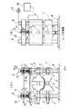
図1は、本発明のロール成形スタンドの一例を示す(a)は模式的正面図、(b)は(a)のAA矢視図である。特に限定されないが、この例では、スケルプsを成形する水平配置の上ロール1、下ロール2は左右分割型であり、上ロール1は左右独立に軸受箱3と軸方向連動可能とされ、左右の軸受箱3、3を左右の上支持枠4、4にそれぞれ互いに逆螺合させ幅変更ギヤロッド5で同期回転させることで、左右のロール間隔を変更できるように構成されている。下ロール2の左右の軸受箱3、3は下支持枠7、7に軸方向移動可能に支持されている。
【0012】
上支持枠4、下支持枠7は基台8に立てた支柱6で上下摺動可能に支持されている。ウォームギヤ11を備えた梁枠10が上支持枠4の上方で支柱6に固定され、上支持枠4は、ウォームギヤ11に噛合する昇降ギヤロッド12を有し、この噛合によって高さ位置調節可能に支持されている。ウォームギヤ11の回転はACサーボモータ13により駆動される。なお、下支持枠7は基台8に固定したジャッキ9によって高さ位置調節可能に支持されている。
【0013】
本実施形態では、上ロール1の支持部としての上支持枠4に成形力検出用のロードセル14を配置し、ロードセル14の出力を連続的にロールギャップ制御装置15に取り込む。ロールギャップ制御装置15は、取り込まれたロードセル出力を所定の上限値と比較し、このロードセル出力が上限値を超ないように随時ACサーボモータ13を回転させて上ロール1の高さ位置を調節する。
【0014】
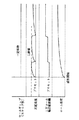
図2は、本発明の実施形態の一例を示すタイミングチャートである。スケルプが成形前に600 ℃前後に加熱されているので、ロール温度の経時上昇に伴い上下ロールが熱膨張し、スケルプからの反力が漸増することにより、ロードセル出力は、プリセット値から徐々に上昇するがプリセット値を超える寸前でACサーボモータ13を所定量だけ回転して上ロール1の高さ位置を高く(上下ロール軸間距離を拡大)することで、プリセット値に復帰するよう調節される。これにより、ロールギャップをスケルプ厚に応じた一定値に制御することができ、スケルプ不通による成形中断トラブルは発生しなくなる。
【0015】
なお、成形力の上限値は、鋼種、スケルプ厚、成形量(管外径)等の要因により変わるので、これら要因との関係を予備実験や操業実績解析等により把握しておき、その関係に従って適正な値を選定する。
【0016】
【発明の効果】
かくして、本発明によれば、電縫型固相圧接造管法による温間スケルプのロール成形段階で、成形ロールが熱膨張しても当該スケルプの連続成形が可能となり、シーム品質および表面肌に優れる鋼管を高能率で生産できるようになるという優れた効果を奏する。
【図面の簡単な説明】
【図1】本発明のロール成形スタンドの一例を示す(a)は模式的正面図、(b)は(a)のAA矢視図である。
【図2】本発明の実施形態の一例を示すタイミングチャートである。
【符号の説明】
1 上ロール
2 下ロール
3 軸受箱
4 上支持枠
5 幅変更ギヤロッド
6 支柱
7 下支持枠
8 基台
9 ジャッキ
10 梁枠
11 ウォームギヤ
12 昇降ギヤロッド
13 ACサーボモータ
14 ロードセル
15 ロールギャップ制御装置
s スケルプ[0001]
BACKGROUND OF THE INVENTION
The present invention relates to a roll forming method and a roll forming stand, and more specifically, a roll forming method suitable for continuously forming a skelp (a steel strip as a tube material) heated in a warm temperature range into a tubular shape. And a roll forming stand.
[0002]
[Prior art]
Conventionally, welded steel pipes are roughly classified into forged welded pipes and ERW pipes.
Forged welded tube, skelp is continuously heated to 1350-1400 ° C in a heating furnace, formed into a tube with a V-shaped open part with a forming roll, and the edges forming both ends of the open part are oxidized by heat generated by oxygen blow. After the temperature is further raised, the tube is formed in a process in which the tip of the V is pressed and joined with a forging roll. As a forming roll, a set of two perforated rolls is generally used, and cooling water is constantly applied from the outside to the working roll in order to prevent thermal damage. In addition, the forged pipe is heated to 1350 ° C or higher, so it will not be cooled so much that it cannot be forged as long as the cooling water of the forming roll is applied.
[0003]
On the other hand, the ERW tube is formed by continuously forming a normal temperature skelp into a tubular shape having V-shaped open portions with a forming device, and induction heating or energization of the edge portions forming both ends of the open portion to a temperature range above the melting point by high frequency. After heating, the tube is formed in a process of pressing and joining the tip of the V with a squeeze roll. The molding equipment usually consists of a dozen rolls (breakdown rolls for initial molding, side rolls and / or cage rolls for medium-term molding, fin pass rolls for final molding, etc.), and the skelp width is gradually increased. It is bent and finally formed into a cylindrical open tube.
[0004]
[Problems to be solved by the invention]
Forged pipes have a high pipe-making speed of 300 m / min or higher and high productivity, but because they are heated to a high temperature of 1350 ° C or higher, the scale is likely to remain on the skelp edge, so the strength of the seam is higher than that of the base metal Since it is considerably inferior and scale is generated on the pipe surface and the surface is poor, it cannot be applied to high-grade steel pipes that require strength reliability and surface quality such as JIS STK.
[0005]
ERW pipes are manufactured at room temperature, so seam quality and surface texture are good, and they are applied to high-grade steel pipes. On the other hand, a large weld bead with a seam formed by melting and pressing the skelp edge is cut online. Therefore, the pipe making speed can only be increased up to about 100 m / min, and the production efficiency is poor.
These problems are the original idea of the present inventors. After heating the skelp to a warm temperature range (eg, around 600 ° C) with a small amount of scale, it is molded in the same way as an ERW pipe, and the edge part is welded greatly. This can be solved all at once by a new pipe forming method (tentative name: electro-sealing type solid-state pressure welding pipe method) in which high-frequency heating is applied to a temperature range below the melting point at which no bead occurs and pressure is applied and bonded.
[0006]
However, in this new pipe forming method, a skelp in the warm temperature range is formed with a molding device, so the temperature of the forming roll rises, the roll expands thermally, and the upper and lower roll gaps narrow with time, and the skelp continues. There is a problem that molding becomes difficult. In order to prevent this, water cooling of the roll is necessary, but when external water cooling is performed, the cooling water applied to the skelp lowers the skelp temperature unlike the case of the forged welded tube, and the edge part is directly below the melting point by high frequency heating. It is difficult to keep the temperature within the solid pressure welding range.
[0007]
Therefore, an object of the present invention is to provide a roll forming method and a roll forming stand that enable continuous forming of the skelp even when the forming roll is thermally expanded when roll forming the warm skelp.
[0008]
[Means for Solving the Problems]
The present invention relates to a roll forming method in which a warm skelp is continuously formed into a tubular shape using a roll forming stand in which forming rolls are arranged horizontally and vertically in parallel. It is characterized by continuously forming while adjusting the height position of the upper roll as needed so that this measured value does not exceed the predetermined upper limit value selected according to the steel type, skelp thickness and forming thickness. This is a roll forming method.
[0009]
Further, the present invention provides a roll forming stand in which forming rolls are arranged horizontally and vertically in parallel and continuously form a warm skelp into a tubular shape. A load cell that continuously outputs the forming force, and compares the load cell output with a predetermined upper limit value selected according to the steel type, skelp thickness, and molding thickness so that the load cell output does not exceed the upper limit value. A roll forming stand comprising: a roll gap control device that drives a servo motor to adjust the height position of the upper roll.
[0010]
DETAILED DESCRIPTION OF THE INVENTION
When a hot skelp is continuously formed, the roll temperature rises and the roll expands thermally, so that the upper and lower roll gaps are narrowed, and the sandwiching pressure between the upper and lower rolls acting on the skelp is increased, so that the skelp cannot pass.
On the other hand, in the present invention, a load cell is provided at the support portion of the upper roll, and the forming force (= the pressing reaction force of the skelp) is continuously measured, so that the measured value does not exceed a predetermined value. Since the molding is performed while adjusting the height as needed, this predetermined value is set to an appropriate value within the skelp molding possible range (for example, a value near the upper limit), for example, the measured value of the molding force is likely to exceed the predetermined value. By performing dynamic upper roll position control such as raising the upper roll and returning this measured value to the initial preset value, there is no trouble in interrupting the molding due to the lack of skelp, without performing roll water cooling. Continuous molding can be performed.
[0011]
FIG. 1A is a schematic front view showing an example of a roll forming stand of the present invention, and FIG. 1B is a view taken along arrow AA in FIG. In this example, the horizontal roll upper roll 1 and the
[0012]
The upper support frame 4 and the
[0013]
In the present embodiment, the
[0014]
FIG. 2 is a timing chart showing an example of the embodiment of the present invention. Since the skelp is heated to around 600 ° C before molding, the upper and lower rolls thermally expand as the roll temperature rises, and the reaction force from the skelp gradually increases, so the load cell output gradually increases from the preset value. However, it is adjusted to return to the preset value by rotating the
[0015]
Note that the upper limit of the forming force varies depending on factors such as steel type, skelp thickness, forming amount (tube outer diameter), etc., so grasp the relationship with these factors through preliminary experiments and operational performance analysis, etc. you select the appropriate value.
[0016]
【The invention's effect】
Thus, according to the present invention, in the roll forming stage of the warm skelp by the ERW type solid phase pressure welding tube method, the skelp can be continuously formed even if the forming roll is thermally expanded, and the seam quality and the surface skin are improved. It has an excellent effect that an excellent steel pipe can be produced with high efficiency.
[Brief description of the drawings]
FIG. 1A is a schematic front view showing an example of a roll forming stand of the present invention, and FIG. 1B is a view taken along the line AA in FIG.
FIG. 2 is a timing chart showing an example of an embodiment of the present invention.
[Explanation of symbols]
DESCRIPTION OF SYMBOLS 1
10 Beam frame
11 Worm gear
12 Lifting gear rod
13 AC servo motor
14 Load cell
15 Roll gap controller s Skelp
Claims (2)
Priority Applications (9)
| Application Number | Priority Date | Filing Date | Title |
|---|---|---|---|
| JP24451497A JP3649871B2 (en) | 1997-09-10 | 1997-09-10 | Roll forming method and roll forming stand |
| US09/149,576 US6041632A (en) | 1997-09-10 | 1998-09-08 | Pipe forming roll apparatus and method |
| IDP981210A ID21005A (en) | 1997-09-10 | 1998-09-09 | PIPING SHAPER EQUIPMENT AND METHODS |
| BR9803403-0A BR9803403A (en) | 1997-09-10 | 1998-09-09 | Apparatus and method of a tube forming cylinder. |
| KR1019980037132A KR100361052B1 (en) | 1997-09-10 | 1998-09-09 | Pipe forming roll apparatus and method |
| EP98307276A EP0901846A3 (en) | 1997-09-10 | 1998-09-09 | Pipe forming roll apparatus and method |
| CN98119242A CN1090065C (en) | 1997-09-10 | 1998-09-09 | Machine frame for roller forming and forming method |
| CA002281295A CA2281295A1 (en) | 1997-09-10 | 1999-09-02 | Pipe forming roll apparatus and method |
| US09/506,025 US6216940B1 (en) | 1997-09-10 | 2000-02-17 | Pipe forming roll apparatus and method |
Applications Claiming Priority (2)
| Application Number | Priority Date | Filing Date | Title |
|---|---|---|---|
| JP24451497A JP3649871B2 (en) | 1997-09-10 | 1997-09-10 | Roll forming method and roll forming stand |
| CA002281295A CA2281295A1 (en) | 1997-09-10 | 1999-09-02 | Pipe forming roll apparatus and method |
Publications (2)
| Publication Number | Publication Date |
|---|---|
| JPH1177169A JPH1177169A (en) | 1999-03-23 |
| JP3649871B2 true JP3649871B2 (en) | 2005-05-18 |
Family
ID=25681165
Family Applications (1)
| Application Number | Title | Priority Date | Filing Date |
|---|---|---|---|
| JP24451497A Expired - Fee Related JP3649871B2 (en) | 1997-09-10 | 1997-09-10 | Roll forming method and roll forming stand |
Country Status (1)
| Country | Link |
|---|---|
| JP (1) | JP3649871B2 (en) |
Cited By (1)
| Publication number | Priority date | Publication date | Assignee | Title |
|---|---|---|---|---|
| KR20210032234A (en) * | 2019-09-16 | 2021-03-24 | 주식회사 대천 | Tube mill with tube twist protection |
Families Citing this family (1)
| Publication number | Priority date | Publication date | Assignee | Title |
|---|---|---|---|---|
| KR101779334B1 (en) | 2015-12-29 | 2017-09-19 | 주식회사 성우하이텍 | Roll forming device for forming variable thickness plate |
-
1997
- 1997-09-10 JP JP24451497A patent/JP3649871B2/en not_active Expired - Fee Related
Cited By (2)
| Publication number | Priority date | Publication date | Assignee | Title |
|---|---|---|---|---|
| KR20210032234A (en) * | 2019-09-16 | 2021-03-24 | 주식회사 대천 | Tube mill with tube twist protection |
| KR102242956B1 (en) | 2019-09-16 | 2021-04-21 | 주식회사 대천 | Tube mill with tube twist protection |
Also Published As
| Publication number | Publication date |
|---|---|
| JPH1177169A (en) | 1999-03-23 |
Similar Documents
| Publication | Publication Date | Title |
|---|---|---|
| US6216940B1 (en) | Pipe forming roll apparatus and method | |
| US4150279A (en) | Ring rolling methods and apparatus | |
| RU1806030C (en) | Method of making rectangular hollow steel shapes | |
| US2959849A (en) | Method and apparatus for making pipe | |
| JP3649871B2 (en) | Roll forming method and roll forming stand | |
| KR100340816B1 (en) | How to increase yield strength of cold rolled steel | |
| CN106270218B (en) | A kind of online controllable continuous based on Multi-sensor Fusion hinders method for heating and controlling certainly | |
| CN102152070A (en) | Method for manufacturing ring-shaped piece | |
| US3263053A (en) | Tube forming apparatus | |
| JP3052555B2 (en) | Manufacturing method of small-diameter ERW pipe | |
| JP3812998B2 (en) | Stand for roll forming | |
| JP2000210714A (en) | Equipment line for steel pipe production | |
| CN114522981A (en) | Heating device for round tube square tube and processing system with same | |
| JP2849595B2 (en) | Forming method and equipment for large diameter square steel pipe | |
| KR20070030229A (en) | Improved welding of hollow flanged members | |
| JP3348822B2 (en) | Manufacturing method of bonded steel pipe | |
| JP3651279B2 (en) | Seam processing temperature control equipment line | |
| JPH0592214A (en) | Method and device for forming large diameter square steel tube | |
| RU2173598C2 (en) | Method for making expanded annular blanks of high alloys | |
| JPH06330177A (en) | Heat treatment apparatus for round corner part of large diameter square steel tube | |
| SU1692790A1 (en) | Method for making bimetallic hollow articles by diffusion welding | |
| JPH08243646A (en) | Method of manufacturing square steel pipe | |
| JPS63224883A (en) | Warm resistance welding method | |
| JP3270719B2 (en) | Cooling method of pressure welded steel pipe | |
| JP2888786B2 (en) | Method for producing welded H-section steel |
Legal Events
| Date | Code | Title | Description |
|---|---|---|---|
| A977 | Report on retrieval |
Free format text: JAPANESE INTERMEDIATE CODE: A971007 Effective date: 20041116 |
|
| A131 | Notification of reasons for refusal |
Free format text: JAPANESE INTERMEDIATE CODE: A131 Effective date: 20041124 |
|
| A521 | Written amendment |
Free format text: JAPANESE INTERMEDIATE CODE: A523 Effective date: 20050118 |
|
| TRDD | Decision of grant or rejection written | ||
| A01 | Written decision to grant a patent or to grant a registration (utility model) |
Free format text: JAPANESE INTERMEDIATE CODE: A01 Effective date: 20050215 |
|
| A61 | First payment of annual fees (during grant procedure) |
Free format text: JAPANESE INTERMEDIATE CODE: A61 Effective date: 20050216 |
|
| R150 | Certificate of patent or registration of utility model |
Free format text: JAPANESE INTERMEDIATE CODE: R150 |
|
| LAPS | Cancellation because of no payment of annual fees |