JP3649838B2 - Drain water evaporator for refrigerator - Google Patents
Drain water evaporator for refrigerator Download PDFInfo
- Publication number
- JP3649838B2 JP3649838B2 JP02610897A JP2610897A JP3649838B2 JP 3649838 B2 JP3649838 B2 JP 3649838B2 JP 02610897 A JP02610897 A JP 02610897A JP 2610897 A JP2610897 A JP 2610897A JP 3649838 B2 JP3649838 B2 JP 3649838B2
- Authority
- JP
- Japan
- Prior art keywords
- evaporation
- refrigerator
- drain water
- plate
- receiving member
- Prior art date
- Legal status (The legal status is an assumption and is not a legal conclusion. Google has not performed a legal analysis and makes no representation as to the accuracy of the status listed.)
- Expired - Fee Related
Links
- XLYOFNOQVPJJNP-UHFFFAOYSA-N water Substances O XLYOFNOQVPJJNP-UHFFFAOYSA-N 0.000 title claims description 76
- 238000001704 evaporation Methods 0.000 claims description 179
- 230000008020 evaporation Effects 0.000 claims description 135
- 239000000463 material Substances 0.000 claims description 16
- 238000007664 blowing Methods 0.000 claims description 5
- 238000012423 maintenance Methods 0.000 description 8
- 238000004140 cleaning Methods 0.000 description 7
- 230000005484 gravity Effects 0.000 description 3
- 238000004519 manufacturing process Methods 0.000 description 3
- 238000009423 ventilation Methods 0.000 description 3
- 229910000831 Steel Inorganic materials 0.000 description 2
- 238000001816 cooling Methods 0.000 description 2
- 239000002537 cosmetic Substances 0.000 description 2
- 238000010586 diagram Methods 0.000 description 2
- 239000000835 fiber Substances 0.000 description 2
- 230000012447 hatching Effects 0.000 description 2
- 238000005192 partition Methods 0.000 description 2
- 239000010959 steel Substances 0.000 description 2
- 238000010521 absorption reaction Methods 0.000 description 1
- 238000005452 bending Methods 0.000 description 1
- 238000007599 discharging Methods 0.000 description 1
- 239000000428 dust Substances 0.000 description 1
- 230000000694 effects Effects 0.000 description 1
- 239000004744 fabric Substances 0.000 description 1
- 235000013410 fast food Nutrition 0.000 description 1
- 238000007710 freezing Methods 0.000 description 1
- 230000008014 freezing Effects 0.000 description 1
- 238000000465 moulding Methods 0.000 description 1
- 238000005057 refrigeration Methods 0.000 description 1
- 239000011347 resin Substances 0.000 description 1
- 229920005989 resin Polymers 0.000 description 1
- 229910001220 stainless steel Inorganic materials 0.000 description 1
- 239000010935 stainless steel Substances 0.000 description 1
- 239000002759 woven fabric Substances 0.000 description 1
Images

Classifications
-
- F—MECHANICAL ENGINEERING; LIGHTING; HEATING; WEAPONS; BLASTING
- F25—REFRIGERATION OR COOLING; COMBINED HEATING AND REFRIGERATION SYSTEMS; HEAT PUMP SYSTEMS; MANUFACTURE OR STORAGE OF ICE; LIQUEFACTION SOLIDIFICATION OF GASES
- F25D—REFRIGERATORS; COLD ROOMS; ICE-BOXES; COOLING OR FREEZING APPARATUS NOT OTHERWISE PROVIDED FOR
- F25D2321/00—Details or arrangements for defrosting; Preventing frosting; Removing condensed or defrost water, not provided for in other groups of this subclass
- F25D2321/14—Collecting condense or defrost water; Removing condense or defrost water
- F25D2321/144—Collecting condense or defrost water; Removing condense or defrost water characterised by the construction of drip water collection pans
- F25D2321/1442—Collecting condense or defrost water; Removing condense or defrost water characterised by the construction of drip water collection pans outside a refrigerator
-
- F—MECHANICAL ENGINEERING; LIGHTING; HEATING; WEAPONS; BLASTING
- F25—REFRIGERATION OR COOLING; COMBINED HEATING AND REFRIGERATION SYSTEMS; HEAT PUMP SYSTEMS; MANUFACTURE OR STORAGE OF ICE; LIQUEFACTION SOLIDIFICATION OF GASES
- F25D—REFRIGERATORS; COLD ROOMS; ICE-BOXES; COOLING OR FREEZING APPARATUS NOT OTHERWISE PROVIDED FOR
- F25D2321/00—Details or arrangements for defrosting; Preventing frosting; Removing condensed or defrost water, not provided for in other groups of this subclass
- F25D2321/14—Collecting condense or defrost water; Removing condense or defrost water
- F25D2321/147—Collecting condense or defrost water; Removing condense or defrost water characterised by capillary, wick, adsorbent, or evaporation elements
Landscapes
- Removal Of Water From Condensation And Defrosting (AREA)
Description
【0001】
【発明の属する技術分野】
本発明は、冷蔵庫の冷却器或いは貯蔵室などからのドレン水を蒸発処理するためのドレン水蒸発装置に関するものである。
【0002】
【従来の技術】
従来よりこの種業務用・家庭用の冷蔵庫は、例えば特開平6−159907号公報(F25D21/14)に示される如く、本体側に形成された支持部材に蒸発皿を挿脱自在に支持させ、この蒸発皿上にはドレンホースを引き込んで冷却器や貯蔵室からのドレン水を排出すると共に、蒸発皿には機械室内に設けられた送風ファンにより送風して、このドレン水を蒸発処理する構成とされている。
【0003】
また、前記公報では蒸発皿内に繊維織布や多孔質プラスチック材などの給水性の良い材料を板状に成形した蒸発板を複数枚設けて蒸発表面積を拡大し、ドレン水をこの蒸発板に吸収させ、送風中に発散させることによって蒸発処理能力を向上させている。更に、近年では係る送風ファンと蒸発皿を受ける受け部材とを一体にユニット化し、このユニットを冷蔵庫本体に取り付ける蒸発装置も開発されている。
【0004】
【発明が解決しようとする課題】
しかしながら、係る従来の蒸発装置は冷蔵庫本体に容易に取り付け、或いは、冷蔵庫本体から容易に取り外すことが出来なかったため、組立時、或いは、送風ファンが故障した際のメンテナンス作業が極めて面倒なものとなっていた。
【0005】
また、蒸発板は通常複数枚並設され、それらを接続部材を介して連結すると共に、最終的にステープラーにて止める構造であったため、ドレン水に含まれる塵埃により汚れた場合、清掃することが極めて困難であった。更に、従来では単に蒸発板を並設するのみの構造であったため、蒸発能力の向上にも限界があった。
【0006】
本発明は、係る従来の技術的課題を解決するために成されたものであり、組立及びメンテナンス作業性を向上させ、更には蒸発能力の向上を図った冷蔵庫のドレン水蒸発装置を提供するものである。
【0007】
【課題を解決するための手段】
本発明のドレン水蒸発装置は、冷蔵庫本体に取り付けられる受け部材と、この受け部材奥部に設けられたファンケース内に配設された送風ファンと、受け部材に保持され、前方より挿脱自在とされた蒸発皿と、この蒸発皿内に配置された給水性の良い蒸発板とを備え、蒸発皿上に臨んで冷蔵庫本体からのドレンホースが引き込まれるものであって、受け部材を冷蔵庫本体に前方より着脱自在に取り付けると共に、ドレンホースの引き込み位置及び送風ファンへの給電線の接続位置を受け部材の前部に配置したものである。
【0008】
本発明によれば、冷蔵庫本体に取り付けられる受け部材と、この受け部材奥部に設けられたファンケース内に配設された送風ファンと、受け部材に保持され、前方より挿脱自在とされた蒸発皿と、この蒸発皿内に配置された給水性の良い蒸発板とを備え、蒸発皿上に臨んで冷蔵庫本体からのドレンホースが引き込まれるドレン水蒸発装置において、受け部材を冷蔵庫本体に前方より着脱自在に取り付けると共に、ドレンホースの引き込み位置及び送風ファンへの給電線の接続位置を受け部材の前部に配置した構造としたので、冷蔵庫を組み立てる際の冷蔵庫本体への組み付け、及び、送風ファンなどのメンテナンスを行う際の取り外しを極めて容易に行えるようになる。これにより、冷蔵庫の組立作業性及びドレン水蒸発装置のメンテナンス作業性の著しい向上を図ることができるようになるものである。
【0009】
請求項2の発明の冷蔵庫のドレン水蒸発装置は、上記においてファンケースを受け部材底面より離間して設けたものである。
【0010】
請求項2の発明によれば、上記に加えてファンケースを受け部材底面より離間して設けたので、蒸発皿から受け部材にドレン水が溢出した場合にも、ファンケースが浸水することが無くなる。これにより、送風ファンの水没による故障を未然に回避することができるようになるものである。
【0011】
請求項3の発明の冷蔵庫のドレン水蒸発装置は、上記各発明において蒸発板の上部には切欠を形成し、この切欠に引き込まれたドレンホースを載置するものである。
【0012】
請求項3の発明によれば、上記各発明に加えて蒸発板の上部には切欠を形成し、この切欠に引き込まれたドレンホースを載置するようにしたので、蒸発板の高さ寸法を拡大することが可能となる。これにより、蒸発板の表面積を拡張し、ドレン水の蒸発能力を一層向上させることができるようになるものである。
【0013】
請求項4の発明の冷蔵庫のドレン水蒸発装置は、上記各発明において蒸発板は複数枚並設されて接続部材により相互に着脱自在に接続されると共に、この接続部材を水に浮く材料にて構成したものである。
【0014】
請求項4の発明によれば、上記各発明に加えて蒸発板を複数枚並設して接続部材により相互に着脱自在に接続する構成としたので、各蒸発板を容易に分解することが可能となり、蒸発板の清掃作業性が著しく向上する。特に、接続部材を水に浮く材料にて構成したので、蒸発皿内のドレン水位に係わらず、ドレン水上に露出する蒸発板の寸法を維持することができるようになる。これにより、蒸発板の蒸発表面積を確保し、蒸発能力の向上と安定化を図ることができるよになるものである。
【0015】
請求項5の発明の冷蔵庫のドレン水蒸発装置は、請求項1、請求項2又は請求項3の発明において、蒸発板は複数枚並設されて接続部材により相互に着脱自在に接続されると共に、接続部材には複数の挟持部を形成し、各挟持部内に各蒸発板を挟持させたものである。
【0016】
請求項5の発明によれば、請求項1、請求項2又は請求項3の発明に加えて、蒸発板を複数枚並設して接続部材により相互に着脱自在に接続する構成としたので、各蒸発板を容易に分解することが可能となり、蒸発板の清掃作業性が著しく向上する。特に、接続部材には複数の挟持部を形成し、各挟持部内に各蒸発板を挟持させる構成としたので、蒸発板を格別な形状に成形すること無く、接続部材により保持することが可能となり、生産コストの削減を図ることができるようになるものである。
【0017】
請求項6の発明の冷蔵庫のドレン水蒸発装置は、請求項1、請求項2又は請求項3の発明において、蒸発板は複数枚並設されて接続部材により相互に着脱自在に接続されると共に、この接続部材を給水性の良い材料にて構成したものである。
【0018】
請求項6の発明によれば、請求項1、請求項2又は請求項3の発明に加えて、蒸発板を複数枚並設して接続部材により相互に着脱自在に接続する構成としたので、各蒸発板を容易に分解することが可能となり、蒸発板の清掃作業性が著しく向上する。特に、接続部材も給水性の良い材料にて構成したので、この接続部材からもドレン水を吸収することができるようになり、蒸発処理能力を一層向上させることができるようになるものである。
【0019】
請求項7の発明の冷蔵庫のドレン水蒸発装置は、請求項1、請求項2又は請求項3の発明において、蒸発板を送風ファンの送風方向に向けて複数枚並設すると共に、送風ファンによる送風量の多い箇所に密に配置したものである。
【0020】
請求項7の発明によれば、請求項1、請求項2又は請求項3の発明に加えて、蒸発板を送風ファンの送風方向に向けて複数枚並設すると共に、送風ファンによる送風量の多い箇所に密に配置したので、蒸発板全体の枚数を増やすこと無く、蒸発板表面への通風量を増大させ、蒸発処理能力を一層向上させることができるようになるものである。
【0021】
【発明の実施の形態】
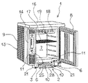
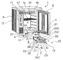
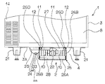
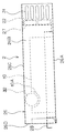
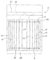
以下、図面に基づき本発明の実施形態を詳述する。図1は本発明を適用した実施例としての業務用冷蔵庫1の斜視図、図2は業務用冷蔵庫1から本発明の蒸発装置2を取り外した状態の分解斜視図、図3は業務用冷蔵庫1の蒸発装置2部分の正面図、図4は蒸発装置2の側面図、図5は蒸発装置2の平面図、図6は蒸発板10・・と接続部材5の分解斜視図である。
【0022】
冷蔵庫1は例えばホテルやレストラン、ファーストフードショップなどの厨房に設置される業務用冷蔵庫であり、各図において3は前方に開口する断熱箱体から構成された本体である。この本体3内には貯蔵室7が形成されている。また、本体3の前面右側には扉8が回動自在に枢支されており、この扉8により貯蔵室7の前面開口は開閉自在に閉塞される。
【0023】
更に、本体3の左側には機械室9が構成されており、この機械室9内には冷却装置を構成する図示しない圧縮機や凝縮器13が配設される。尚、凝縮器13は機械室9の周囲を囲繞するように配設されている。また、14はこの機械室9の前面を開閉するパネルである。また、本体3の天面にはステンレス製のトップテーブル16が取り付けられ、機械室9の上方まで覆っている。
【0024】
一方、本体3の貯蔵室7内には網棚17が架設されると共に、その上部は仕切板18により区画され、この仕切板18内には前記冷却装置を構成する図示しない冷却器と庫内送風ファン19が配設される。そして、冷却器と熱交換した冷気は庫内送風ファン19により貯蔵室7内に循環され、所定の冷蔵或いは冷凍温度に維持される。
【0025】
他方、本体3の下面3A四隅には所定高さ寸法の台脚21・・・が取り付けられており、この台脚21・・・によって下面3Aの下側には後述する蒸発装置などを配設するための下部空間4が形成されている。また、本体3の下面3A前部左右には取付板6、6が設けられており、これら取付板6には図示しない台下ガードが着脱自在に取り付けられ、下部空間4の前方を隠蔽する構成とされている。
【0026】
更に、本体3の下面3Aには前記各取付板6、6の内側において支持レール11、11が左右に位置して前後にそれぞれ延在し、取り付けられており、その前端には手指にて締緩可能な化粧ビス12、12が螺合するビス孔が形成された被取付面11A、11Aが前方に向けて形成されている。
【0027】
また、下面3A前部からは前記冷却器下側の図示しない露受皿及び貯蔵室7内に連通し、それらからのドレン水を排出するためのドレンホース23と、後述する送風ファン22に通電するための本体側給電線24が下部空間4にそれぞれ引き出されており、本体側給電線24の先端にはカプラ24Aが取り付けられている。
【0028】
一方、2は蒸発装置であり、例えば鋼板製の受け部材26と、この受け部材26の後部に形成されたファンケース27と、このファンケース27内に取り付けられた軸流ファンから成る送風ファン22と、受け部材26に挿脱自在に保持される樹脂製或いは鋼板製の蒸発皿28と、この蒸発皿28内に配置された蒸発板10・・・などから構成されている。
【0029】
受け部材26は底面26Aと、左右側面26B、26Bと、この左右側面26B、26Bの上端を直角に内側に折曲して形成されたフランジ26C、26Cと、各フランジ26C、26Cの前端において前方に向けて形成された取付面26D、26Dとから成り、各取付面26D、26Dには前記化粧ビス12、12が螺合或いは挿通可能なビス孔が形成されている。
【0030】
前記ファンケース27は係る受け部材26の奥部(後部)内側に固定されており、前後に開口して内部の送風ファン22を前後に露出させている。このとき、ファンケース27の下端は受け部材26の底面26Aよりも離間し、浮いた状態で取り付けられている。また、ファンケース27より後方の左右側面26B、26Bにはスリット31・・が穿設されている。
【0031】
更に、左側面26Bの前部上側には透孔32が穿設されており、この透孔32は前記ドレンホース23が通過可能な寸法とされている。また、前記送風ファン22から引き出されたファン側給電線33は左側面26Bの外側前部に引き回され、その先端にはカプラ33Aが取り付けられている。
【0032】
また、前記蒸発皿28は上方に開放した矩形皿状を呈しており、ファンケース27よりも前方の受け部材26の底面26A上に前方から挿脱自在に載置される寸法とされている。そして、この蒸発皿28内には蒸発板10が複数枚配置される。
【0033】
この蒸発板10は、繊維織布や多孔質プラスチック材などの給水性の良い材料を長方形板状に成形して構成されており、前記送風ファン22の送風方向である前後方向に向け、左右に所定の間隔を存して設けられるが、その際、軸流ファンである送風ファン22による送風量の多い左右側部は密に、中央部は疎に配置される(図5参照)。
【0034】
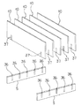
更に、係る各蒸発板10・・の間隔は接続部材5、5によって保持されている。この接続部材5は蒸発板10同様の吸水性の良い材料にて構成されており、図6に示す如く板状を呈した上縁には前記蒸発板10・・の間隔に合致した間隔(図では分かり易くするために等間隔で示している)で切込36・・が形成されている。
【0035】
一方、各蒸発板10の下縁前後にも切込37、37が形成されており、これら接続部材5、5の切込36・・に各蒸発板10の切込37、37を着脱自在に嵌合接続させることによって、蒸発板10・・・と接続部材5、5は組み立てられている。この状態で、各蒸発板10・・・は相互に前述の間隔を保持される。
【0036】
以上の構成で、本発明の蒸発装置2を本体3に組み付ける際には、蒸発皿28が載置された状態で、受け部材26のフランジ26C、26C後端を前方から支持レール11、11の前端に摺動自在に載置し、そのまま奥方に押し込んで行く。尚、このとき前記台下ガードは撤去しておく。やがて受け部材26の取付面26D、26Dが支持レール11、11の被取付面11A、11Aに当接すると受け部材26はそれ以上押し込めなくなる。
【0037】
この状態で受け部材26は下部空間4の所定位置に配置されると共に、取付面26Dのビス孔と被取付面11Aのビス孔とは合致する。そして、前記化粧ビス12、12を前方から前記ビス孔に着脱自在に螺合させることにより、受け部材26を本体3に固定する。
【0038】
次ぎに、ドレンホース23を透孔32から受け部材26内に引き込み、蒸発皿28上に開口させる。このとき、透孔32の側方に対応する位置の蒸発板10の前部上縁に図4の如く半円状の切欠10Aを形成しておき、引き込まれたドレンホース23をこの切欠10A上に載置するようにすれば、蒸発板10の高さ寸法を拡大して、蒸発板10の表面積を拡張し、ドレン水の蒸発能力を向上させることができるようになる。
【0039】
次ぎに、本体側給電線24のカプラ24Aとファン側給電線33のカプラ33Aを下面3Aの前部において接続し、組み付けを完了する。この状態で、前記冷却器或いは貯蔵室7からのドレン水はドレンホース23内を伝って蒸発皿28内に流入し、貯留される。前記蒸発板10・・及び接続部材5、5は蒸発皿28内に貯留されたドレン水に浸漬されるかたちとなるので、ドレン水は蒸発板10・・及び接続部材5、5に吸収される。
【0040】
吸収されたドレン水は毛管現象によりドレン水上に露出している部分に移動する。一方、送風ファン22は給電されて回転し、前方から空気を吸引して後方に排気する。これにより、ドレン水上に露出している部分の蒸発板10・・には通風が行われ、そこに移動して来たドレン水は当該部分の蒸発板10・・表面から蒸散される。
【0041】
このとき、送風ファン22による送風量の多い左右両側部は蒸発板10が密に配設されているので、蒸発板全体の枚数を増やすこと無く、蒸発板10表面への通風量を増大させ、蒸発処理能力を向上させることができるようになる。
【0042】
次ぎに、前記送風ファン22が故障した際には、前記台下ガードを取り外した状態で、前部に位置するドレンホース23を受け部材26から引き抜くと共に、各給電線24、33のカプラ24A、33Aを外した後、化粧ビス12、12を手指で緩めて取り外し、受け部材26を手前側に引き出すことにより、蒸発装置2は本体3から取り外すことができる。
【0043】
以上の構成により本発明の蒸発装置2では、冷蔵庫1を組み立てる際の本体3への組み付け、及び、送風ファン22のメンテナンスを行う際の取り外しを前方から極めて容易に行えるようになる。これにより、冷蔵庫1の組立作業性及び蒸発装置2のメンテナンス作業性の著しい向上を図ることができるようになる。
【0044】
また、各蒸発板10・・と接続部材5、5は容易に分解することができるので、蒸発板10の汚れた場合にも容易に清掃することができるようになる。特に、接続部材5、5も給水性の良い材料にて構成したので、この接続部材5、5からもドレン水を吸収することができるようになり、蒸発処理能力が一層向上する。
【0045】
更に、ファンケース27を受け部材26底面26Aより離間して設けたので、蒸発皿28から受け部材26にドレン水が溢出した場合にも、ファンケース27が浸水することが無くなる。これにより、送風ファン22の水没による故障を未然に回避することができるようになる。
【0046】
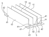
次ぎに、図7は蒸発板10及び接続部材5、5の他の実施例を示している。この場合、蒸発板10には前述同様の素材にて形成されているが、前述の如き切込は形成されていない。一方、接続部材5は水に浮く比重の小さいプラスチック材料などにて成形されており、一側縁には相互に対向する複数対の腕41、41・・が形成されており、各腕41、41間に前述同様の間隔を存して複数の挟持部42・・が構成されている。
【0047】
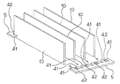
各腕部41、41は先端部が相互に近接するように鉤状に屈曲しており(図9)、且つ、近接する腕部41、41の先端間の間隔は蒸発板10の板厚よりも若干小さく構成されている。そして、前後一対の接続部材5を対向させ、各挟持部42・・・内に蒸発板10の前後縁を挿入し、各腕41、41間に着脱自在に挟持させることにより、蒸発板10・・・と接続部材5、5は組み立てられる。
【0048】
このように、蒸発板10を複数枚並設して接続部材5、5により相互に着脱自在に接続する構成としたので、前述同様に各蒸発板10・・を容易に分解することが可能となり、蒸発板10の清掃作業性が著しく向上する。特に、接続部材5には複数の挟持部42・・を形成し、各挟持部42・・内に各蒸発板10・・を挟持させる構成としたので、蒸発板10に切込を成形すること無く、接続部材5、5により保持することが可能となり、生産コストの削減を図ることができるようになる。
【0049】
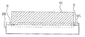
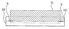
また、接続部材5を水に浮く材料にて構成したので、蒸発板10・・と接続部材5、5の組立体は、蒸発皿28内のドレン水中に下端の一部を浸漬した状態で浮くかたちとなる。従って、図10の如く蒸発皿28内のドレン水位WLが上昇した場合でも、或いは、図11の如くドレン水位WLが低下した場合にも、蒸発板10の殆どの部分はドレン水上に露出し(各図にハッチングで示す)、且つ、その寸法も略一定となる。
【0050】
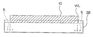
ここで、接続部材5を比重の重い部材にて構成すると、図12に示す如くドレン水位WLが上昇しても、接続部材5は浮くことができずに蒸発皿28内底部に沈むことになる。そのため、蒸発板10の殆どの部分は蒸発皿28内に水没してしまい、ドレン水上に露出する蒸発板10の寸法(図12にハッチングで示す)は著しく小さくなってしまうが、この実施例によれば前述の如く蒸発皿28内のドレン水位WLに係わらず、ドレン水上に露出する蒸発板10の寸法を維持することができるようになる。これにより、蒸発板10の蒸発表面積を確保し、蒸発能力の向上と安定化を図ることができるよになる。
【0051】
尚、実施例では業務用冷蔵庫に本発明を適用したが、それに限らず、家庭用冷蔵庫やショーケースなどに適用しても本発明は有効である。
【0052】
【発明の効果】
以上詳述した如く本発明によれば、冷蔵庫本体に取り付けられる受け部材と、この受け部材奥部に設けられたファンケース内に配設された送風ファンと、受け部材に保持され、前方より挿脱自在とされた蒸発皿と、この蒸発皿内に配置された給水性の良い蒸発板とを備え、蒸発皿上に臨んで冷蔵庫本体からのドレンホースが引き込まれるドレン水蒸発装置において、受け部材を冷蔵庫本体に前方より着脱自在に取り付けると共に、ドレンホースの引き込み位置及び送風ファンへの給電線の接続位置を受け部材の前部に配置した構造としたので、冷蔵庫を組み立てる際の冷蔵庫本体への組み付け、及び、送風ファンなどのメンテナンスを行う際の取り外しを極めて容易に行えるようになる。これにより、冷蔵庫の組立作業性及びドレン水蒸発装置のメンテナンス作業性の著しい向上を図ることができるようになるものである。
【0053】
請求項2の発明によれば、上記に加えてファンケースを受け部材底面より離間して設けたので、蒸発皿から受け部材にドレン水が溢出した場合にも、ファンケースが浸水することが無くなる。これにより、送風ファンの水没による故障を未然に回避することができるようになるものである。
【0054】
請求項3の発明によれば、上記各発明に加えて蒸発板の上部には切欠を形成し、この切欠に引き込まれたドレンホースを載置するようにしたので、蒸発板の高さ寸法を拡大することが可能となる。これにより、蒸発板の表面積を拡張し、ドレン水の蒸発能力を一層向上させることができるようになるものである。
【0055】
請求項4の発明によれば、上記各発明に加えて蒸発板を複数枚並設して接続部材により相互に着脱自在に接続する構成としたので、各蒸発板を容易に分解することが可能となり、蒸発板の清掃作業性が著しく向上する。特に、接続部材を水に浮く材料にて構成したので、蒸発皿内のドレン水位に係わらず、ドレン水上に露出する蒸発板の寸法を維持することができるようになる。これにより、蒸発板の蒸発表面積を確保し、蒸発能力の向上と安定化を図ることができるよになるものである。
【0056】
請求項5の発明によれば、請求項1、請求項2又は請求項3の発明に加えて、蒸発板を複数枚並設して接続部材により相互に着脱自在に接続する構成としたので、各蒸発板を容易に分解することが可能となり、蒸発板の清掃作業性が著しく向上する。特に、接続部材には複数の挟持部を形成し、各挟持部内に各蒸発板を挟持させる構成としたので、蒸発板を格別な形状に成形すること無く、接続部材により保持することが可能となり、生産コストの削減を図ることができるようになるものである。
【0057】
請求項6の発明によれば、請求項1、請求項2又は請求項3の発明に加えて、蒸発板を複数枚並設して接続部材により相互に着脱自在に接続する構成としたので、各蒸発板を容易に分解することが可能となり、蒸発板の清掃作業性が著しく向上する。特に、接続部材も給水性の良い材料にて構成したので、この接続部材からもドレン水を吸収することができるようになり、蒸発処理能力を一層向上させることができるようになるものである。
【0058】
請求項7の発明によれば、請求項1、請求項2又は請求項3の発明に加えて、蒸発板を送風ファンの送風方向に向けて複数枚並設すると共に、送風ファンによる送風量の多い箇所に密に配置したので、蒸発板を全体の枚数を増やすこと無く、蒸発板表面への通風量を増大させ、蒸発処理能力を一層向上させることができるようになるものである。
【図面の簡単な説明】
【図1】本発明を適用した実施例としての業務用冷蔵庫の斜視図である。
【図2】業務用冷蔵庫から本発明の蒸発装置を取り外した状態の分解斜視図である。
【図3】業務用冷蔵庫の蒸発装置部分の正面図である。
【図4】本発明の蒸発装置の側面図である。
【図5】本発明の蒸発装置の平面図である。
【図6】蒸発板と接続部材の分解斜視図である。
【図7】他の実施例の蒸発板と接続部材の斜視図である。
【図8】図7の蒸発板と接続部材の分解斜視図である。
【図9】図7の接続部材の平面図である。
【図10】蒸発皿内のドレン水位が上昇した場合の図7の蒸発板及び接続部材の状態を説明する図である。
【図11】蒸発皿内のドレン水位が低下した場合の図7の蒸発板及び接続部材の状態を説明する図である。
【図12】比重の重い接続部材を使用した際に蒸発皿内のドレン水位が上昇した場合の蒸発板及び接続部材の状態を説明する図である。
【符号の説明】
1 業務用冷蔵庫
2 蒸発装置
5 接続部材
10 蒸発板
12 化粧ビス
22 送風ファン
23 ドレンホース
24、33 給電線
26 受け部材
27 ファンケース
28 蒸発皿
32 透孔
42 挟持部[0001]
BACKGROUND OF THE INVENTION
The present invention relates to a drain water evaporation device for evaporating drain water from a refrigerator cooler or a storage room.
[0002]
[Prior art]
Conventionally, this type of commercial / household refrigerator has an evaporating dish supported on a support member formed on the main body side so as to be detachable, as disclosed in, for example, Japanese Patent Laid-Open No. 6-159907 (F25D21 / 14), A structure in which a drain hose is drawn on the evaporating dish to drain the drain water from the cooler or the storage chamber, and the evaporating dish is blown by a blower fan provided in the machine chamber to evaporate the drain water. It is said that.
[0003]
In the above publication, the evaporation surface area is enlarged by providing a plurality of evaporation plates formed in a plate shape with a material having good water supply such as a fiber woven cloth or porous plastic material in the evaporation dish, and drain water is supplied to the evaporation plates. Evaporation capacity is improved by absorbing and diverging during blowing. Furthermore, in recent years, an evaporation apparatus has also been developed in which the blower fan and the receiving member that receives the evaporating dish are integrated into a unit, and this unit is attached to the refrigerator body.
[0004]
[Problems to be solved by the invention]
However, since such a conventional evaporation device could not be easily attached to or removed from the refrigerator body, the maintenance work at the time of assembly or when the blower fan fails becomes extremely troublesome. It was.
[0005]
In addition, a plurality of evaporation plates are usually arranged side by side, connected to each other via a connection member, and finally stopped by a stapler. Therefore, if the plate is contaminated by dust contained in the drain water, it can be cleaned. It was extremely difficult. Furthermore, since the conventional structure has only a structure in which the evaporation plates are simply arranged in parallel, there is a limit to the improvement of the evaporation ability.
[0006]
The present invention has been made to solve the conventional technical problems, and provides a drain water evaporation device for a refrigerator that improves assembly and maintenance workability and further improves evaporation capability. It is.
[0007]
[Means for Solving the Problems]
The drain water evaporator according to the present invention includes a receiving member attached to the refrigerator main body, a blower fan disposed in a fan case provided at the back of the receiving member, and the receiving member, and is detachable from the front. The evaporating dish and an evaporating plate with good water supply disposed in the evaporating dish are provided, and the drain hose from the refrigerator main body is drawn on the evaporating dish, and the receiving member is the refrigerator main body. In addition to being detachably attached to the front, the drain hose drawing-in position and the connection position of the power supply line to the blower fan are arranged at the front part of the member.
[0008]
According to the present invention, the receiving member attached to the refrigerator main body, the blower fan disposed in the fan case provided at the back of the receiving member, and the receiving member are held and can be inserted and removed from the front. In a drain water evaporation apparatus that includes an evaporating dish and an evaporating plate with good water supply disposed in the evaporating dish, the drain hose from the refrigerator body faces the evaporating dish, and the receiving member is placed in front of the refrigerator body. Since it has a structure in which the drain hose is pulled in and the connection position of the power supply line to the blower fan is placed at the front of the member, it is attached to the refrigerator body when assembling the refrigerator, and the air blower. The fan can be easily removed when performing maintenance. Thereby, the assembly workability | operativity of a refrigerator and the maintenance workability | operativity of a drain water evaporator can be improved significantly.
[0009]
The drain water evaporator of the refrigerator of the invention of
[0010]
According to the invention of
[0011]
According to a third aspect of the present invention, there is provided a drain water evaporation device for a refrigerator, wherein in each of the above inventions, a notch is formed in the upper portion of the evaporation plate, and a drain hose drawn into the notch is placed.
[0012]
According to the invention of
[0013]
According to a fourth aspect of the present invention, there is provided a drain water evaporation apparatus for a refrigerator. In each of the above inventions, a plurality of evaporation plates are arranged side by side and are detachably connected to each other by a connection member. It is composed.
[0014]
According to the invention of
[0015]
According to a fifth aspect of the present invention, there is provided a drain water evaporation device for a refrigerator according to the first, second or third aspect, wherein a plurality of evaporation plates are arranged in parallel and are detachably connected to each other by a connecting member. The connecting member is formed with a plurality of holding portions, and the respective evaporation plates are held in the holding portions.
[0016]
According to the invention of
[0017]
According to a sixth aspect of the present invention, there is provided a drain water evaporation apparatus for a refrigerator according to the first, second, or third aspect, wherein a plurality of evaporation plates are arranged side by side and are detachably connected to each other by a connecting member. The connecting member is made of a material with good water supply.
[0018]
According to the invention of
[0019]
A drain water evaporation device for a refrigerator according to a seventh aspect of the invention is the invention according to the first, second, or third aspect, wherein a plurality of evaporation plates are arranged in parallel in the blowing direction of the blower fan, and the blower fan is used. It is densely arranged in a location with a large air flow.
[0020]
According to the invention of
[0021]
DETAILED DESCRIPTION OF THE INVENTION
Hereinafter, embodiments of the present invention will be described in detail with reference to the drawings. FIG. 1 is a perspective view of a
[0022]
The
[0023]
Further, a
[0024]
On the other hand, a
[0025]
On the other hand, pedestals 21 of predetermined height are attached to the four corners of the
[0026]
Further, support rails 11 and 11 are attached to the
[0027]
Further, the front surface of the
[0028]
On the other hand,
[0029]
The receiving
[0030]
The
[0031]
Further, a through
[0032]
Further, the evaporating
[0033]
The evaporating
[0034]
Further, the interval between the
[0035]
On the other hand, cuts 37, 37 are also formed before and after the lower edge of each
[0036]
With the above configuration, when the
[0037]
In this state, the receiving
[0038]
Next, the drain hose 23 is drawn into the receiving
[0039]
Next, the coupler 24A of the main body
[0040]
The absorbed drain water moves to a portion exposed on the drain water by capillary action. On the other hand, the
[0041]
At this time, since the
[0042]
Next, when the
[0043]
With the above configuration, in the
[0044]
Further, since each of the
[0045]
Furthermore, since the
[0046]
Next, FIG. 7 shows another embodiment of the
[0047]
Each
[0048]
As described above, since a plurality of
[0049]
Further, since the connecting
[0050]
Here, if the
[0051]
In the embodiment, the present invention is applied to a commercial refrigerator. However, the present invention is not limited to this, and the present invention is effective when applied to a household refrigerator or a showcase.
[0052]
【The invention's effect】
As described above in detail, according to the present invention, the receiving member attached to the refrigerator main body, the blower fan disposed in the fan case provided in the back of the receiving member, and the receiving member are inserted from the front. In a drain water evaporation apparatus, which includes an evaporating dish made removable and an evaporating plate with good water supply disposed in the evaporating dish, and a drain hose from the refrigerator body is drawn on the evaporating dish. Detachably attached to the refrigerator body from the front, and a structure in which the drain hose pull-in position and the connection position of the power supply line to the blower fan are arranged at the front of the member, so that the refrigerator body when assembling the refrigerator Assembling and detaching when performing maintenance such as a blower fan can be performed very easily. Thereby, the assembly workability | operativity of a refrigerator and the maintenance workability | operativity of a drain water evaporator can be improved significantly.
[0053]
According to the invention of
[0054]
According to the invention of
[0055]
According to the invention of
[0056]
According to the invention of
[0057]
According to the invention of
[0058]
According to the invention of
[Brief description of the drawings]
FIG. 1 is a perspective view of a commercial refrigerator as an embodiment to which the present invention is applied.
FIG. 2 is an exploded perspective view of the commercial refrigerator with the evaporation apparatus of the present invention removed.
FIG. 3 is a front view of an evaporator part of a commercial refrigerator.
FIG. 4 is a side view of the evaporation apparatus of the present invention.
FIG. 5 is a plan view of the evaporation apparatus of the present invention.
FIG. 6 is an exploded perspective view of an evaporation plate and a connection member.
FIG. 7 is a perspective view of an evaporation plate and a connecting member according to another embodiment.
8 is an exploded perspective view of the evaporation plate and the connection member of FIG.
9 is a plan view of the connection member of FIG. 7. FIG.
10 is a diagram for explaining a state of the evaporation plate and the connection member in FIG. 7 when the drain water level in the evaporation dish rises.
11 is a view for explaining the state of the evaporation plate and the connecting member in FIG. 7 when the drain water level in the evaporating dish is lowered.
FIG. 12 is a diagram for explaining the state of the evaporation plate and the connecting member when the drain water level in the evaporating dish rises when a connecting member having a high specific gravity is used.
[Explanation of symbols]
DESCRIPTION OF
Claims (7)
前記受け部材を前記冷蔵庫本体に前方より着脱自在に取り付けると共に、前記ドレンホースの引き込み位置及び前記送風ファンへの給電線の接続位置を前記受け部材の前部に配置したことを特徴とする冷蔵庫のドレン水蒸発装置。A receiving member attached to the refrigerator main body, a blower fan disposed in a fan case provided at the back of the receiving member, an evaporating dish held by the receiving member and detachable from the front, A drain water evaporation device provided with an evaporating plate with good water supply disposed in the evaporating dish, and facing the evaporating dish and a drain hose from the refrigerator body being drawn in,
The receiving member is detachably attached to the refrigerator main body from the front, and the drawing position of the drain hose and the connecting position of the power supply line to the blower fan are arranged in the front part of the receiving member. Drain water evaporator.
Priority Applications (2)
| Application Number | Priority Date | Filing Date | Title |
|---|---|---|---|
| JP02610897A JP3649838B2 (en) | 1997-01-24 | 1997-01-24 | Drain water evaporator for refrigerator |
| KR1019990047674A KR100296898B1 (en) | 1996-07-29 | 1999-10-30 | Chilling cabinet |
Applications Claiming Priority (1)
| Application Number | Priority Date | Filing Date | Title |
|---|---|---|---|
| JP02610897A JP3649838B2 (en) | 1997-01-24 | 1997-01-24 | Drain water evaporator for refrigerator |
Publications (2)
| Publication Number | Publication Date |
|---|---|
| JPH10205982A JPH10205982A (en) | 1998-08-04 |
| JP3649838B2 true JP3649838B2 (en) | 2005-05-18 |
Family
ID=12184406
Family Applications (1)
| Application Number | Title | Priority Date | Filing Date |
|---|---|---|---|
| JP02610897A Expired - Fee Related JP3649838B2 (en) | 1996-07-29 | 1997-01-24 | Drain water evaporator for refrigerator |
Country Status (1)
| Country | Link |
|---|---|
| JP (1) | JP3649838B2 (en) |
Families Citing this family (4)
| Publication number | Priority date | Publication date | Assignee | Title |
|---|---|---|---|---|
| JP5486841B2 (en) * | 2009-05-21 | 2014-05-07 | 三菱電機株式会社 | Delon cup type heat exchanger |
| JP5816841B2 (en) * | 2011-02-28 | 2015-11-18 | パナソニックIpマネジメント株式会社 | Drain water evaporator for cooling device |
| JP6298693B2 (en) * | 2014-04-10 | 2018-03-20 | ダイニック株式会社 | Transpiration plate unit |
| JP2016188739A (en) * | 2015-03-30 | 2016-11-04 | 三菱電機株式会社 | Evaporation plate assembly of showcase, drain water evaporator, and showcase |
Family Cites Families (7)
| Publication number | Priority date | Publication date | Assignee | Title |
|---|---|---|---|---|
| JPS4945516Y2 (en) * | 1971-04-20 | 1974-12-12 | ||
| JPS63127067A (en) * | 1986-11-17 | 1988-05-30 | 株式会社東芝 | Refrigerator |
| JPH01181080A (en) * | 1988-01-14 | 1989-07-19 | Hitachi Ltd | Drain evaporating device for refrigerator |
| JP2645919B2 (en) * | 1991-03-18 | 1997-08-25 | 三洋電機株式会社 | Drain water evaporator |
| JPH04313673A (en) * | 1991-04-12 | 1992-11-05 | Toshiba Corp | Refrigerator |
| JP3253378B2 (en) * | 1992-11-30 | 2002-02-04 | 三洋電機株式会社 | refrigerator |
| JPH09243234A (en) * | 1996-03-05 | 1997-09-19 | Hoshizaki Electric Co Ltd | Defrosted drain evaporator in cooling storage chamber |
-
1997
- 1997-01-24 JP JP02610897A patent/JP3649838B2/en not_active Expired - Fee Related
Also Published As
| Publication number | Publication date |
|---|---|
| JPH10205982A (en) | 1998-08-04 |
Similar Documents
| Publication | Publication Date | Title |
|---|---|---|
| CN1277093C (en) | Defrosting water draining device for refrigerator | |
| JP3649838B2 (en) | Drain water evaporator for refrigerator | |
| US2591178A (en) | Apparatus for aging meats and storing vegetables | |
| JP3667538B2 (en) | Ice machine | |
| JP2001201108A (en) | Outdoor unit of air conditioner | |
| JP2001201241A (en) | Refrigerated showcase | |
| JP2005274088A (en) | Evaporating device | |
| CN219346967U (en) | Evaporation device and cold and hot equipment | |
| KR100296898B1 (en) | Chilling cabinet | |
| JP3863697B2 (en) | Refrigerator | |
| JPH06159907A (en) | Refrigerator | |
| JPH1019449A (en) | Cooling storage | |
| JP4504796B2 (en) | Cooling storage | |
| CN112197491A (en) | Wardrobe | |
| JP2001208462A (en) | Showcase | |
| JPH11237165A (en) | refrigerator | |
| KR980010287A (en) | Drain water evaporator in cold storage and refrigerator | |
| JP3457648B2 (en) | Showcase cleaning equipment | |
| JPH03294776A (en) | Cool showcase for flower | |
| JPH0743205B2 (en) | Cooling showcase | |
| JP3550552B2 (en) | refrigerator | |
| JP5633974B2 (en) | refrigerator | |
| JP5912796B2 (en) | Showcase | |
| JPH04260776A (en) | Drain evaporator | |
| JP2024115145A (en) | Cooling Storage |
Legal Events
| Date | Code | Title | Description |
|---|---|---|---|
| A977 | Report on retrieval |
Free format text: JAPANESE INTERMEDIATE CODE: A971007 Effective date: 20040901 |
|
| TRDD | Decision of grant or rejection written | ||
| A01 | Written decision to grant a patent or to grant a registration (utility model) |
Free format text: JAPANESE INTERMEDIATE CODE: A01 Effective date: 20050201 |
|
| A61 | First payment of annual fees (during grant procedure) |
Free format text: JAPANESE INTERMEDIATE CODE: A61 Effective date: 20050216 |
|
| FPAY | Renewal fee payment (event date is renewal date of database) |
Free format text: PAYMENT UNTIL: 20090225 Year of fee payment: 4 |
|
| FPAY | Renewal fee payment (event date is renewal date of database) |
Free format text: PAYMENT UNTIL: 20090225 Year of fee payment: 4 |
|
| FPAY | Renewal fee payment (event date is renewal date of database) |
Free format text: PAYMENT UNTIL: 20100225 Year of fee payment: 5 |
|
| FPAY | Renewal fee payment (event date is renewal date of database) |
Free format text: PAYMENT UNTIL: 20110225 Year of fee payment: 6 |
|
| LAPS | Cancellation because of no payment of annual fees |