JP3649831B2 - Liquid ejector - Google Patents
Liquid ejector Download PDFInfo
- Publication number
- JP3649831B2 JP3649831B2 JP35573596A JP35573596A JP3649831B2 JP 3649831 B2 JP3649831 B2 JP 3649831B2 JP 35573596 A JP35573596 A JP 35573596A JP 35573596 A JP35573596 A JP 35573596A JP 3649831 B2 JP3649831 B2 JP 3649831B2
- Authority
- JP
- Japan
- Prior art keywords
- cylinder
- stem
- short tube
- fitted
- guide short
- Prior art date
- Legal status (The legal status is an assumption and is not a legal conclusion. Google has not performed a legal analysis and makes no representation as to the accuracy of the status listed.)
- Expired - Lifetime
Links
- 239000007788 liquid Substances 0.000 title claims description 32
- XLYOFNOQVPJJNP-UHFFFAOYSA-N water Substances O XLYOFNOQVPJJNP-UHFFFAOYSA-N 0.000 claims description 9
- 230000002093 peripheral effect Effects 0.000 claims description 6
- 239000012530 fluid Substances 0.000 claims description 2
- 230000035699 permeability Effects 0.000 claims description 2
- 238000009423 ventilation Methods 0.000 claims 1
- 238000007789 sealing Methods 0.000 description 3
- 239000000758 substrate Substances 0.000 description 3
- 230000000694 effects Effects 0.000 description 2
- 238000005452 bending Methods 0.000 description 1
- 238000000605 extraction Methods 0.000 description 1
Images
Classifications
-
- B—PERFORMING OPERATIONS; TRANSPORTING
- B05—SPRAYING OR ATOMISING IN GENERAL; APPLYING FLUENT MATERIALS TO SURFACES, IN GENERAL
- B05B—SPRAYING APPARATUS; ATOMISING APPARATUS; NOZZLES
- B05B11/00—Single-unit hand-held apparatus in which flow of contents is produced by the muscular force of the operator at the moment of use
- B05B11/01—Single-unit hand-held apparatus in which flow of contents is produced by the muscular force of the operator at the moment of use characterised by the means producing the flow
- B05B11/10—Pump arrangements for transferring the contents from the container to a pump chamber by a sucking effect and forcing the contents out through the dispensing nozzle
- B05B11/1001—Piston pumps
Landscapes
- Closures For Containers (AREA)
- Containers And Packaging Bodies Having A Special Means To Remove Contents (AREA)
Description
【0001】
【発明の属する技術分野】
本発明は、縦形ポンプ式の液体噴出器に関する。
【0002】
【従来の技術】
特開平8‐268458号公報が示すように、容器体口頸部外面へ嵌合させる装着筒の上部内からシリンダを垂下すると共に、該シリンダ内からステム下端に筒状ピストンを、かつ上端にノズル付き押下げヘッドを、それぞれ有する作動部材を、シリンダ上端部に嵌着させたガイド短管内にステムを挿通させて起立し、該作動部材が上限に位置する状態にあっては、ガイド短管の内筒下端面が、ステムの下部外面に設けた上向き段部の外周面へ水密に接すると共に、作動部材下降により上記ガイド短管内面とステムとの間に設けた小間隙を通って、外気とシリンダ壁上部に穿設した外気吸入孔とが連通可能となし、
上記作動部材の上下動で容器体内液体をシリンダ内へ、シリンダ下端内へ弾性閉塞させて設けた吸込み弁を介して吸込み、該シリンダ内液体を吐出弁を介して上記押下げヘッドのノズルから噴出可能とした液体噴出器が知られている。
【0003】
又上記液体噴出器における、ガイド短管の内筒下端面とステム下部外面の上向き段部とによる、外気とシリンダ壁上部の外気吸入孔との間の外気流通路の開閉に代えて、ガイド短管とステムとの間へ、筒部下端に筒状シール筒を有するシール部材を、その筒部をステム外面へ摺動自在に嵌合させると共にガイド短管内面へ強制摺動可能に挿通させて上方へ起立し、かつ筒状シール筒をシリンダの上部内面へ嵌合させ、上記筒部の下端面とステム下部外面の上向き段部とで、上記外気流通路の開閉を行っている液体噴出器も知られている。
【0004】
【発明が解決しようとする課題】
上記従来例の液体噴出器は、気温の変化等で容器体内空気が膨張し、高圧化しても、シリンダ下端内の吸込み弁を弾性閉塞しておくことで、容器体内液体が作動部材内を通ってノズルから液垂れすることを防止できるようにしたものであるが、上記容器体内が更に高圧化すると、液面加圧により弾性に抗して吸込み弁体が押上げられることとなり、すると上記ノズルから液垂れすることとなる。
【0005】
本発明は、上記ガイド短筒の内筒下端面とステム下部外面の上向き段部とによる、又シール部材の筒部下端面と上記上向き段部とによる、外気流通路閉塞部分に、通水は不能であると共に、容器体内に発生した高圧気体は通過可能な微小通路を形成することで、既述従来の欠点を除去するものである。
【0006】
【課題を解決するための手段】
第1の手段として、容器体口頸部外面へ嵌合させる装着筒1の上部内からシリンダ2を垂下すると共に、該シリンダ内から、ステム32下端に筒状ピストン33を、かつ上端にノズル34付きの押下げヘッド35を、それぞれ有する作動部材31を、シリンダ上端部に嵌着させたガイド短管11内にステム32を挿通させて起立し、
該作動部材が上限に位置する状態にあっては、ガイド短管11の内筒15下端面が、ステム32の下部外面に設けた上向き段部38の上面へ水密に接すると共に、作動部材31下降により上記ガイド短管内筒15とステムとの間に設けた小間隙を通って外気とシリンダ壁の上部に穿設した外気吸入孔8とが連通可能となし、
上記作動部材の上下動で容器体内液体をシリンダ2内へ、シリンダ下端内へ弾性閉塞させて設けた吸込み弁27を介して吸込み、該シリンダ内液体を吐出弁36を介して上記押下げヘッド35のノズルから噴出可能とした液体噴出器において、
上記ガイド短管11の内筒15下端面とステムの上向き段部38上面とのいずれかの一方ないし双方に、上向き段部38上へ内筒下端面が圧接する状態で、通水不能でかつ通気性を有する微小通路41を形成した。
【0007】
第2の手段として、容器体口頸部外面へ嵌合させる装着筒1の上部内からシリンダ2を垂下すると共に、該シリンダ内から、ステム32下端に筒状ピストン33を、かつ上端にノズル34付きの押下げヘッド35を、それぞれ有する作動部材31を、シリンダ上端部に嵌着させたガイド短管11内にステム32を挿通させて起立し、
又上記ステム32外面へ摺動可能に嵌合させた筒部52の上部を、ガイド短管11内面へ強制摺動可能に挿通させて起立し、かつ筒部52下端に、シリンダ上端部内面へ嵌合する筒状シール筒53を付設したシール部材51を設け、
上記作動部材31が上限に位置する状態にあっては、上記シール部材の筒部52下端面がステム32の下部外面に設けた上向き段部38の外周縁へ水密に接すると共に、作動部材31下降により筒部52内面とステム32との間に設けた小間隙とシリンダ壁上部に穿設した外気吸入孔8とが連通可能となし、
上記作動部材31の上下動で容器体内液体をシリンダ内へ、シリンダ下端内へ弾性閉塞させて設けた吸込み弁27を介して吸込み、該シリンダ内液体を吐出弁を介して上記押下げヘッド35のノズルから噴出可能とした液体噴出器において、
上記シール部材の筒部52下端面とステムの上向き段部38上面とのいずれかの一方ないし双方に、上向き段部38上へ内筒下端面が圧接する状態で、通水不能でかつ通気性を有する微小通路41を形成した。
【0008】
【発明の実施の形態】
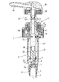
まず、図1が示す実施形態について説明すると、1は容器体口頸部外面へ嵌合させる装着筒で、該装着筒の上部内からシリンダ2を垂下している。該シリンダの下端部内には吸込み弁座3を付設し、かつシリンダ下端からは小径の吸上げパイプ嵌合筒4を垂下し、又該筒内へ上端部を嵌合させて吸上げパイプ5を垂下している。弁座上方のシリンダ下部内面には複数のリブ6を縦設し、かつ該リブ上部内面には上向き段部7を設けている。更にシリンダ壁上部には外気吸入孔8を穿設し、又シリンダ上端から起立する嵌合筒9にガイド短管11を回動不能に嵌着させている。
【0009】
ガイド短管11は、フランジ状頂板12外周から雄ねじ筒13を垂下して該雄ねじ筒を上記シリンダ上端の嵌合筒9外面へ、又フランジ状頂板の中間部から垂設した中筒14を嵌合筒9およびシリンダの上端部内面へ、それぞれ嵌合させ、更にフランジ状頂板12内周から内筒15を垂下させ、嵌合筒9と雄ねじ筒13とに設けた抜出し防止用の係合突条、および嵌合筒9と中筒14とに設けた回動防止用の縦突条とで、シリンダ2に対してガイド短管11が抜出しおよび回動不能に嵌合させている。
【0010】
上記シリンダ下部内には吸込み弁部材21を装着している。該部材は、上記上向き段部7上へ外周部を載置させた基板22下面から屈曲弾性バネ片23を垂下して該バネ片下端に付設した吸込み弁体24を吸込み弁座3へ着座させると共に、基板上面から、平面十字形状をなす棒状部25を起立し、その上端に上面開口の筒部26を付設している。
【0011】
シリンダ2内からは作動部材31を起立させている。該作動部材は、ステム32下端に筒状ピストン33を付設し、又ステム上端にノズル34付き押下げヘッド35を嵌着させており、ステム上方内には吐出弁36を有する。
【0012】
作動部材31は、吸込み弁部材21の基板22外周部とステム32の下端との間に介装されたコイルスプリング37で上方付勢されている。作動部材31はその付勢に抗して押下げ、又その付勢により上昇することで容器体内液体を吸込み弁27を介してシリンダ内へ吸込み、又該シリンダ内液体を吐出弁36を介してノズル34から噴出する。
【0013】
ステム32の下部外径は、上向き段部38を介してやや大外径に形成してあり、その上向き段部38の上面には既述ガイド短管11の内筒15下端面を水密に圧接させる。
【0014】
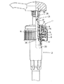
既述ガイド短管11は、図3が示すように形成する場合もある。該短管は、フランジ状頂板12の中間部から垂設した中筒14を、シリンダ上端の嵌合筒9外面へ、又内筒15を嵌合筒9およびシリンダの上部内面へ、それぞれ嵌合させ、嵌合筒9と中筒14とに抜出し防止用の係合突条を、又嵌合筒9と内筒15とに回動防止用の縦突条を、それぞれ付設している。内筒15上部は雌ねじ筒とし、かつその雌ねじ下方の筒部分からは下内方へ弾性筒16を垂下し、該弾性筒にステム32を挿通させている。
【0015】
尚その弾性筒16は、作動部材31を押下げ、押下げヘッド35から垂下するステム嵌合筒39を雌ねじ筒内へ螺合させたとき、ステム32より大外径としたステム嵌合筒39の下部外面へ弾性筒16が水密に接するよう設けている。
【0016】
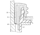
本発明にあっては、既述両実施形態において、ガイド短筒11の内筒15下端面とステム32の上向き段部38上面とのいずれかの一方ないし双方に、それ等両面が圧接する状態、つまり作動部材31がコイルスプリング37で押上げられた状態において、通水は不能であると共に、空気は通過可能な微小通路41を形成した。該微小通路は単数又は複数の凹溝で形成してもよく、又複数の凸リブを付設してそれ等凸リブ間に形成される隙間で形成してもよい。更に上記両面の一方ないし両面を梨地状の粗面に形成して、その粗面で微小通路41を形成してもよい。但しその微小通路は、液体の粘度が大であれば通り難く、又粘度が少なければ通過し易いから、容器体内に収納させる液体の粘度によってその微小通路の断面積を変えることが出来る。
【0017】
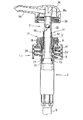
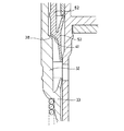
図4、図5が示す実施形態は、主としてステム32外面とガイド短管11との間にシール部材51を装着させた点で図1実施形態と相違するものである。該シール部材は、ステム32外面へ摺動可能に嵌合させた筒部52の上部を、ガイド短管11内面へ強制摺動可能に挿通させて起立し、かつ筒部52下端に、シリンダ上端部内面へ嵌合する筒状シール筒53を付設したものである。
【0018】
該シール部材は、作動部材上部が邪魔とならないよう、作動部材を押下げして押下げヘッド35の周壁をガイド短管11外面へ螺合させると、ステム嵌合筒39の上部外面に付設したリブ39a 下端がシール部材の筒部52上端を押下げ、該押下げにより筒状シール筒53が外気吸入孔8を閉塞し、又図示のように押下げヘッド35を螺脱すると、作動部材31がスプリングによる上方付勢で押上げられ、するとステム32下部に設けた上向き段部38がシール部材51の筒部52下端面を押上げることで、該シール部材はガイド短管11に対して上昇し、該上昇で筒状シール筒53は外気吸入孔8上方まで押上げられる。
【0019】
該実施形態の場合は、既述微小通路41を、上記シール部材筒部52の下端面とステムの上向き段部38上面とのいずれかの一方ないしは双方に付形すればよい。
既述構成とすることで、気温の変化等で容器体内が高圧化したとき、容器体内の高圧空気は外気吸入孔8、微小通路41、およびガイド短管11とステム32との間、又はシール部材51の筒部52とステム32との間を通って外気中に放出され、他方吸込み弁27は弾性閉塞されているため、上記容器体内液体がシリンダ2内を通ってノズル34から液垂れすることはない。
【0020】
【発明の効果】
請求項1記載の本発明は、既述構成の液体噴出器において、ガイド短管11の内筒14下端面とステム32の上向き段部38上面とのいずれかの一方ないし双方に、上向き段部38上へ内筒15下端面が圧接する状態で通水は不能であると共に空気は通過可能な微小通路41を形成したから、容器体内が気温の変化等で高圧化しても、該高圧空気はシリンダ上部に設けた外気吸入孔8、微小通路41、ガイド短管11とステム32との間を通って外気中に放出されることとなり、よって従来のように容器体内に生じた高圧空気が液体を押下げ、吸込み弁、シリンダ、作動部材内を通ってノズル34から液体を漏出させることを防止できる。又容器が倒れても、上記微小通路41は通水不能でかつ吸込み弁27は弾性閉塞されているから、ガイド短管11とステム32との間、およびノズル34からのいずれからの漏水も防止することが出来る。
【0021】
請求項2記載の発明は、請求項1記載発明のガイド短管内筒15の下端とステムの上向き段部38上面との圧接を、ガイド短管内面に嵌合させたシール部材51の筒部52下端とステムの上向き段部38上面との圧接に代え、該圧接筒所へ微小通路41を形成したから、請求項1記載発明の場合と同様の効果を有する。
【図面の簡単な説明】
【図1】 本発明液体噴出器の断面図である。
【図2】 図1要部の拡大図である。
【図3】 実施形態を異にして示す、液体噴出器の断面図である。
【図4】 更に実施形態を異にして示す、液体噴出器の断面図である。
【図5】 図4要部の拡大図である。
【符号の説明】
11…ガイド短管 31…作動部材
32…ステム 38…上向き段部
51…シール部材 52…筒部[0001]
BACKGROUND OF THE INVENTION
The present invention relates to a vertical pump type liquid ejector.
[0002]
[Prior art]
As shown in Japanese Patent Laid-Open No. 8-268458, a cylinder is suspended from the upper part of a mounting cylinder to be fitted to the outer surface of the container body neck and neck, a cylindrical piston is disposed at the lower end of the stem, and a nozzle is disposed at the upper end. When the operating member having the push-down head is erected by inserting the stem into the guide short tube fitted to the upper end of the cylinder and the operating member is positioned at the upper limit, The lower end surface of the inner cylinder is in watertight contact with the outer peripheral surface of the upward stepped portion provided on the lower outer surface of the stem, and passes through a small gap provided between the inner surface of the guide short tube and the stem as the operating member descends. The outside air suction hole drilled in the upper part of the cylinder wall can communicate,
The liquid in the container is sucked into the cylinder by the vertical movement of the operating member through a suction valve that is elastically closed into the lower end of the cylinder, and the liquid in the cylinder is ejected from the nozzle of the push-down head through the discharge valve. Liquid ejectors that make possible are known.
[0003]
Further, in the liquid ejector, instead of opening and closing the external air flow path between the outside air and the outside air suction hole in the cylinder wall upper portion by the lower end surface of the inner tube of the guide short tube and the upward stepped portion on the lower surface of the stem, the guide short A seal member having a cylindrical seal cylinder at the lower end of the cylinder part is inserted between the pipe and the stem so that the cylinder part is slidably fitted to the outer surface of the stem and slidably inserted into the inner surface of the guide short pipe. A liquid ejector that rises upward, fits a cylindrical seal cylinder to the upper inner surface of the cylinder, and opens and closes the external airflow passage between the lower end surface of the cylindrical portion and the upward stepped portion of the stem lower outer surface Is also known.
[0004]
[Problems to be solved by the invention]
In the above-described conventional liquid ejector, even if the air in the container expands due to a change in temperature or the like and the pressure increases, the liquid in the container passes through the working member by elastically closing the suction valve in the lower end of the cylinder. However, when the pressure inside the container is further increased, the suction valve body is pushed up against the elasticity by liquid level pressurization. It will be dripping from.
[0005]
According to the present invention, water cannot pass through the outer airflow passage blockage portion formed by the lower end surface of the inner tube of the guide short tube and the upward stepped portion on the outer surface of the lower portion of the stem, and by the lower end surface of the cylindrical portion of the seal member and the upward stepped portion. In addition, the above-described conventional drawbacks are eliminated by forming a micro passage through which the high-pressure gas generated in the container can pass.
[0006]
[Means for Solving the Problems]
As a first means, the
In the state where the operating member is located at the upper limit, the lower end surface of the
The liquid in the container is sucked into the
In the state where the inner cylinder lower end surface is in pressure contact with one or both of the lower end surface of the
[0007]
As a second means, the
The upper portion of the
In the state where the
The fluid in the container is sucked into the cylinder by the vertical movement of the
In the state where the inner cylinder lower end surface is in pressure contact with one or both of the lower end surface of the
[0008]
DETAILED DESCRIPTION OF THE INVENTION
First, an embodiment shown in FIG. 1 will be described.
[0009]
The guide
[0010]
A
[0011]
An
[0012]
The
[0013]
The lower outer diameter of the
[0014]
The already described guide
[0015]
The
[0016]
In the present invention, in both of the above-described embodiments, either one or both of the lower end surface of the
[0017]
The embodiment shown in FIGS. 4 and 5 differs from the embodiment shown in FIG. 1 mainly in that a
[0018]
The sealing member is attached to the upper outer surface of the
[0019]
In the case of this embodiment, the
With the above-described configuration, when the pressure in the container is increased due to a change in temperature or the like, the high-pressure air in the container is sealed between the outside
[0020]
【The invention's effect】
According to the first aspect of the present invention, in the liquid ejector having the above-described configuration, the upward stepped portion is provided on one or both of the lower end surface of the
[0021]
According to the second aspect of the present invention, the
[Brief description of the drawings]
FIG. 1 is a cross-sectional view of a liquid ejector of the present invention.
FIG. 2 is an enlarged view of a main part of FIG.
FIG. 3 is a cross-sectional view of a liquid ejector showing different embodiments.
FIG. 4 is a cross-sectional view of a liquid ejector according to another embodiment.
FIG. 5 is an enlarged view of a main part of FIG. 4;
[Explanation of symbols]
11 ...
32…
51…
Claims (2)
該作動部材が上限に位置する状態にあっては、ガイド短管11の内筒15下端面が、ステム32の下部外面に設けた上向き段部38の上面へ水密に接すると共に、作動部材31下降により上記ガイド短管内筒15とステムとの間に設けた小間隙を通って外気とシリンダ壁の上部に穿設した外気吸入孔8とが連通可能となし、
上記作動部材の上下動で容器体内液体をシリンダ2内へ、シリンダ下端内へ弾性閉塞させて設けた吸込み弁27を介して吸込み、該シリンダ内液体を吐出弁36を介して上記押下げヘッド35のノズルから噴出可能とした液体噴出器において、
上記ガイド短管11の内筒15下端面とステムの上向き段部38上面とのいずれかの一方ないし双方に、上向き段部38上へ内筒下端面が圧接する状態で、通水不能でかつ通気性を有する微小通路41を形成した
ことを特徴とする液体噴出器。The cylinder 2 is suspended from the upper part of the mounting cylinder 1 to be fitted to the outer surface of the container body neck, and from the inside of the cylinder, a push-down head 35 having a cylindrical piston 33 at the lower end of the stem 32 and a nozzle 34 at the upper end. , Each of the operating members 31 is erected by inserting the stem 32 into the guide short tube 11 fitted to the upper end of the cylinder,
In the state where the operating member is located at the upper limit, the lower end surface of the inner cylinder 15 of the guide short tube 11 is in watertight contact with the upper surface of the upward stepped portion 38 provided on the lower outer surface of the stem 32, and the operating member 31 is lowered. Thus, the outside air can be communicated with the outside air suction hole 8 formed in the upper portion of the cylinder wall through a small gap provided between the guide short tube inner cylinder 15 and the stem.
The liquid in the container is sucked into the cylinder 2 by the vertical movement of the operation member through the suction valve 27 provided to be elastically closed into the lower end of the cylinder, and the liquid in the cylinder is sucked into the push-down head 35 through the discharge valve 36. In the liquid ejector that can be ejected from the nozzle of
In the state where the inner cylinder lower end surface is in pressure contact with one or both of the lower end surface of the inner cylinder 15 of the guide short tube 11 and the upper surface of the upper stepped portion 38 of the stem, water cannot pass through and A liquid ejector characterized by forming a micro passage 41 having air permeability.
又上記ステム32外面へ摺動可能に嵌合させた筒部52の上部を、ガイド短管11内面へ強制摺動可能に挿通させて起立し、かつ筒部52下端に、シリンダ上端部内面へ嵌合する筒状シール筒53を付設したシール部材51を設け、
上記作動部材31が上限に位置する状態にあっては、上記シール部材の筒部52下端面がステム32の下部外面に設けた上向き段部38の外周縁へ水密に接すると共に、作動部材31下降により筒部52内面とステム32との間に設けた小間隙とシリンダ壁上部に穿設した外気吸入孔8とが連通可能となし、
上記作動部材31の上下動で容器体内液体をシリンダ内へ、シリンダ下端内へ弾性閉塞させて設けた吸込み弁27を介して吸込み、該シリンダ内液体を吐出弁を介して上記押下げヘッド35のノズルから噴出可能とした液体噴出器において、
上記シール部材の筒部52下端面とステムの上向き段部38上面とのいずれかの一方ないし双方に、上向き段部38上へ筒部 52下端面が圧接する状態で、通水不能でかつ通気性を有する微小通路41を形成したことを特徴とする液体噴出器。The cylinder 2 is suspended from the upper part of the mounting cylinder 1 to be fitted to the outer surface of the container body neck, and from the inside of the cylinder, a push-down head 35 having a cylindrical piston 33 at the lower end of the stem 32 and a nozzle 34 at the upper end. , Each of the operating members 31 is erected by inserting the stem 32 into the guide short tube 11 fitted to the upper end of the cylinder,
The upper portion of the cylindrical portion 52 slidably fitted to the outer surface of the stem 32 is erected so as to be slidably inserted into the inner surface of the guide short tube 11, and the lower end of the cylindrical portion 52 is connected to the inner surface of the upper end portion of the cylinder. A seal member 51 provided with a cylindrical seal cylinder 53 to be fitted is provided,
In the state where the operating member 31 is located at the upper limit, the lower end surface of the cylindrical portion 52 of the seal member is in watertight contact with the outer peripheral edge of the upward stepped portion 38 provided on the lower outer surface of the stem 32, and the operating member 31 is lowered. By virtue of this, the small gap provided between the inner surface of the cylindrical portion 52 and the stem 32 can communicate with the outside air suction hole 8 drilled in the upper portion of the cylinder wall.
The fluid in the container is sucked into the cylinder by the vertical movement of the operating member 31 through the suction valve 27 which is elastically closed into the lower end of the cylinder, and the liquid in the cylinder is sucked into the push-down head 35 through the discharge valve. In the liquid ejector that can be ejected from the nozzle,
In the state where the bottom end surface of the cylindrical portion 52 is in pressure contact with one or both of the lower end surface of the cylindrical portion 52 of the seal member and the upper surface of the upward stepped portion 38 of the stem, the water cannot be passed and the ventilation is performed. A liquid ejector characterized in that a micro passage 41 having a property is formed.
Priority Applications (1)
| Application Number | Priority Date | Filing Date | Title |
|---|---|---|---|
| JP35573596A JP3649831B2 (en) | 1996-12-24 | 1996-12-24 | Liquid ejector |
Applications Claiming Priority (1)
| Application Number | Priority Date | Filing Date | Title |
|---|---|---|---|
| JP35573596A JP3649831B2 (en) | 1996-12-24 | 1996-12-24 | Liquid ejector |
Publications (2)
| Publication Number | Publication Date |
|---|---|
| JPH10181761A JPH10181761A (en) | 1998-07-07 |
| JP3649831B2 true JP3649831B2 (en) | 2005-05-18 |
Family
ID=18445498
Family Applications (1)
| Application Number | Title | Priority Date | Filing Date |
|---|---|---|---|
| JP35573596A Expired - Lifetime JP3649831B2 (en) | 1996-12-24 | 1996-12-24 | Liquid ejector |
Country Status (1)
| Country | Link |
|---|---|
| JP (1) | JP3649831B2 (en) |
Cited By (1)
| Publication number | Priority date | Publication date | Assignee | Title |
|---|---|---|---|---|
| JP2015085972A (en) * | 2013-10-31 | 2015-05-07 | 株式会社吉野工業所 | Liquid jet pump |
Families Citing this family (5)
| Publication number | Priority date | Publication date | Assignee | Title |
|---|---|---|---|---|
| JP2002192026A (en) * | 2000-12-28 | 2002-07-10 | Toyo Seikan Kaisha Ltd | pump |
| JP2008162635A (en) * | 2006-12-27 | 2008-07-17 | Mitani Valve Co Ltd | Contents release pump mechanism and pump-type products |
| JP5677872B2 (en) * | 2011-02-28 | 2015-02-25 | 株式会社吉野工業所 | Discharge pump |
| JP6087260B2 (en) * | 2013-10-31 | 2017-03-01 | 株式会社吉野工業所 | Liquid ejector |
| JP6277030B2 (en) * | 2014-03-25 | 2018-02-07 | 株式会社吉野工業所 | pump |
-
1996
- 1996-12-24 JP JP35573596A patent/JP3649831B2/en not_active Expired - Lifetime
Cited By (1)
| Publication number | Priority date | Publication date | Assignee | Title |
|---|---|---|---|---|
| JP2015085972A (en) * | 2013-10-31 | 2015-05-07 | 株式会社吉野工業所 | Liquid jet pump |
Also Published As
| Publication number | Publication date |
|---|---|
| JPH10181761A (en) | 1998-07-07 |
Similar Documents
| Publication | Publication Date | Title |
|---|---|---|
| US6938803B2 (en) | Non-leaking non-dripping liquid jet pump | |
| JP3906953B2 (en) | Spray container | |
| KR920700779A (en) | Liquid ejector | |
| KR20090040633A (en) | Extrusion Pump for Cosmetic Container | |
| JP3822352B2 (en) | Upside-down liquid ejector | |
| JP3649831B2 (en) | Liquid ejector | |
| JP3836312B2 (en) | Liquid jet pump | |
| JP3752205B2 (en) | Foam jet pump container | |
| JPH11221500A (en) | Pressure accumulator type liquid jetting container | |
| JP3668311B2 (en) | Check valve structure in resin pump | |
| JP3957960B2 (en) | Vertical liquid jet pump | |
| JP5574370B2 (en) | Liquid ejector capable of upside-down ejection | |
| CN215972979U (en) | Waterproof emulsion pump | |
| JP4293332B2 (en) | Accumulated liquid ejection container | |
| JP4297253B2 (en) | Manual spray container | |
| JPH07315410A (en) | Foam jet container | |
| JP2007054823A (en) | Foamed content liquid ejecting container | |
| JP3187743B2 (en) | Pump container for foam release | |
| JP4260573B2 (en) | Liquid ejector | |
| JP4024527B2 (en) | Vertical pump type liquid ejection container | |
| JP2563446Y2 (en) | Liquid ejector | |
| JP3810574B2 (en) | Vertical pump type spray container | |
| JP3556341B2 (en) | Liquid discharge container | |
| JPH10278956A (en) | Liquid discharging container | |
| JPH10236509A (en) | Liquid ejection pump |
Legal Events
| Date | Code | Title | Description |
|---|---|---|---|
| A977 | Report on retrieval |
Free format text: JAPANESE INTERMEDIATE CODE: A971007 Effective date: 20041006 |
|
| A131 | Notification of reasons for refusal |
Free format text: JAPANESE INTERMEDIATE CODE: A131 Effective date: 20041026 |
|
| A521 | Request for written amendment filed |
Free format text: JAPANESE INTERMEDIATE CODE: A523 Effective date: 20041208 |
|
| TRDD | Decision of grant or rejection written | ||
| A01 | Written decision to grant a patent or to grant a registration (utility model) |
Free format text: JAPANESE INTERMEDIATE CODE: A01 Effective date: 20050215 |
|
| A61 | First payment of annual fees (during grant procedure) |
Free format text: JAPANESE INTERMEDIATE CODE: A61 Effective date: 20050216 |
|
| R150 | Certificate of patent or registration of utility model |
Free format text: JAPANESE INTERMEDIATE CODE: R150 |
|
| FPAY | Renewal fee payment (event date is renewal date of database) |
Free format text: PAYMENT UNTIL: 20080225 Year of fee payment: 3 |
|
| FPAY | Renewal fee payment (event date is renewal date of database) |
Free format text: PAYMENT UNTIL: 20090225 Year of fee payment: 4 |
|
| FPAY | Renewal fee payment (event date is renewal date of database) |
Free format text: PAYMENT UNTIL: 20090225 Year of fee payment: 4 |
|
| FPAY | Renewal fee payment (event date is renewal date of database) |
Free format text: PAYMENT UNTIL: 20100225 Year of fee payment: 5 |
|
| FPAY | Renewal fee payment (event date is renewal date of database) |
Free format text: PAYMENT UNTIL: 20100225 Year of fee payment: 5 |
|
| FPAY | Renewal fee payment (event date is renewal date of database) |
Free format text: PAYMENT UNTIL: 20110225 Year of fee payment: 6 |
|
| FPAY | Renewal fee payment (event date is renewal date of database) |
Free format text: PAYMENT UNTIL: 20120225 Year of fee payment: 7 |
|
| FPAY | Renewal fee payment (event date is renewal date of database) |
Free format text: PAYMENT UNTIL: 20130225 Year of fee payment: 8 |
|
| FPAY | Renewal fee payment (event date is renewal date of database) |
Free format text: PAYMENT UNTIL: 20130225 Year of fee payment: 8 |
|
| FPAY | Renewal fee payment (event date is renewal date of database) |
Free format text: PAYMENT UNTIL: 20140225 Year of fee payment: 9 |
|
| EXPY | Cancellation because of completion of term |