JP3649826B2 - Contents liquid dispensing container - Google Patents
Contents liquid dispensing container Download PDFInfo
- Publication number
- JP3649826B2 JP3649826B2 JP31272396A JP31272396A JP3649826B2 JP 3649826 B2 JP3649826 B2 JP 3649826B2 JP 31272396 A JP31272396 A JP 31272396A JP 31272396 A JP31272396 A JP 31272396A JP 3649826 B2 JP3649826 B2 JP 3649826B2
- Authority
- JP
- Japan
- Prior art keywords
- cap
- container
- screw
- container mouth
- stopper
- Prior art date
- Legal status (The legal status is an assumption and is not a legal conclusion. Google has not performed a legal analysis and makes no representation as to the accuracy of the status listed.)
- Expired - Lifetime
Links
- 239000007788 liquid Substances 0.000 title claims description 9
- 230000000630 rising effect Effects 0.000 claims description 9
- 238000007789 sealing Methods 0.000 claims description 8
- 238000000605 extraction Methods 0.000 claims description 3
- 230000000694 effects Effects 0.000 description 3
- 229920003002 synthetic resin Polymers 0.000 description 2
- 239000000057 synthetic resin Substances 0.000 description 2
- 208000019901 Anxiety disease Diseases 0.000 description 1
- 230000036506 anxiety Effects 0.000 description 1
- 239000011521 glass Substances 0.000 description 1
- 229920003217 poly(methylsilsesquioxane) Polymers 0.000 description 1
- 230000008961 swelling Effects 0.000 description 1
Images

Landscapes
- Closures For Containers (AREA)
Description
【0001】
【発明の属する技術分野】
本発明は、内容液注出容器、とくにネジ式キャップによって被嵌した注出容器において、キャップ締着時の位置決めをネジ端に配設したストッパ部により位置決めするようにしたキャップを備えた内容液注出容器に関する。
【0002】
【従来の技術】
容器の口部に注出筒を立設した中栓を嵌着し、その上をキャップで覆うように被嵌した内容液注出容器は従来より周知であり、キャップの位置決めについても多くの提案がなされている。
その一例として、図9に示すような容器が提案されている。
図において、A1は容器であり、容器口部40には、嵌合突条41とネジ42が設けられている。
容器口部40の下端には、拡径部43が設けられ、その外周の円周上の所定位置にストッパ用突起44が設けられている。
【0003】
B1は中栓であり、前記容器口部40に被嵌される嵌着筒45と上壁46、および容器口部40内周に嵌合される嵌合筒47とを具えており、嵌着筒45の内周には、嵌合突条41に係合する嵌合突条48が設けられている。
上壁46の上面中央には、注出筒49が立設され、その内周は注出孔50となっている。
【0004】
C1はキャップであり、キャップC1の嵌着筒51には、その内周に容器口部40のネジ42に螺合するネジ52が刻設されており、その外周の円周上の所定位置に、嵌着筒51の上端から下端に延び、さらに下端より下方に延びる係止リブ53が設けられている。
頂壁54下面には、螺合締着時に中栓B1の注出筒49内周に嵌合し注出孔50を密封する密封リング55と、中栓B1の上壁46に接合する係合リング56が設けられている。
【0005】
【発明が解決しようとする課題】
上記容器は、締着時におけるキャップC1の上下方向の位置決めを、係止リブ53をストッバ用突起44に衝接させ、キャップC1の位置決め方向を円周方向にすることによって、従来の単に上下方向に位置決めするもの、例えば図9の係合リング56を中栓B1の上壁46に衝接させて位置決めするようにしたものに対して、キャップC1の位置決め精度を一層高くしたものである。
【0006】
しかしながら、上記容器では、容器口部40の下方に拡径部43を形成し、該拡径部43にストッパ用突条44を設け、係止リブ53をキャップB1の嵌着筒45の下端より下方に延びるようにしているので、容器口部の高さ方向の寸法が大きくなり、また、キャップの高さも大きくならざるを得ないという問題があった。
また、キャップの締着時に、従来のキャップのようなフィニッシュ感がでないという問題があり、使用者にとってはキャップが完全に閉められたか否かが分からず不安感が残されるという問題が生じてきた。
【0007】
本発明は、上記の問題点を考慮して、キャップの位置決め方向を円周方向として位置決め精度をあげるとともにキャップの高さを低くし、従来の容器と同様のフィニッシュ感を与えるようにすることを技術的課題とし、新規な内容液注出容器を提供することを目的とする。
【0008】
【課題を解決するための手段】
本発明は、上記の技術的課題の一つであるキャップの位置決め精度をあげるために、容器口部外周にネジを設けた容器と、容器口部上端に被嵌され、上面に注出筒を設けた中栓と、容器口部外周に螺合され、頂壁内面に注出口を閉じる密封リングを設けたキャップとからなる内容液注出容器において、容器口部外周に刻設したネジの上始端部に、所定の傾斜角を有する立上がり部を形成し、キャップ嵌着筒内周に刻設したネジの上終端部に、ネジ溝の底面から起立し前記立上がり部と接合する傾斜面を形成しストッパ部とする。
【0009】
さらにフィニッシュ感を付与するために、上記内容液注出容器において、中栓の注出筒外側に、外方に突出する膨出部を設けた係止リングを立設し、キャップの頂壁内面の密封リングの外側に、前記膨出部に係合し、内方に突出する膨出部を設けた係止リングを垂設したことを特徴とする構成を採用する。
【0010】
【発明の実施の形態】
次に、本発明の実施形態について、図面を参照して説明する。
本発明は、ガラスまたは合成樹脂によって成形された容器A、合成樹脂によって成形された中栓BおよびキャップCとから構成される。
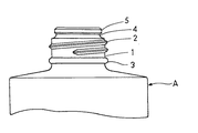
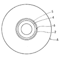
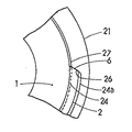
図1,2に示すように、容器Aの容器口部1外周には、ネジ2と保持突条3が設けられており、口部上端は、縮径口部4とされその外周に嵌合突条5が設けられている。
前記ネジ2の上部始端のネジ切り始め部分には、60度ないし90度近くの傾斜角をもった立上がり部6が形成されている。
【0011】
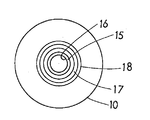
図3,4に示すように、中栓Bは、前記容器口部1に被嵌する嵌着筒10と上壁11、および容器口部1内周に嵌合される嵌合筒12とを具えており、嵌着筒10の内周は、嵌合突条5に係合する嵌合面13となっており、その下端には嵌合突条14が設けられている。
上壁11の上面中央には、注出筒15が立設され、その内周は注出孔16となっている。
注出筒15の外側には、係止リング17が立設されており、その上端外周には、外方に突出する膨出部18が設けられている。
【0012】
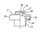
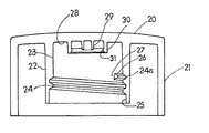
図5,6に示すように、キャップCは、頂壁20と側筒壁21とを備えており、側筒壁21の内側には、嵌着筒22が設けられている。
嵌着筒22の内周23には、その中間部より下方に容器口部1のネジ2に螺合するネジ24が刻設されており、内周23下端部はネジ溝24aと同径の拡径段部25となっている。
ネジ24の上終端部には、ネジ溝24a終端底面から起立し前記容器口部1のネジ2の立上がり部6と接合する傾斜面26が形成されており、該傾斜面26は、ストッパ部27となっている。
【0013】
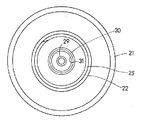
嵌着筒22に囲まれた頂壁内面28には、その中央部に前記注出筒15の内周に嵌着される密封リング29が垂設され、該密封リング29を囲んで、係止リング30が垂設されている。
係止リング30内周には、内方に突出する膨出部31が設けられている。
【0014】
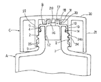
次に、上記構成による作用効果について、図7,8を参照して説明する。
中栓Bは、打栓によって容器Aの容器口部1上端に被嵌されるが、その際、中栓Bの嵌着筒10内周の嵌合面13が容器口部1の嵌合突条5に嵌合され、嵌合突条14は嵌合突条5の下面に係合し、嵌合突条5と嵌着筒10内周,嵌合筒12と容器口部1内周とは一定の締め代をもって嵌着される。
【0015】
キャップCは、螺合により容器口部1に締着されるが、締着にあたってキャップCを回していくと、締着時には、キャップCのストッパ部27の傾斜面26が容器口部1のネジ2の立上がり部6に衝接してキャップCが位置決めされ、その際、密封リング29が中栓Bの注出孔16を一定の締め代をもって密封する。
【0016】
キャップCの下降に際して、キャップCの係止リング30の膨出部31が、中栓Bに立設した係止リング17の膨出部18を乗り越えて下降し、キャップ締着時には、膨出部31は中栓Bの膨出部18の下側に係合する。
キャップが下降し、相互の膨出部18,31が接合すると、キャップの回動に抵抗感が生じ、膨出部31が膨出部18を乗り越えるときには、抵抗感は最大に高まる。
締着直前には、抵抗は弱まるので、使用者は抵抗感の変化によってキャップが完全に締着したか否かを感じとることができる。
【0017】
【発明の効果】
本発明は、上記のように構成されているから、次の効果を奏する。
キャップの位置決めを、容器口部に刻設したネジの上始端部の立上がり部と、キャップのネジの上終端部に形成した傾斜面の衝接により位置決めしているので、位置決めがネジの円周方向となり、ネジの軸線方向の位置決めよりも微細に位置決め位置を設定することができ、位置決め精度をあげることができるようになった。
また、ストッパ部は、それぞれのネジの始端、終端との間に形成されているだけであるので、ネジ自体は従来のものでよく、キャップの高さもとくに変えることなく、より低く設定することもできる。
【0018】
中栓とキャップに膨出部を設けた係止リングを設けているので、キャップ締着時に使用者にフィニッシュ感を与えることができ、不安感を解消することができる。
係止リングの成形も、その作用がフィニッシュ感を出すだけであるので、寸法精度を高くする必要はなく、膨出部は、アンダーカットとして成形できるので、係止リングの成形が容易にできる。
【図面の簡単な説明】
【図1】本発明の容器口部の縦断面図である。
【図2】容器の平面図である。
【図3】中栓の平面図である。
【図4】中栓の一部断面正面図である。
【図5】 キャップの一部断面正面図である。
【図6】キャップの底面図である。
【図7】容器,中栓,キャップの組立断面図である。
【図8】容器口部のネジ上始端部とストッパ部との関係を示す説明図である。
【図9】 従来の容器を示す組立断面図である。
【符号の説明】
A,A1 容器
B,B1 中栓
C,C1 キャップ
1,40 容器口部
2,42 ネジ
6 立上がり部
15,49 注出筒
16,50 注出孔
17,30 係止リング
18,31 膨出部
24,52 ネジ
24a ネジ溝
26 傾斜面
27 ストッパ部
29,55 密封リング[0001]
BACKGROUND OF THE INVENTION
The present invention relates to a content liquid dispensing container, particularly a liquid dispensing container fitted with a screw-type cap, and a content liquid provided with a cap that is positioned by a stopper disposed at the screw end when the cap is fastened. Regarding the dispensing container.
[0002]
[Prior art]
A liquid dispensing container that has been fitted with an inner stopper with a dispensing cylinder standing upright at the mouth of the container and covered with a cap has been well known in the past, and there are many proposals for positioning the cap. Has been made.
As an example, a container as shown in FIG. 9 has been proposed.
In the figure, A1 is a container, and a
An enlarged
[0003]
B1 is an inner plug, and includes an
A
[0004]
C1 is a cap, and the
On the lower surface of the
[0005]
[Problems to be solved by the invention]
In the container, the positioning of the cap C1 in the vertical direction at the time of fastening is performed by simply bringing the
[0006]
However, in the said container, the enlarged
In addition, when the cap is tightened, there is a problem that the finish feeling is not the same as that of the conventional cap, and there is a problem that the user remains uneasy because it is not known whether the cap is completely closed. .
[0007]
In consideration of the above-mentioned problems, the present invention aims to improve the positioning accuracy by setting the positioning direction of the cap to the circumferential direction and reduce the height of the cap so as to give a finish feeling similar to that of a conventional container. It is a technical problem and aims to provide a new content dispensing container.
[0008]
[Means for Solving the Problems]
In order to increase the positioning accuracy of the cap, which is one of the technical problems described above, the present invention includes a container provided with a screw on the outer periphery of the container mouth, a top end of the container mouth, and a dispensing cylinder on the upper surface. In a liquid dispensing container consisting of an inner stopper provided and a cap provided with a sealing ring that is screwed onto the outer periphery of the container mouth and closes the spout on the inner surface of the top wall, above the screw engraved on the outer periphery of the container mouth A rising portion having a predetermined inclination angle is formed at the start end portion, and an inclined surface is formed on the upper end portion of the screw engraved on the inner periphery of the cap fitting cylinder so as to stand up from the bottom surface of the screw groove and join to the rising portion. A stopper is used.
[0009]
Further, in order to give a feeling of finish, in the above-described liquid dispensing container, a locking ring provided with a bulging portion protruding outward is provided on the outer side of the dispensing tube of the inner stopper, and the inner surface of the top wall of the cap An arrangement is employed in which a locking ring is provided on the outside of the sealing ring, which is engaged with the bulging portion and provided with a bulging portion protruding inward.
[0010]
DETAILED DESCRIPTION OF THE INVENTION
Next, embodiments of the present invention will be described with reference to the drawings.
The present invention includes a container A formed of glass or synthetic resin, an inner stopper B formed of synthetic resin, and a cap C.
As shown in FIGS. 1 and 2, a
A rising
[0011]
As shown in FIGS. 3 and 4, the inner stopper B includes a
A
A
[0012]
As shown in FIGS. 5 and 6, the cap C includes a
A
The upper end portion of the
[0013]
A
A bulging
[0014]
Next, the effect by the said structure is demonstrated with reference to FIG.
The inner plug B is fitted to the upper end of the
[0015]
The cap C is fastened to the
[0016]
When the cap C is lowered, the bulging
When the cap is lowered and the bulging
Immediately before the fastening, the resistance is weakened, so that the user can feel whether the cap is completely fastened by the change in resistance.
[0017]
【The invention's effect】
Since this invention is comprised as mentioned above, there exists the following effect.
The cap is positioned by the contact between the rising part of the top start end of the screw engraved in the container mouth and the inclined surface formed at the top end of the cap screw. The positioning position can be set finer than the positioning in the axial direction of the screw, and the positioning accuracy can be improved.
Moreover, since the stopper part is only formed between the start end and the end of each screw, the screw itself may be a conventional one, and the cap height can be set lower without any particular change. it can.
[0018]
Since the locking ring provided with the bulging portion on the inner plug and the cap is provided, a finish feeling can be given to the user when the cap is fastened, and anxiety can be eliminated.
Since the locking ring is formed only by the action, it is not necessary to increase the dimensional accuracy, and the bulging portion can be formed as an undercut, so that the locking ring can be easily formed.
[Brief description of the drawings]
FIG. 1 is a longitudinal sectional view of a container mouth portion of the present invention.
FIG. 2 is a plan view of the container.
FIG. 3 is a plan view of the inner plug.
FIG. 4 is a partial sectional front view of the inner plug.
FIG. 5 is a partial cross-sectional front view of a cap.
FIG. 6 is a bottom view of the cap.
FIG. 7 is an assembled cross-sectional view of a container, an inner stopper, and a cap.
FIG. 8 is an explanatory view showing a relationship between a screw start end portion of a container mouth portion and a stopper portion.
FIG. 9 is an assembled cross-sectional view showing a conventional container.
[Explanation of symbols]
A, A1 Container B, B1 Inner plug C,
Claims (1)
容器口部外周に刻設したネジの上始端部に、所定の傾斜角を有する立上がり部を形成し、キャップの嵌着筒内周に刻設したネジの上終端部に、前記立上がり部と接合する傾斜面を形成しストッパ部とし、
中栓の注出筒外側に、外方に突出する膨出部を設けた係止リングを立設し、
キャップの頂壁内面の密封リングの外側に、前記膨出部に係合し、内方に突出する膨出部を設けた係止リングを垂設したことを特徴とする内容液注出容器。 A container engraved with a screw on the outer periphery of the container mouth, an inner stopper fitted on the upper end of the container mouth, and provided with an extraction tube on the upper surface, and screwed onto the outer periphery of the container mouth, and a spout on the inner surface of the top wall In a liquid dispensing container consisting of a cap with a sealing ring to close,
A rising portion having a predetermined inclination angle is formed at the upper start end of the screw engraved on the outer periphery of the container mouth, and the upper end of the screw engraved on the inner periphery of the fitting tube of the cap is joined to the rising end. Forming an inclined surface to be used as a stopper,
A locking ring with a bulging part protruding outward is set up on the outer side of the inner tube of the inner plug,
A content liquid dispensing container, wherein a locking ring is provided on the outer side of the sealing ring on the inner surface of the top wall of the cap so as to be engaged with the bulging portion and provided with a bulging portion protruding inward.
Priority Applications (1)
| Application Number | Priority Date | Filing Date | Title |
|---|---|---|---|
| JP31272396A JP3649826B2 (en) | 1996-11-08 | 1996-11-08 | Contents liquid dispensing container |
Applications Claiming Priority (1)
| Application Number | Priority Date | Filing Date | Title |
|---|---|---|---|
| JP31272396A JP3649826B2 (en) | 1996-11-08 | 1996-11-08 | Contents liquid dispensing container |
Publications (2)
| Publication Number | Publication Date |
|---|---|
| JPH10139052A JPH10139052A (en) | 1998-05-26 |
| JP3649826B2 true JP3649826B2 (en) | 2005-05-18 |
Family
ID=18032650
Family Applications (1)
| Application Number | Title | Priority Date | Filing Date |
|---|---|---|---|
| JP31272396A Expired - Lifetime JP3649826B2 (en) | 1996-11-08 | 1996-11-08 | Contents liquid dispensing container |
Country Status (1)
| Country | Link |
|---|---|
| JP (1) | JP3649826B2 (en) |
-
1996
- 1996-11-08 JP JP31272396A patent/JP3649826B2/en not_active Expired - Lifetime
Also Published As
| Publication number | Publication date |
|---|---|
| JPH10139052A (en) | 1998-05-26 |
Similar Documents
| Publication | Publication Date | Title |
|---|---|---|
| KR960013293B1 (en) | Linerless closure for carbonated beverage container | |
| US4090630A (en) | Container closure | |
| JP3789611B2 (en) | Extrusion container | |
| JP3649826B2 (en) | Contents liquid dispensing container | |
| BRPI0910624B1 (en) | COMPACT INVIOLABLE LOCK COVER | |
| US6056161A (en) | Push-pull dispenser | |
| JPH0714209Y2 (en) | Mouth with cap | |
| JP2568203Y2 (en) | Liquid container stopper | |
| JP2589341Y2 (en) | Synthetic resin cap | |
| JPH0287760U (en) | ||
| JPH0424803Y2 (en) | ||
| JP3837590B2 (en) | Dispensing container | |
| JP2535506Y2 (en) | Two-liquid storage container | |
| JP2599796Y2 (en) | Container cap | |
| JP3221267B2 (en) | Sealing cap | |
| JPS6242906Y2 (en) | ||
| JPH034352Y2 (en) | ||
| JPH0327973Y2 (en) | ||
| JPS5841162Y2 (en) | Cap loosening mechanism | |
| JPS5911892Y2 (en) | Structure related to screw cap and container opening | |
| JPH0136772Y2 (en) | ||
| JPS5815313Y2 (en) | Container with cap for liquid dispensing | |
| JP2504907Y2 (en) | cap | |
| JP2552671Y2 (en) | Two-part mixing container | |
| JP2575208Y2 (en) | Two-part mixing container |
Legal Events
| Date | Code | Title | Description |
|---|---|---|---|
| A977 | Report on retrieval |
Free format text: JAPANESE INTERMEDIATE CODE: A971007 Effective date: 20040910 |
|
| A131 | Notification of reasons for refusal |
Free format text: JAPANESE INTERMEDIATE CODE: A131 Effective date: 20040921 |
|
| A521 | Written amendment |
Free format text: JAPANESE INTERMEDIATE CODE: A523 Effective date: 20041122 |
|
| TRDD | Decision of grant or rejection written | ||
| A01 | Written decision to grant a patent or to grant a registration (utility model) |
Free format text: JAPANESE INTERMEDIATE CODE: A01 Effective date: 20050215 |
|
| A61 | First payment of annual fees (during grant procedure) |
Free format text: JAPANESE INTERMEDIATE CODE: A61 Effective date: 20050216 |
|
| R150 | Certificate of patent or registration of utility model |
Free format text: JAPANESE INTERMEDIATE CODE: R150 |
|
| FPAY | Renewal fee payment (event date is renewal date of database) |
Free format text: PAYMENT UNTIL: 20080225 Year of fee payment: 3 |
|
| FPAY | Renewal fee payment (event date is renewal date of database) |
Free format text: PAYMENT UNTIL: 20090225 Year of fee payment: 4 |
|
| FPAY | Renewal fee payment (event date is renewal date of database) |
Free format text: PAYMENT UNTIL: 20090225 Year of fee payment: 4 |
|
| FPAY | Renewal fee payment (event date is renewal date of database) |
Free format text: PAYMENT UNTIL: 20100225 Year of fee payment: 5 |
|
| FPAY | Renewal fee payment (event date is renewal date of database) |
Free format text: PAYMENT UNTIL: 20100225 Year of fee payment: 5 |
|
| FPAY | Renewal fee payment (event date is renewal date of database) |
Free format text: PAYMENT UNTIL: 20110225 Year of fee payment: 6 |
|
| FPAY | Renewal fee payment (event date is renewal date of database) |
Free format text: PAYMENT UNTIL: 20120225 Year of fee payment: 7 |
|
| FPAY | Renewal fee payment (event date is renewal date of database) |
Free format text: PAYMENT UNTIL: 20130225 Year of fee payment: 8 |
|
| FPAY | Renewal fee payment (event date is renewal date of database) |
Free format text: PAYMENT UNTIL: 20130225 Year of fee payment: 8 |
|
| FPAY | Renewal fee payment (event date is renewal date of database) |
Free format text: PAYMENT UNTIL: 20140225 Year of fee payment: 9 |
|
| EXPY | Cancellation because of completion of term |