JP3649817B2 - Scroll type fluid machinery - Google Patents
Scroll type fluid machinery Download PDFInfo
- Publication number
- JP3649817B2 JP3649817B2 JP22591296A JP22591296A JP3649817B2 JP 3649817 B2 JP3649817 B2 JP 3649817B2 JP 22591296 A JP22591296 A JP 22591296A JP 22591296 A JP22591296 A JP 22591296A JP 3649817 B2 JP3649817 B2 JP 3649817B2
- Authority
- JP
- Japan
- Prior art keywords
- scroll
- orbiting scroll
- fixed
- balance weight
- ball bearing
- Prior art date
- Legal status (The legal status is an assumption and is not a legal conclusion. Google has not performed a legal analysis and makes no representation as to the accuracy of the status listed.)
- Expired - Fee Related
Links
- 239000012530 fluid Substances 0.000 title claims description 8
- 230000006835 compression Effects 0.000 claims description 16
- 238000007906 compression Methods 0.000 claims description 16
- 230000008878 coupling Effects 0.000 claims description 7
- 238000010168 coupling process Methods 0.000 claims description 7
- 238000005859 coupling reaction Methods 0.000 claims description 7
- 230000000694 effects Effects 0.000 description 2
- 230000002093 peripheral effect Effects 0.000 description 2
- 238000009434 installation Methods 0.000 description 1
- 239000000314 lubricant Substances 0.000 description 1
- 239000002184 metal Substances 0.000 description 1
- 230000001105 regulatory effect Effects 0.000 description 1
- 230000003014 reinforcing effect Effects 0.000 description 1
- 230000000452 restraining effect Effects 0.000 description 1
- 125000006850 spacer group Chemical group 0.000 description 1
- 229920003002 synthetic resin Polymers 0.000 description 1
- 239000000057 synthetic resin Substances 0.000 description 1
Images
Classifications
-
- F—MECHANICAL ENGINEERING; LIGHTING; HEATING; WEAPONS; BLASTING
- F04—POSITIVE - DISPLACEMENT MACHINES FOR LIQUIDS; PUMPS FOR LIQUIDS OR ELASTIC FLUIDS
- F04C—ROTARY-PISTON, OR OSCILLATING-PISTON, POSITIVE-DISPLACEMENT MACHINES FOR LIQUIDS; ROTARY-PISTON, OR OSCILLATING-PISTON, POSITIVE-DISPLACEMENT PUMPS
- F04C29/00—Component parts, details or accessories of pumps or pumping installations, not provided for in groups F04C18/00 - F04C28/00
- F04C29/0021—Systems for the equilibration of forces acting on the pump
-
- F—MECHANICAL ENGINEERING; LIGHTING; HEATING; WEAPONS; BLASTING
- F04—POSITIVE - DISPLACEMENT MACHINES FOR LIQUIDS; PUMPS FOR LIQUIDS OR ELASTIC FLUIDS
- F04C—ROTARY-PISTON, OR OSCILLATING-PISTON, POSITIVE-DISPLACEMENT MACHINES FOR LIQUIDS; ROTARY-PISTON, OR OSCILLATING-PISTON, POSITIVE-DISPLACEMENT PUMPS
- F04C2240/00—Components
- F04C2240/80—Other components
- F04C2240/807—Balance weight, counterweight
Landscapes
- Engineering & Computer Science (AREA)
- Mechanical Engineering (AREA)
- General Engineering & Computer Science (AREA)
- Rotary Pumps (AREA)
Description
【0001】
【発明の属する技術分野】
この発明は、電動機により揺動スクロールを公転させ、固定スクロールとの間に形成された圧縮空間を外方から内方に向けて縮小させることにより、気体を圧縮して吐出する圧縮機や、揺動スクロールを逆回りに公転させ、気体を膨張させて吐出する膨張機等のスクロール型流体機械に関するものである。
【0002】
【従来の技術】
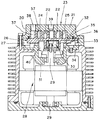
スクロール型流体機械として、従来、図4に示す圧縮機が知られている。その圧縮機は、環状壁20に囲まれ鏡板21に立設された螺旋状のフラップ22を有する固定スクロール23と、鏡板24に立設された螺旋状のフラップ25を有する揺動スクロール26と、揺動スクロール26を固定スクロール23に対して自転しないように円軌道上を公転させるオルダム継手27と、電動機28とより構成されており、電動機28の回転軸29には偏心ブッシュ30が一体化され、偏心ブッシュ30が揺動スクロール26のボス部31内にニードルベアリング32を介して挿入され、揺動スクロール26の鏡板24の背面に一体形成された補強リブ33を受けるフレーム34には、潤滑剤35を塗布した環状の金属製又は合成樹脂製スラストキャップ36が嵌合されている。また、フラップ22とフラップ25が互いに向かいを合わせにかみ合わされて内部に複数の圧縮空間37が形成されており、鏡板21の外周部付近及び中央部には、それぞれ圧縮空間37に連通する吸引孔38と吐出孔39が設けられている。
【0003】
このような圧縮機は、電動機28が駆動して偏心ブッシュ30が回転すると、揺動スクロール26がオルダム継手27に規制されて円軌道上を公転する。その結果、両スクロール23、26間に形成されている圧縮空間37が外方から内方に向けて順次に縮小させ、吸引孔38から流入した気体が圧縮され、吐出孔39から吐き出される。
【0004】
【発明が解決しようとする課題】
上記のスクロール型圧縮機は、バランスウエイト40の他に、揺動スクロール26を公転させるための偏心ブッシュ30が必要である。また、揺動スクロール26の公転時の遠心力及び、圧縮空間37を構成する揺動スクロール26のフラップ25を中心より外側に向けて押圧する空気圧を支えるニードルベアリング32、揺動スクロール26の鏡板24を軸方向下方に押圧する空気圧を打ち消すために電動機28側よりかける中間圧及びスラスト力を受けるスラストキャップ36が必要であり、複雑である。更に、偏心ブッシュ30により揺動スクロール26に半強制的な偏心回転を強いるので、固定スクロール23と強い当りが生じ、運動中に衝撃を生じることがある。
【0005】
この発明は、より簡単な構造のスクロール型流体機械を提供することを目的としている。
【0006】
【課題を解決するための手段】
本発明の請求項1のスクロール型流体機械は、固定スクロール1と揺動スクロール2とをそれぞれに立設した螺旋状フラップ1c、2bを互いに向かいを合わせにかみ合わせて複数の圧縮空間12を形成し、揺動スクロール2を円軌道上を公転させることにより圧縮空間12を外方から内方に向けて又はその逆向きに順次縮小させ、圧縮空間12に通じる一方の孔1dと他方の孔1eとの間で気体を吸引し、圧縮又は膨張させて吐出するものであって、バランスウエイト5上面と揺動スクロール2背面との間にスラストボールベアリング6を設けたものである。
【0007】
また、スラストボールベアリング6の設置位置が、バランスウエイト5側では回転中
心より偏心した位置であり、揺動スクロール2側では中央位置である。
【0008】
更に、請求項2の発明では、揺動スクロール2の自転を規制するオルダム継手3を設けている。
【0009】
【発明の実施の形態】
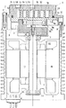
図1及び図2を参照し、この発明のスクロール型流体機械の圧縮機としての実施形態について説明する。
【0010】
この圧縮機は、固定スクロール1と、固定スクロール1に対して円軌道上を公転する揺動スクロール2と、揺動スクロール2を自転しないように規制するオルダム継手3と、揺動スクロール2を公転させるための電動機4と、電動機4の回転軸4aに固定されたバランスウエイト5と、揺動スクロール2とバランスウエイト5との間に設けられたスラストボールベアリング6とより構成されている。
【0011】
モーターケース7にはオルダム継手33やバランスウエイト5等が収容されるケーシング8が固定ボルト9によって固定されている。固定スクロール1はスペーサー10を介して固定ボルト11によりケーシング8に固定されている。
【0012】
固定スクロール1の環状壁1bに囲まれ鏡板1aには、螺旋状のフラップ1cが立設されている。また、鏡板1aの外周部付近及び中央部には、後述する圧縮空間12にそれぞれ連通する吸引孔1dと吐出孔1eが設けられている。
【0013】
揺動スクロール2の鏡板2aの上面には、螺旋状のフラップ2bが立設されている。
【0014】
固定スクロール1と揺動スクロール2とは、フラップ1cとフラップ2bを互いに向かいを合わせにかみ合わせて内部に複数の圧縮空間12を形成している。13は、圧縮空間12より圧縮空気が漏れないようにシールする弾性体よりなる環状のシールである。
【0015】
オルダム継手3は、揺動スクロール2を固定スクロール1に対して自転しないように円軌道上を公転させるものであり、そのキーは揺動スクロール2の鏡板2a背面に形成されたキー溝と係合するようになっている。
【0016】
電動機4は、モーターケース7内に固定された固定子4bと、この固定子4bの内側に配された回転子4cとよりなっている。
【0017】
モーターカバー7及びケーシング8には、それぞれ回転軸4aを軸支するボールベアリング14、15が設けられている。
【0018】
バランスウエイト5の上面には、回転軸4aの中心から偏心した位置にあるリング状の壁面5aが形成されている。このバランスウエイト5は、揺動スクロール2の偏心運動(公転運動)とのバランスをとるためのものであり、電動機4の回転軸4aの上端に固定ボルト16によって固定されている。
【0019】
スラストボールベアリング6の上輪6aは、揺動スクロール2の鏡板2aの背面における中央位置に固定され、下輪6bは、バランスウエイト5の上面におけるリング状壁面5a内に固定され、それらの溝に複数のボール6cが挟まれて収容されている。従って、スラストボールベアリング6は、バランスウエイト5においては、回転軸4aの中心から偏心した位置に存在する。
【0020】
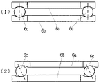
このスラストボールベアリング6においては、揺動スクロール2の公転運動によって上輪6aに遠心力が作用し、図2(2)に示すように、下輪6bに対してずれると、上輪6aと下輪6bの上下の間隔が大きくなり、揺動スクロール2は自然に上方に押し上げられ、圧縮空間12の気密保持に作用する。従って、従来のもののような、揺動スクロールを固定スクロール側に押圧する中間圧の付与が不要となる。
【0021】
電動機3の回転力は回転軸4aよりバランスウエイト5とスラストボールベアリング6を介して公転運動として揺動スクロール2に伝えられる。即ち、上輪6aと下輪6bの間隔は、ボール6cが外れる程には大きくならないようにしてあり、そのボール6cの拘束力によって揺動スクロール2の公転が決められた円軌道をとるようになる。
【0022】
このような圧縮機は、電動機3が駆動してバランスウエイト5が回転すると、スラストボールベアリング6の下輪6bがバランスウエイト5の偏心位置に固定されているので、揺動スクロール2は、スラストボールベアリング6のボール6c及び上輪6aに追随して偏心した自転を行おうとするが、オルダム継手3に自転を規制され、円軌道上を公転する。その結果、両スクロール1、2間に形成されている圧縮空間12が外方から内方に向けて次第に縮小させ、吸引孔1dから流入した気体が圧縮され、吐出孔1eから吐き出される。
【0023】
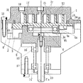
次に、図3を参照し、スクロールユニットとしての実施形態について説明する。これも、電動機を除いた部分は、働き含めて前実施形態と基本的に一致しているので、相違点のみ説明する。
【0024】
このスクロールユニットにおいては、電動機及びモーターケースは存在せず、固定スクロール1が固定されるケーシング8’の形状も異なっている。電動機の回転軸に対応するシャフト4’aを軸受けするボールベアリング14’、15’は、ケーシング8’に設けられており、ケーシング8’の下端には、固定ボルト17によってカバー18が被されている。19は、軸シールである。また、13’は、チップシールである。
【0025】
このスクロールユニットは、シャフト4’aが別体の駆動原に接続され、圧縮機として使用することができるが、シャフト4’aを逆に回転させて、揺動スクロール2を逆回りに公転させるようにすれば、気体を膨張させる膨張機としても使用することができる。膨張機としても使用できる点は、先の実施形態も同様である。
【0026】
【発明の効果】
この発明は、以上説明したように構成されているので、以下に記載するような効果を奏する。
【0027】
即ち、従来のものに必須であった偏心ブッシュ、ニードルベアリング及び揺動スクロールを固定スクロール側に押圧する中間圧の付与が不要となり、簡単な構造とすることができる。
【0028】
スラストボールベアリングは、従来のもののスラストキャップのような滑り軸受とは異なり、摩擦係数が低いので、スラスト力が加わり、負荷が大きくなっても滑らかな回転を保つことができ、高速回転にも対応することができる。従って、バランスウエイトは揺動スクロールを支えながらスムーズに回転することができる。その上、スラストボールベアリングのボールが軌道溝中に拘束されるので、揺動スクロールの規制範囲内での二次元運動が約束される。
【0029】
また、揺動スクロールの偏心回転が、その中央位置とバランスウエイトの回転中心より偏心した位置との間にあるスラストボールベアリングによってなされるので、固定スクロールとの間に強い当りが生じても、スラストボールベアリングの複数のボールによって適度に衝撃が緩和され、偏心ブッシュにより揺動スクロールを偏心回転させる従来のものに比べ、両スクロールの表面を損傷することはほとんどない。
【0030】
更に、揺動スクロールの運動を、バランスウエイトの回転中心より偏心した位置にあるスラストボールベアリングとオルダム継手によって規制するようにしたので、従来の偏心ブッシュとオルダム継手によるものに比べて、揺動スクロールの組み込みが極めて簡単である。
【図面の簡単な説明】
【図1】この発明に係る圧縮機の縦断面図である。
【図2】上記圧縮機に用いられるスラストボールベアリングの縦断面図であり、(1)は静止状態におけるもの、(2)は運動状態におけるものである。
【図3】この発明に係るスクロールユニットの縦断面図である。
【図4】従来のスクロール型圧縮機の縦断面図である。
【符号の説明】
1 固定スクロール
1c 螺旋状フラップ
1d 吸引孔(吐出孔)
1e 吐出孔(吸引孔)
2 揺動スクロール
2b 螺旋状フラップ
3 オルダム継手
4 電動機
5 バランスウエイト
6 スラストボールベアリング
12 圧縮空間[0001]
BACKGROUND OF THE INVENTION
The present invention relates to a compressor that compresses and discharges gas by rotating an orbiting scroll with an electric motor and reducing a compression space formed between the fixed scroll and the inside from the outside to the inside. The present invention relates to a scroll type fluid machine such as an expander that revolves a moving scroll in the reverse direction and expands and discharges gas.
[0002]
[Prior art]
Conventionally, a compressor shown in FIG. 4 is known as a scroll type fluid machine. The compressor includes a
[0003]
In such a compressor, when the
[0004]
[Problems to be solved by the invention]
The scroll compressor described above requires an
[0005]
An object of the present invention is to provide a scroll type fluid machine having a simpler structure.
[0006]
[Means for Solving the Problems]
A scroll type fluid machine according to a first aspect of the present invention forms a plurality of
[0007]
Further, the installation position of the thrust ball bearing 6 is a position eccentric from the center of rotation on the
[0008]
Furthermore, in the invention of
[0009]
DETAILED DESCRIPTION OF THE INVENTION
With reference to FIG.1 and FIG.2, embodiment as a compressor of the scroll type fluid machine of this invention is described.
[0010]
This compressor revolves the
[0011]
A casing 8 in which the Oldham coupling 33, the
[0012]
A spiral flap 1c is erected on the end plate 1a surrounded by the annular wall 1b of the
[0013]
On the upper surface of the
[0014]
The
[0015]
The Oldham
[0016]
The
[0017]
The motor cover 7 and the casing 8 are provided with
[0018]
On the upper surface of the
[0019]
The upper ring 6a of the thrust ball bearing 6 is fixed at the center position on the back surface of the
[0020]
In this thrust ball bearing 6, centrifugal force acts on the upper wheel 6a by the revolving motion of the orbiting
[0021]
The rotational force of the
[0022]
In such a compressor, when the
[0023]
Next, an embodiment as a scroll unit will be described with reference to FIG. In this case as well, the portion excluding the electric motor is basically the same as that of the previous embodiment, including the function, so only the differences will be described.
[0024]
In this scroll unit, there is no electric motor and motor case, and the shape of the casing 8 ′ to which the fixed
[0025]
In this scroll unit, the
[0026]
【The invention's effect】
Since the present invention is configured as described above, the following effects can be obtained.
[0027]
That is, it is not necessary to apply an intermediate pressure that presses the eccentric bush, the needle bearing, and the orbiting scroll toward the fixed scroll, which is essential for the conventional one, and the structure can be simplified.
[0028]
Thrust ball bearings have a low coefficient of friction unlike conventional thrust bearings like thrust caps, so thrust force is applied and smooth rotation can be maintained even when the load increases, and high speed rotation is also supported. can do. Accordingly, the balance weight can rotate smoothly while supporting the swing scroll. In addition, since the ball of the thrust ball bearing is restrained in the raceway groove, a two-dimensional motion within the restricted range of the orbiting scroll is promised.
[0029]
In addition, since the eccentric rotation of the orbiting scroll is performed by the thrust ball bearing between the center position and the position eccentric from the rotation center of the balance weight, even if a strong contact with the fixed scroll occurs, The impact is moderated moderately by the plurality of balls of the ball bearing, and the surface of both scrolls is hardly damaged compared to the conventional one in which the orbiting scroll is eccentrically rotated by the eccentric bush.
[0030]
Furthermore, since the motion of the orbiting scroll is regulated by the thrust ball bearing and Oldham joint that are eccentric from the center of rotation of the balance weight, the orbiting scroll is compared with the conventional eccentric bush and Oldham joint. Is extremely easy to incorporate.
[Brief description of the drawings]
FIG. 1 is a longitudinal sectional view of a compressor according to the present invention.
FIG. 2 is a longitudinal sectional view of a thrust ball bearing used in the compressor, wherein (1) is in a stationary state and (2) is in a moving state.
FIG. 3 is a longitudinal sectional view of a scroll unit according to the present invention.
FIG. 4 is a longitudinal sectional view of a conventional scroll compressor.
[Explanation of symbols]
1 fixed scroll 1c spiral flap 1d suction hole (discharge hole)
1e Discharge hole (suction hole)
2 oscillating scroll
Claims (2)
電動機の回転軸に固定されたバランスウエイトと、このバランスウエイト上面の回転中心より偏心した位置に設けられたスラストボールベアリングとを備え、このスラストボールベアリングを揺動スクロール背面の中央位置で固定したことを特徴とするスクロール型流体機械。A plurality of compression spaces are formed by meshing helical flaps, each of which has a fixed scroll and an orbiting scroll, and facing each other, and the orbiting scroll is revolved on a circular orbit to make the compression space from the outside. It is reduced in order toward the inward direction or in the opposite direction, the gas is sucked between one hole communicating with the compression space and the other hole, and compressed or expanded and discharged.
A balance weight fixed to the rotating shaft of the electric motor and a thrust ball bearing provided at a position eccentric from the center of rotation of the upper surface of the balance weight. The thrust ball bearing is fixed at the center position on the back of the orbiting scroll. A scroll type fluid machine characterized by
Priority Applications (1)
| Application Number | Priority Date | Filing Date | Title |
|---|---|---|---|
| JP22591296A JP3649817B2 (en) | 1996-08-08 | 1996-08-08 | Scroll type fluid machinery |
Applications Claiming Priority (1)
| Application Number | Priority Date | Filing Date | Title |
|---|---|---|---|
| JP22591296A JP3649817B2 (en) | 1996-08-08 | 1996-08-08 | Scroll type fluid machinery |
Publications (2)
| Publication Number | Publication Date |
|---|---|
| JPH1054379A JPH1054379A (en) | 1998-02-24 |
| JP3649817B2 true JP3649817B2 (en) | 2005-05-18 |
Family
ID=16836840
Family Applications (1)
| Application Number | Title | Priority Date | Filing Date |
|---|---|---|---|
| JP22591296A Expired - Fee Related JP3649817B2 (en) | 1996-08-08 | 1996-08-08 | Scroll type fluid machinery |
Country Status (1)
| Country | Link |
|---|---|
| JP (1) | JP3649817B2 (en) |
Families Citing this family (2)
| Publication number | Priority date | Publication date | Assignee | Title |
|---|---|---|---|---|
| JP2005030312A (en) | 2003-07-14 | 2005-02-03 | Toyota Industries Corp | Expansion machine which is also used for compressor |
| US9695823B2 (en) | 2013-10-31 | 2017-07-04 | Emerson Climate Technologies, Inc. | Compressor with unloader counterweight assembly |
-
1996
- 1996-08-08 JP JP22591296A patent/JP3649817B2/en not_active Expired - Fee Related
Also Published As
| Publication number | Publication date |
|---|---|
| JPH1054379A (en) | 1998-02-24 |
Similar Documents
| Publication | Publication Date | Title |
|---|---|---|
| JPH0826761B2 (en) | Scroll fluid machinery | |
| JPH04365902A (en) | Scroll type fluid machine | |
| JPS62142882A (en) | Scroll compressor | |
| US8206138B2 (en) | Scroll fluid machine with ball coupling rotation prevention mechanism | |
| JP4689050B2 (en) | Scroll machine | |
| JPH025787A (en) | Scroll compressor | |
| JPH03138472A (en) | scroll type fluid machine | |
| JP2000220582A (en) | Scroll fluid machine | |
| JP3649817B2 (en) | Scroll type fluid machinery | |
| JP3545826B2 (en) | Scroll compressor | |
| JP3124437B2 (en) | Scroll compressor | |
| JPH07208351A (en) | Scroll compressor | |
| JP2009127563A (en) | Scroll type compressor | |
| JPH04175486A (en) | Scroll type fluid machine | |
| JP2003201978A (en) | Scroll type fluid machine | |
| JPH02149783A (en) | Scroll type fluid machine | |
| JP2679480B2 (en) | Scroll compressor | |
| JPH0586801A (en) | Scroll-type fluid machine | |
| JP3061007B2 (en) | Scroll type fluid machine | |
| JP4676091B2 (en) | Scroll type fluid machine | |
| JPS6343422Y2 (en) | ||
| JPH07189930A (en) | Scroll type fluid machinery | |
| JP2925654B2 (en) | Scroll compressor | |
| JP2004169608A (en) | Scroll type air supply device | |
| JPS6325344Y2 (en) |
Legal Events
| Date | Code | Title | Description |
|---|---|---|---|
| RD02 | Notification of acceptance of power of attorney |
Free format text: JAPANESE INTERMEDIATE CODE: A7422 Effective date: 20040623 |
|
| A977 | Report on retrieval |
Free format text: JAPANESE INTERMEDIATE CODE: A971007 Effective date: 20041122 |
|
| A131 | Notification of reasons for refusal |
Free format text: JAPANESE INTERMEDIATE CODE: A131 Effective date: 20041130 |
|
| A521 | Written amendment |
Free format text: JAPANESE INTERMEDIATE CODE: A523 Effective date: 20041224 |
|
| TRDD | Decision of grant or rejection written | ||
| A01 | Written decision to grant a patent or to grant a registration (utility model) |
Free format text: JAPANESE INTERMEDIATE CODE: A01 Effective date: 20050201 |
|
| A61 | First payment of annual fees (during grant procedure) |
Free format text: JAPANESE INTERMEDIATE CODE: A61 Effective date: 20050216 |
|
| FPAY | Renewal fee payment (event date is renewal date of database) |
Free format text: PAYMENT UNTIL: 20090225 Year of fee payment: 4 |
|
| FPAY | Renewal fee payment (event date is renewal date of database) |
Free format text: PAYMENT UNTIL: 20090225 Year of fee payment: 4 |
|
| FPAY | Renewal fee payment (event date is renewal date of database) |
Free format text: PAYMENT UNTIL: 20100225 Year of fee payment: 5 |
|
| LAPS | Cancellation because of no payment of annual fees |