JP3645663B2 - Electrical equipment - Google Patents
Electrical equipment Download PDFInfo
- Publication number
- JP3645663B2 JP3645663B2 JP20709796A JP20709796A JP3645663B2 JP 3645663 B2 JP3645663 B2 JP 3645663B2 JP 20709796 A JP20709796 A JP 20709796A JP 20709796 A JP20709796 A JP 20709796A JP 3645663 B2 JP3645663 B2 JP 3645663B2
- Authority
- JP
- Japan
- Prior art keywords
- rotor
- rims
- disk
- pair
- phase
- Prior art date
- Legal status (The legal status is an assumption and is not a legal conclusion. Google has not performed a legal analysis and makes no representation as to the accuracy of the status listed.)
- Expired - Fee Related
Links
Images


Classifications
-
- H—ELECTRICITY
- H02—GENERATION; CONVERSION OR DISTRIBUTION OF ELECTRIC POWER
- H02K—DYNAMO-ELECTRIC MACHINES
- H02K37/00—Motors with rotor rotating step by step and without interrupter or commutator driven by the rotor, e.g. stepping motors
- H02K37/10—Motors with rotor rotating step by step and without interrupter or commutator driven by the rotor, e.g. stepping motors of permanent magnet type
- H02K37/12—Motors with rotor rotating step by step and without interrupter or commutator driven by the rotor, e.g. stepping motors of permanent magnet type with stationary armatures and rotating magnets
-
- H—ELECTRICITY
- H02—GENERATION; CONVERSION OR DISTRIBUTION OF ELECTRIC POWER
- H02K—DYNAMO-ELECTRIC MACHINES
- H02K21/00—Synchronous motors having permanent magnets; Synchronous generators having permanent magnets
- H02K21/12—Synchronous motors having permanent magnets; Synchronous generators having permanent magnets with stationary armatures and rotating magnets
- H02K21/125—Synchronous motors having permanent magnets; Synchronous generators having permanent magnets with stationary armatures and rotating magnets having an annular armature coil
-
- H—ELECTRICITY
- H02—GENERATION; CONVERSION OR DISTRIBUTION OF ELECTRIC POWER
- H02K—DYNAMO-ELECTRIC MACHINES
- H02K2201/00—Specific aspects not provided for in the other groups of this subclass relating to the magnetic circuits
- H02K2201/12—Transversal flux machines
Landscapes
- Engineering & Computer Science (AREA)
- Power Engineering (AREA)
- Permanent Magnet Type Synchronous Machine (AREA)
- Permanent Field Magnets Of Synchronous Machinery (AREA)
- Dynamo-Electric Clutches, Dynamo-Electric Brakes (AREA)
Description
【0001】
【発明の属する技術分野】
本発明は、電気機器に関し、特に横磁束原理によって作動する同期機器に関する。
【0002】
【従来の技術】
横磁束原理によって作動する同期機器は、回転子と同軸の円形コイルの形態である電機子巻線とからなる。電機子巻線は、一連の固定子コアによって、回転子のリムに取り付けられた永久磁石によって発生した磁束を連結する。この構成の利点は、電機子巻線に必要なスペースを侵食することなしに、より多くの磁束を支持することができるように固定子コアの部分を増大することができることにある。
【0003】
横磁束機器のこれまでの構成において、回転子のリムは、絶縁スペーサによって分離された並列の2列の永久磁石を支持している。2つの円形の固定子コイルが使用され、固定子コアは、回転子の内側及び外側の双方に組み込まれ、その結果、回転子の内外面の双方で有効なトルクが提供される。
【0004】
この構成に関する機器の問題は、固定子コイルを固定子のコアに包囲されるように組み立てることが困難なことである。回転子リムは長く、剛性が欠如しており、回転子は半径方向の衝撃に対して剛性が小さいのでたわみ易い。磁束が交番するとき固定子コアへの半径方向の力は、固定子ケーシングの半径方向の動きを生じる。このゼロオーダの固定子ケースの振動は、ケーシングを厚くすることなしに解消するのは困難である。
【0005】
横磁束モータの構成は、最近これらの問題を解決するために改善された。
【0006】
改良された構成は一連の固定子コアがまたぐ一列の永久磁石からなるリムを有する。固定子コアの両端部は回転子のリムをまたぐように半径方向に変位している。
【0007】
これらの改良された横磁束モータに関する問題は、隣接するモータ位相に属する固定子コアが著しい電磁結合を受け、これが機器の性能を低下させることである。
【0008】
本発明は、モータの周りの電磁結合の量を低減する横磁束モータを提供することを目的とする。
【課題を解決するための手段】
本発明による電気機器は、軸線の周りで回転可能な回転子軸と該回転子軸から伸び前記回転軸と共に回転可能な少なくとも1つのディスクとを含む回転子を有し、前記回転子ディスクは、前記回転子ディスクに固定された少なくとも一対の、円周に延在する回転子リムを有し、各対の前記リムは前記回転子ディスクの両側の同じ半径位置で固定されており、前記各回転子リムは、交互に配置された一列の磁石及び磁極片から成り、前記回転子リムに隣接しそれに面して配置されている固定子コアを有する固定子組立体と向き合っており、電機子巻線が前記固定子を作動可能に励磁するために前記固定子コア内に配置されている横磁束型電気機器において、作動時に前記回転子ディスクの特定の半径位置における一対の前記回転子リムのための前記電機子巻線は、互いに逆位相の電流によって励磁され、各対の回転子リムにおける回転子磁石若しくは回転子磁石及び固定子コアは、長い通路の磁束が相殺されるように配置されていることを特徴とする。
【0009】
本発明の1つの実施例において、長い通路の磁束は、各リムの磁石が互いに反対の極性を有し、固定子コアが互いに反対の形状を有するように各対のリムを配置することによって相殺される。
【0010】
本発明の第2の実施例において、長い通路の磁束は各リムの磁石を反対方向に傾斜するように配置することによって相殺される。
【0011】
複数のディスクを有する本発明の電気機器は、1つのディスクの1対のリムの位相が、トルクリップルを低減するために、他のディスクのリムの対の位相に対してずれている。
【0012】
本発明の1つの実施例において、トルクリップルを低減するために3つのディスクを有する電気機器は、各リムの対の位相が他のディスクのリムの対の位相に対して120°ずれている。
【0013】
複数対のリムがディスクの異なる半径位置で各ディスクに設けられる。トルクリップルを低減するために好ましくは、1つのディスクのリムの対の位相は、同じディスクの他の対のリムの位相に対してずれている。
【0014】
本発明の他の実施例において、2対のリムがディスクの異なる半径位置で各ディスクに設けられ、トルクリップルを低減するために、リムの半径方向外側の対の位相は、半径方向内側の対の位相に対して90°ずれている。
【0015】
【発明の実施の形態】
以下、本発明の実施例を図面を参照して詳細に説明する。
【0016】
図1を参照すると、参照符号10で指示された横磁束モータは、回転子及び固定子組立体を有する。
【0017】
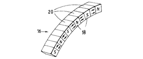
回転子組立体は、中空軸12のフランジ13に結合された4つの回転ディスク14を有する。各ディスク14は、4つのモータ位相のための回転子作動部品を支持する4つの円周方向の回転子リム16を有する。回転子リム16は、交互に配列された一列の積層磁極片18及び永久磁石20から成る。
【0018】
適当な磁石材料は、サマリウムコバルト及びネオジミウム鉄ボロンのような高エネルギー希土磁石材料である。磁石はその中の渦電流を制限するために細分されている。
【0019】
磁石20は、図2に示すように円周方向に配向されており、その結果、2つの磁石20からの磁束は、1つの磁極片18に集中される。磁極片18は、ボルト(図示せず)によって圧縮されて保持される薄層から成る。
【0020】
各回転子リム16に対向しているのは、一連の固定子コア22である。コイル24が回転子のリム16の周りの固定子コア22の間に配置されている。コイル24及び固定子コア22は、固定子フレームに支持されている。固定子フレームは、フランジを介してハウジング28に固定された固定子ディスク26を有する。固定子コア22は、固定子ディスク26のスロットに配置される。固定子ディスク26は、アルミニウムから製造され熱を除去するために高熱伝導性を有する。冷却接続部29を通して、水のような冷却剤が冷却のために供給される。
【0021】
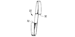
固定子コア22は、図3に示すようなC形状であり、必要な磁束の集中を与えるように、隣接する2つの磁石から磁束を受けることができるように配置される。固定子コア22または回転子リム16の磁石20は、各固定子コア22が2つの対向する(N及びS)薄層磁極片18の周りをまたぐように傾斜している。
【0022】
図4及び図5は、前述した構成を有する異なる形状の固定子コア22を示す。本発明の異なる実施例において、固定子コア22は図5に示すように非対称形である。
【0023】
作用において、交流電流は固定子フレーム28に取り付けられた端子ボックス36からコイル24を通過して回転磁界を生じる。回転子は磁石20が回転磁界に追従するときに回転する。各コイル24によって発生したトルクは、通常正弦波であり、磁極20及び32が互いに引き付けたときにゼロとなる。円滑で安定したトルクを得るために、複数の位相が必要である。複数の位相は、複数のディスクかまたはディスク毎の複数の位相によって提供される。位相は、正弦波のトルクリップルが相殺されるように補完的なトルクを与えるように配置される。
【0024】
トルクリップルの相殺は、対をなす位相が互いに補完的であることを意味する。これは位相の方向の変位を意味し、すなわち、電流及び電極または固定子コアがリムの対の間で変位することを意味する。トルクリップルを相殺するために位相は90°離れていなければならない。しかしながら、90°の電気的な位相間隔では、位相間でかなりの電磁結合があり、モータの性能が低下する。電磁結合の結果、渦電流が発生し、回転子ディスク12を通過して大きな電磁的な損失が生じる。
【0025】
もし、ディスク14の両側の位相が180度電気的に変位している(逆位相)のであれば電磁結合および渦電流を無くすことができる。
【0026】
また、隣接する回転子リム16の長い通路の磁束が等しく反対であるように配置することによって長い通路の磁束を相殺する必要がある。長い通路の磁束を相殺しなければ、回転子軸12及び固定子フレームとを通過する円形電流が生じる。
【0027】
固定子コア22の上方端部を通る磁束は図8の磁石2によって生成される短い通路の磁束と、磁石1によって生成される長い通路の磁束とから成る。磁束の集束は、双方の磁石1及び2が磁束を固定子コア22の上方端部に通すことができることに依存する。しかしながら、短い磁束通路は単一の固定子コア22を介して電機子巻線24を単に連結する局所的な磁束ループから成るが、長い磁束通路は、図9に示すように磁石1及び3を含む全部の奇数番号の磁石を連結する。長い磁束通路は、固定子コア22全部と奇数番号の磁石全部を連結して固定子の全周に完全な磁束ループを形成する。正規の動作において、長い磁束通路は、機器の周りで(時計回り及び反時計回り)に交番する。
【0028】
ディスク14の両側の長い通路の磁束が相殺されると、円形電流による損失が減少する。
【0029】
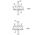
図8は、リム16の各対を各リム16の磁石20が反対方向に傾斜するように配置することによって長い通路の磁束が相殺される構成を示す。
【0030】
図9は、各リム16の磁石20が互いに反対の極性を有し、各リム16に対向する固定子コア22が互いに反対の形状を有するようにリム16の各対を配列することによって長い通路の磁束を相殺する他の構成を示している。
【0031】
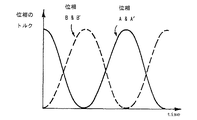
図10は、各回転子ディスク14が4つの位相を有する構成を示している。リム16の各対の位相は、電磁結合を低減するために逆位相であり、すなわち、180°の電気的位相間隔を有する。リム16の各対の回転子磁石20は、互いに逆の極性を有し、固定子コア22は、互いに反対の形状を有し、長い通路の磁束が相殺される。この構成の電気位相関係は、図11に示されており、リム16の半径方向内側の対は、トルクリップルを低減するために半径方向外側のリム16の対に対して90°位相がずれている(図12参照)。
【0032】
図10に示す構成は、トルクリップルを大幅に相殺する。トルクリップルはモータの速度及び動力の全範囲にわたって完全には解消されない。なぜならば、内側及び外側リム16は異なる全負荷トルクを生じるからである。(各リム16に生じるトルクは、直径の二乗に比例する)。しかしながら、トルクリップルの相殺が不完全であっても多ディスクの構成においては実際的な意味は少ない。なぜならば、トルクリップルの相殺は、異なるディスク14の位相方向によっても生じるからである。
【0033】
図13に示すような本発明の他の実施例において、軸12は、各々が特定の半径位置に一対のリム16を有する3つのディスク14を支持している。
【0034】
ディスク14の両側の位相は、電磁結合を低減するように逆位相であり、各対において、固定子コア22は長い通路の磁束を相殺するように反対の形状を有する。トルクリップルは、各ディスク14の位相の対を他のディスク14の位相に対して120°変位させることによって低減される。図14は、この構成における電気位相関係を示す。
【0035】
1つのディスク14に複数対のリム16を有し、各対が適当な量の位相変位を有することにより、または隣接ディスク14のリム16の対の位相を適当な量ずらせることによってトルクリップル効果を低減することができることを当業者は理解することができる。
【0036】
本発明によって製造されるモータは、いかなる数のディスク14、またはディスク14毎の複数対のリム16を有することもできる。各ディスク14の両側に複数対のリム16と固定子組立体22を使用することによって、与えられた両ディスク直径に対し、得られるトルクが増大される。
【図面の簡単な説明】
【図1】 本発明の横磁束モータの断面図である。
【図2】 図1に示す1つの回転子リムの一部の拡大図である。
【図3】 1つのモータ位相の構成を示す断面図である。
【図4】 本発明による横磁束モータに使用する固定子コアの他の実施例を示す図である。
【図5】 本発明による横磁束モータに使用する固定子コアの他の実施例を示す図である。
【図6】 本発明による固定子コアを通る短い磁束通路を示す図である。
【図7】 本発明による固定子コアを通る長い磁束通路を示す図である。
【図8】 長い通路の磁束を相殺するために一対の固定子コアの磁石が互いに反対に傾斜している構成を示す図である。
【図9】 長い通路の磁束を相殺するために一対の固定子コアが左右反対の形状を有する構成を示す図である。
【図10】 4つの位相を有する回転子ディスクの一部を示す部分図である。
【図11】 図10に示す構成の電気的な位相関係を示す図である。
【図12】 図10に示す4つの位相のトルク対時間を示すグラフである。
【図13】 各ディスクが一対の位相を有する3つのディスクを備えた横磁束モータの一部を示す部分図である。
【図14】 図13に示す構成の電気的な位相関係を示す図面である。
【符号の説明】
10 横磁束モータ
12 回転子軸
13 フランジ
14 回転子ディスク
16 回転子リム
20 磁石
22 固定子コア
24 コイル
28 固定子フレーム
31 開口部
32 端部[0001]
BACKGROUND OF THE INVENTION
The present invention relates to electrical equipment, and more particularly to synchronous equipment that operates on the principle of transverse flux.
[0002]
[Prior art]
Synchronous equipment that operates on the principle of transverse magnetic flux consists of an armature winding in the form of a circular coil that is coaxial with the rotor. The armature winding connects a magnetic flux generated by a permanent magnet attached to the rotor rim by a series of stator cores. The advantage of this configuration is that the portion of the stator core can be increased to support more magnetic flux without eroding the space required for the armature winding.
[0003]
In previous configurations of transverse flux devices, the rim of the rotor supports two rows of parallel permanent magnets separated by insulating spacers. Two circular stator coils are used, and the stator core is incorporated both inside and outside the rotor, so that effective torque is provided on both the inside and outside surfaces of the rotor.
[0004]
A problem with equipment related to this configuration is that it is difficult to assemble the stator coil so that it is surrounded by the stator core. The rotor rim is long and lacks rigidity, and the rotor is flexible due to its low rigidity against radial impacts. When the magnetic flux alternates, radial forces on the stator core cause radial movement of the stator casing. It is difficult to eliminate the vibration of the zero-order stator case without increasing the thickness of the casing.
[0005]
The configuration of the transverse flux motor has recently been improved to solve these problems.
[0006]
The improved arrangement has a rim that consists of a row of permanent magnets that span a series of stator cores. Both ends of the stator core are displaced in the radial direction so as to straddle the rim of the rotor.
[0007]
A problem with these improved transverse flux motors is that stator cores belonging to adjacent motor phases are subject to significant electromagnetic coupling, which reduces the performance of the equipment.
[0008]
It is an object of the present invention to provide a transverse flux motor that reduces the amount of electromagnetic coupling around the motor.
[Means for Solving the Problems]
An electrical apparatus according to the present invention includes a rotor including a rotor shaft rotatable around an axis and at least one disk extending from the rotor shaft and rotatable with the rotation shaft, the rotor disk comprising: At least a pair of circumferentially extending rotor rims fixed to the rotor disk, each pair of the rims being fixed at the same radial position on both sides of the rotor disk, and each rotation The child rim is composed of alternating rows of magnets and pole pieces, facing a stator assembly having a stator core adjacent to and facing the rotor rim, armature winding In a transverse flux type electrical device in which a wire is arranged in the stator core to operably excite the stator, for operation, a pair of rotor rims at a specific radial position of the rotor disk during operation of The armature windings are excited by currents of opposite phases, and the rotor magnets or the rotor magnets and the stator core in each pair of rotor rims are arranged so that the magnetic flux in the long path is canceled out. It is characterized by that.
[0009]
In one embodiment of the invention, long path magnetic flux is offset by placing each pair of rims so that the magnets of each rim have opposite polarities and the stator cores have opposite shapes. Is done.
[0010]
In the second embodiment of the present invention, the magnetic flux in the long passage is canceled by arranging the magnets of each rim to tilt in the opposite direction.
[0011]
In the electrical apparatus of the present invention having a plurality of disks, the phase of a pair of rims of one disk is shifted from the phase of a pair of rims of another disk in order to reduce torque ripple.
[0012]
In one embodiment of the present invention, an electrical device having three disks to reduce torque ripple, the phase of each rim pair is 120 ° out of phase with the other disk rim pair.
[0013]
Multiple pairs of rims are provided on each disk at different radial positions of the disk. Preferably, to reduce torque ripple, the phase of the rim pair of one disk is offset from the phase of the other rim pair of the same disk.
[0014]
In another embodiment of the invention, two pairs of rims are provided on each disk at different radial positions of the disk, and to reduce torque ripple, the phase of the radially outer pair of rims is The phase is shifted by 90 °.
[0015]
DETAILED DESCRIPTION OF THE INVENTION
Hereinafter, embodiments of the present invention will be described in detail with reference to the drawings.
[0016]
Referring to FIG. 1, a transverse flux motor, indicated by
[0017]
The rotor assembly has four rotating
[0018]
Suitable magnet materials are high energy rare earth magnet materials such as samarium cobalt and neodymium iron boron. The magnet is subdivided to limit eddy currents therein.
[0019]
The
[0020]
Opposing each
[0021]
The
[0022]
4 and 5 show differently shaped
[0023]
In operation, alternating current passes from the
[0024]
Torque ripple cancellation means that the paired phases are complementary to each other. This means a displacement in the direction of the phase, i.e. the current and the electrode or stator core are displaced between the rim pair. The phase must be 90 ° apart to cancel the torque ripple. However, at an electrical phase interval of 90 °, there is considerable electromagnetic coupling between the phases, which reduces motor performance. As a result of the electromagnetic coupling, an eddy current is generated, and a large electromagnetic loss occurs through the
[0025]
If the phases on both sides of the
[0026]
In addition, it is necessary to cancel out the long path magnetic flux by arranging the long path magnetic fluxes of adjacent rotor rims 16 to be equally opposite. If the magnetic flux in the long path is not canceled, a circular current passing through the
[0027]
The magnetic flux passing through the upper end of the
[0028]
When the magnetic flux in the long path on both sides of the
[0029]
FIG. 8 shows a configuration in which the magnetic flux of the long passage is canceled by arranging each pair of
[0030]
FIG. 9 shows a long path by arranging each pair of
[0031]
FIG. 10 shows a configuration in which each
[0032]
The configuration shown in FIG. 10 greatly cancels the torque ripple. Torque ripple is not completely eliminated over the entire range of motor speed and power. This is because the inner and
[0033]
In another embodiment of the invention as shown in FIG. 13, the
[0034]
The phases on both sides of the
[0035]
Torque ripple effect by having multiple pairs of
[0036]
A motor manufactured in accordance with the present invention may have any number of
[Brief description of the drawings]
FIG. 1 is a cross-sectional view of a transverse flux motor of the present invention.
FIG. 2 is an enlarged view of a part of one rotor rim shown in FIG.
FIG. 3 is a cross-sectional view showing a configuration of one motor phase.
FIG. 4 is a view showing another embodiment of the stator core used in the transverse magnetic flux motor according to the present invention.
FIG. 5 is a view showing another embodiment of the stator core used in the transverse magnetic flux motor according to the present invention.
FIG. 6 shows a short flux path through a stator core according to the present invention.
FIG. 7 shows a long magnetic flux path through a stator core according to the present invention.
FIG. 8 is a diagram showing a configuration in which magnets of a pair of stator cores are inclined opposite to each other in order to cancel out magnetic flux in a long passage.
FIG. 9 is a diagram showing a configuration in which a pair of stator cores have opposite left and right shapes in order to cancel out magnetic flux in a long passage.
FIG. 10 is a partial view showing a part of a rotor disk having four phases.
11 is a diagram showing an electrical phase relationship of the configuration shown in FIG.
12 is a graph showing torque versus time for the four phases shown in FIG.
FIG. 13 is a partial view showing a part of a transverse magnetic flux motor having three disks, each disk having a pair of phases.
14 is a diagram showing an electrical phase relationship of the configuration shown in FIG.
[Explanation of symbols]
DESCRIPTION OF
Claims (9)
Applications Claiming Priority (2)
| Application Number | Priority Date | Filing Date | Title |
|---|---|---|---|
| GB9516497.6 | 1995-08-11 | ||
| GBGB9516497.6A GB9516497D0 (en) | 1995-08-11 | 1995-08-11 | Electrical machine |
Publications (2)
| Publication Number | Publication Date |
|---|---|
| JPH09117117A JPH09117117A (en) | 1997-05-02 |
| JP3645663B2 true JP3645663B2 (en) | 2005-05-11 |
Family
ID=10779111
Family Applications (1)
| Application Number | Title | Priority Date | Filing Date |
|---|---|---|---|
| JP20709796A Expired - Fee Related JP3645663B2 (en) | 1995-08-11 | 1996-08-06 | Electrical equipment |
Country Status (5)
| Country | Link |
|---|---|
| EP (1) | EP0762618B1 (en) |
| JP (1) | JP3645663B2 (en) |
| DE (1) | DE69603236T2 (en) |
| ES (1) | ES2135174T3 (en) |
| GB (1) | GB9516497D0 (en) |
Cited By (2)
| Publication number | Priority date | Publication date | Assignee | Title |
|---|---|---|---|---|
| US9088199B2 (en) | 2011-08-09 | 2015-07-21 | Kabushiki Kaisha Toshiba | Motor |
| US9787144B2 (en) | 2013-07-10 | 2017-10-10 | Kabushiki Kaisha Toshiba | Rotating electrical motor using transverse magnetic flux |
Families Citing this family (10)
| Publication number | Priority date | Publication date | Assignee | Title |
|---|---|---|---|---|
| EP1005136B1 (en) * | 1998-11-27 | 2003-01-22 | Bombardier Transportation GmbH | One-phase or multiphase transversal flux machine |
| AT504456A1 (en) * | 1999-06-22 | 2008-05-15 | Bombardier Transp Gmbh | transverse flux |
| WO2003007459A1 (en) * | 2001-07-09 | 2003-01-23 | Harmonic Drive Systems Inc. | Hybrid synchronous electric machine |
| FI20050284A (en) * | 2005-03-17 | 2006-09-18 | Sulzer Pumpen Ag | agitators |
| KR100785276B1 (en) * | 2005-12-29 | 2007-12-13 | 한국전기연구원 | Permanent magnet excited transverse flux motor with out-rotor |
| KR20110093803A (en) * | 2008-11-03 | 2011-08-18 | 모터 엑셀런스, 엘엘씨 | Transverse flux electrical machine or/and commutated flux electrical machine and a method of forming a rotor for an electrical machine |
| GB0900493D0 (en) * | 2009-01-14 | 2009-02-11 | Rolls Royce Plc | Rotary transformer |
| JP5592848B2 (en) | 2011-03-30 | 2014-09-17 | 株式会社東芝 | Transverse magnetic flux type rotating electric machine and vehicle |
| CN103346651B (en) * | 2013-07-05 | 2015-08-12 | 西北工业大学 | Four phase double-faced flat-sheet formula permanent-magnetic motor with transverse magnetic field |
| JP6253520B2 (en) | 2014-05-30 | 2017-12-27 | 株式会社東芝 | Rotating electric machine |
Family Cites Families (2)
| Publication number | Priority date | Publication date | Assignee | Title |
|---|---|---|---|---|
| DE4138014C1 (en) * | 1991-11-19 | 1993-02-04 | Herbert Prof. Dr.-Ing. 3300 Braunschweig De Weh | Electromechanical power converter in rotary or linear form - has permanent magnets assembled in rotor driven by AC stator winding with pole elements |
| DE4325740C1 (en) * | 1993-07-31 | 1995-04-06 | Weh Herbert | Transversal flux machine with improved magnetic circuits |
-
1995
- 1995-08-11 GB GBGB9516497.6A patent/GB9516497D0/en active Pending
-
1996
- 1996-08-06 JP JP20709796A patent/JP3645663B2/en not_active Expired - Fee Related
- 1996-08-12 DE DE1996603236 patent/DE69603236T2/en not_active Expired - Lifetime
- 1996-08-12 EP EP19960305891 patent/EP0762618B1/en not_active Expired - Lifetime
- 1996-08-12 ES ES96305891T patent/ES2135174T3/en not_active Expired - Lifetime
Cited By (2)
| Publication number | Priority date | Publication date | Assignee | Title |
|---|---|---|---|---|
| US9088199B2 (en) | 2011-08-09 | 2015-07-21 | Kabushiki Kaisha Toshiba | Motor |
| US9787144B2 (en) | 2013-07-10 | 2017-10-10 | Kabushiki Kaisha Toshiba | Rotating electrical motor using transverse magnetic flux |
Also Published As
| Publication number | Publication date |
|---|---|
| EP0762618A1 (en) | 1997-03-12 |
| DE69603236T2 (en) | 1999-11-11 |
| EP0762618B1 (en) | 1999-07-14 |
| DE69603236D1 (en) | 1999-08-19 |
| GB9516497D0 (en) | 1995-10-11 |
| ES2135174T3 (en) | 1999-10-16 |
| JPH09117117A (en) | 1997-05-02 |
Similar Documents
| Publication | Publication Date | Title |
|---|---|---|
| US5973436A (en) | Electrical machine | |
| US20220302811A1 (en) | Multi-tunnel electric motor/generator | |
| US11784523B2 (en) | Multi-tunnel electric motor/generator | |
| JP5033552B2 (en) | Axial gap type coreless rotating machine | |
| JP5318758B2 (en) | Ring coil motor | |
| JP4653648B2 (en) | Inductor type synchronous machine | |
| EP0365535B1 (en) | Stator assembly for dynamoelectric machine | |
| US6445105B1 (en) | Axial flux machine and method of fabrication | |
| JP4468589B2 (en) | Electric machine | |
| JP3663014B2 (en) | Electrical equipment | |
| JP4890119B2 (en) | Superconducting coil device and inductor type synchronous machine | |
| JP2005500799A (en) | Unipolar transverse flux motor | |
| JP2005143276A (en) | Axial gap rotating electric machine | |
| JP3645663B2 (en) | Electrical equipment | |
| JP5610989B2 (en) | Rotating motor | |
| JP2005522972A (en) | Axial field synchronous electric machine | |
| JP2016532414A (en) | Rotor for electric machine | |
| TWI569558B (en) | Electric machine | |
| JP2016538817A (en) | Transverse flux type electric machine | |
| JP2753720B2 (en) | High efficiency motor with low torque fluctuation | |
| JPH0775302A (en) | Ring-shaped coil type three-phase claw pole type permanent magnet type electric rotary machine | |
| JP2006006032A5 (en) | ||
| JPH0746802A (en) | Electric motor | |
| JP2016086591A (en) | Outer rotor type axial gap brushless motor | |
| AU603448B2 (en) | Stator assembly for dynamoelectric machine |
Legal Events
| Date | Code | Title | Description |
|---|---|---|---|
| A131 | Notification of reasons for refusal |
Free format text: JAPANESE INTERMEDIATE CODE: A131 Effective date: 20040514 |
|
| A601 | Written request for extension of time |
Free format text: JAPANESE INTERMEDIATE CODE: A601 Effective date: 20040813 |
|
| A602 | Written permission of extension of time |
Free format text: JAPANESE INTERMEDIATE CODE: A602 Effective date: 20040818 |
|
| A521 | Written amendment |
Free format text: JAPANESE INTERMEDIATE CODE: A523 Effective date: 20041110 |
|
| A521 | Written amendment |
Free format text: JAPANESE INTERMEDIATE CODE: A821 Effective date: 20041110 |
|
| TRDD | Decision of grant or rejection written | ||
| A01 | Written decision to grant a patent or to grant a registration (utility model) |
Free format text: JAPANESE INTERMEDIATE CODE: A01 Effective date: 20050107 |
|
| A61 | First payment of annual fees (during grant procedure) |
Free format text: JAPANESE INTERMEDIATE CODE: A61 Effective date: 20050204 |
|
| R150 | Certificate of patent or registration of utility model |
Free format text: JAPANESE INTERMEDIATE CODE: R150 |
|
| FPAY | Renewal fee payment (event date is renewal date of database) |
Free format text: PAYMENT UNTIL: 20080210 Year of fee payment: 3 |
|
| FPAY | Renewal fee payment (event date is renewal date of database) |
Free format text: PAYMENT UNTIL: 20090210 Year of fee payment: 4 |
|
| FPAY | Renewal fee payment (event date is renewal date of database) |
Free format text: PAYMENT UNTIL: 20090210 Year of fee payment: 4 |
|
| FPAY | Renewal fee payment (event date is renewal date of database) |
Free format text: PAYMENT UNTIL: 20100210 Year of fee payment: 5 |
|
| FPAY | Renewal fee payment (event date is renewal date of database) |
Free format text: PAYMENT UNTIL: 20110210 Year of fee payment: 6 |
|
| FPAY | Renewal fee payment (event date is renewal date of database) |
Free format text: PAYMENT UNTIL: 20110210 Year of fee payment: 6 |
|
| FPAY | Renewal fee payment (event date is renewal date of database) |
Free format text: PAYMENT UNTIL: 20120210 Year of fee payment: 7 |
|
| FPAY | Renewal fee payment (event date is renewal date of database) |
Free format text: PAYMENT UNTIL: 20120210 Year of fee payment: 7 |
|
| FPAY | Renewal fee payment (event date is renewal date of database) |
Free format text: PAYMENT UNTIL: 20130210 Year of fee payment: 8 |
|
| LAPS | Cancellation because of no payment of annual fees |