JP3645003B2 - camera - Google Patents
camera Download PDFInfo
- Publication number
- JP3645003B2 JP3645003B2 JP10256995A JP10256995A JP3645003B2 JP 3645003 B2 JP3645003 B2 JP 3645003B2 JP 10256995 A JP10256995 A JP 10256995A JP 10256995 A JP10256995 A JP 10256995A JP 3645003 B2 JP3645003 B2 JP 3645003B2
- Authority
- JP
- Japan
- Prior art keywords
- lens
- lens frame
- lens barrel
- frame
- cam ring
- Prior art date
- Legal status (The legal status is an assumption and is not a legal conclusion. Google has not performed a legal analysis and makes no representation as to the accuracy of the status listed.)
- Expired - Fee Related
Links
- 230000003287 optical effect Effects 0.000 claims description 47
- 230000007246 mechanism Effects 0.000 description 17
- 210000000078 claw Anatomy 0.000 description 16
- 230000002093 peripheral effect Effects 0.000 description 14
- 230000000694 effects Effects 0.000 description 5
- 230000004048 modification Effects 0.000 description 3
- 238000012986 modification Methods 0.000 description 3
- 230000001105 regulatory effect Effects 0.000 description 3
- 230000008094 contradictory effect Effects 0.000 description 1
- 238000003384 imaging method Methods 0.000 description 1
Images


Classifications
-
- G—PHYSICS
- G02—OPTICS
- G02B—OPTICAL ELEMENTS, SYSTEMS OR APPARATUS
- G02B7/00—Mountings, adjusting means, or light-tight connections, for optical elements
- G02B7/02—Mountings, adjusting means, or light-tight connections, for optical elements for lenses
- G02B7/04—Mountings, adjusting means, or light-tight connections, for optical elements for lenses with mechanism for focusing or varying magnification
- G02B7/10—Mountings, adjusting means, or light-tight connections, for optical elements for lenses with mechanism for focusing or varying magnification by relative axial movement of several lenses, e.g. of varifocal objective lens
- G02B7/102—Mountings, adjusting means, or light-tight connections, for optical elements for lenses with mechanism for focusing or varying magnification by relative axial movement of several lenses, e.g. of varifocal objective lens controlled by a microcomputer
Landscapes
- Physics & Mathematics (AREA)
- Engineering & Computer Science (AREA)
- General Engineering & Computer Science (AREA)
- General Physics & Mathematics (AREA)
- Optics & Photonics (AREA)
- Structure And Mechanism Of Cameras (AREA)
Description
【0001】
【産業上の利用分野】
本発明は、カメラ、より詳しくは、撮影位置と該位置よりも本体側の繰り込み位置との間で移動可能なレンズ鏡枠を有するカメラに関する。
【0002】
【従来の技術】
近年、カメラは小型化を要求されていて、しかも、カメラを持ち運ぶ際などには、携帯性を低下させるような突起等がカメラ本体から突出しているのはあまり望ましくないとされる傾向にある。
【0003】
しかしながら、所定の性能を満たした撮影レンズとするためには、光軸方向にある程度の長さが要求されるために、上記小型化を満たすのは困難である。さらに、最近では高倍率ズームが好まれる傾向にあるために、撮影レンズを収納するレンズ鏡枠も一層光軸方向に長くならざるを得なかった。
【0004】
上述のようなカメラの小型化と撮影レンズの大型化という一見相反する要求を満たすものとして、従来より、撮影を行う際にはカメラ本体から突出した撮影位置に移動し、一方、携帯時などの撮影を行わない際には上記撮影位置よりも本体側に収納された位置である繰り込み位置に移動することが可能なレンズ鏡枠を有するカメラが提案されており、これらには種々のものがある。
【0005】
このようなものの一例としては、たとえば実開昭61−188112号公報に、テレからワイドへズーミング動作を行う延長上でさらに該ズーミング動作を続けることにより、レンズ鏡枠が沈胴してカメラ本体内に収納されるものが記載されている。
【0006】
【発明が解決しようとする課題】
しかしながら、上記実開昭61−188112号公報に記載のものでは、撮影状態にあるレンズ鏡枠を、光軸前方側から例えば手などで後方側に向けて押圧すると、該レンズ鏡枠内に設けられたカム環が回転してしまうことによりズーミング動作が行われてレンズ鏡枠が沈胴してしまい、撮影が不可能な状態となることがある。
【0007】
本発明は上記事情に鑑みてなされたものであり、撮影位置にあるときは外力を受けても光軸方向に移動することがないレンズ鏡枠を備えたカメラを提供することを目的としている。
【0008】
【課題を解決するための手段】
上記目的を達成するために、本発明のカメラは、撮影レンズを移動可能に有していて、撮影位置と該位置よりも本体側の繰り込み位置との間で移動する第1の鏡枠と、上記第1の鏡枠とともに光軸方向に移動可能で、該第1の鏡枠に対して回転することにより上記撮影レンズを上記光軸方向に駆動させる第2の鏡枠と、上記第1の鏡枠が上記撮影位置に移動した後、上記第2の鏡枠の回転により、上記カメラ本体と上記第1の鏡枠若しくは上記第2の鏡枠とが係合して上記第1の鏡枠の光軸方向の移動を規制する鏡枠位置規制手段とを具備する。
【0011】
【作 用】
請求項1による本発明のカメラは、撮影レンズを有する第1の鏡枠が撮影位置と該位置よりも本体側の繰り込み位置との間で移動し、第2の鏡枠が上記第1の鏡枠とともに光軸方向に移動し該第1の鏡枠に対して回転することにより上記撮影レンズを上記光軸方向に駆動させ、鏡枠位置規制手段は、上記第1の鏡枠が上記撮影位置に移動した後、上記第2の鏡枠の回転により該第1の鏡枠の光軸方向の移動を規制する。
【0014】
【実施例】
以下、図面を参照して本発明の実施例を説明する。
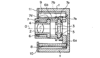
図1から図5は本発明の第1実施例を示したものであり、図1は収納時におけるレンズ鏡枠を示す光軸に沿った断面図、図2は上半分がワイド時、下半分がテレ時における撮影可能な状態のレンズ鏡枠を示す光軸に沿った断面図である。
【0015】
この実施例における光学系は、正の屈折力を有する第1のレンズ群2と、負の屈折力を有する第2のレンズ群3とを有してなり、いわゆる2群ズームレンズを構成している。
【0016】
上記第1のレンズ群2と第2のレンズ群3は、それぞれ1群枠4および2群枠5に保持されている。
【0017】
これら1群枠4と2群枠5は、その周面に突設されたピンが、第1の鏡枠たる移動枠6に穿設された直進孔6bを貫通することにより、該移動枠6に対して、光軸Oの方向に直進移動可能となるように保持されている。
【0018】
上記移動枠6の外周側には、回動可能となるようにカメラ本体1に保持された第2の鏡枠たるカム環7が設けられていて、このカム環7の内周面には、上記1群枠4の周面から突設されたピンが係合するカム溝7dと、上記2群枠5の周面から突設されたピンが係合するカム溝7eとがそれぞれ刻設されている。
【0019】
これにより、カム環7を回転することで、図2に示すように、ワイドとテレの間をズーミングすることができるようになっている。
【0020】
一方、この実施例におけるレンズ鏡枠は、図1に示すような、上記ワイド状態よりもさらに繰り込んで全長を縮めたコンパクトな収納状態に移行することが可能となっている。
【0021】
すなわち、上記カメラ本体1の前端部には鏡枠位置規制手段であり鏡枠係止手段たるロック爪11が取り付けられており、このロック爪11とカメラ本体1との間には第2の駆動手段たるズームギヤー9が回転可能に保持されている。
【0022】
このズームギヤー9は、上記カム環7の後端部周面に設けられた歯車7aと噛合して、該カム環7を回動するためのものである。さらにこのカム環7の歯車7aの前方近傍には、後で詳しく説明するように、上記ロック爪11と係合するためのリブ7bが周方向に形成されている。
【0023】
また、上記カメラ本体1の前端部には押え板10が取り付けられており、この押え板10とカメラ本体1との間には第1の駆動手段たる送りねじ軸8が回転可能に保持されている。
【0024】
この送りねじ軸8は、上記移動枠6の後端部に螺刻された雌ねじ部6aと噛合して、該移動枠6を光軸Oの方向に進退させるものである。
【0025】
これにより、この送りねじ軸8が回転すると、移動枠6は、カメラ本体1の内部に繰り込まれた位置である収納位置と、この収納位置から繰り出された位置である所定位置との間を、光軸Oの方向に進退して移動することが可能となっている。
【0026】
移動枠6が、上記所定位置にあるときにズームギヤー9を回転させると、カム環7が回転して撮影可能状態の内のワイド状態に移行し、さらに回転させることによりズーミングが行われてテレ状態に移行するようになっている。
【0027】
次に、上記図1および図2、さらに図3から図5を参照して、本実施例におけるレンズ鏡枠のロック機構を説明する。
【0028】
図3から図5はロック爪11とカム環7のリブ7bの位置関係を示したものであり、図3はカム環が収納位置に回転したとき、図4はカム環がワイド位置に回転したとき、図5はカム環がテレ位置に回転したときの状態をそれぞれ示したものである。
【0029】
まず、収納状態から撮影可能状態へのレンズ鏡枠の繰り出しについて説明する。
【0030】
図1に示すような収納状態において、送りねじ軸8が回転すると、移動枠6によってレンズ鏡枠が光軸Oの方向に移動して所定位置に達する。
【0031】
すなわち、カム環7のリブ7bには、図3に示すような略矩形の切欠部7cが形成されていて、この切欠部7cによりロック爪11を通過させることで、該リブ7bは、ロック爪11の前方となる所定位置まで移動する。このカム環7における所定位置とは、回転方向の位置は上記収納位置と同じとなり、光軸方向の位置は撮影可能状態と同じとなる位置である。
【0032】
このような所定位置の状態となったら、次に、ズームギヤー9を回転させることによって、回転位置が収納位置のままであったカム環7を図4に示すようなワイド位置に回転させる。これにより、レンズ鏡枠は、図2の上半分に示すようなワイド状態にセットされる。
【0033】
このワイド状態においては、ロック爪11は、図2および図4に示すように、リブ7bと歯車7aの間に保持されることになり、例えば外力を受けた場合においても、カム環7の光軸方向の位置を保つことが可能となる。
【0034】
上記ワイド状態からさらにズームギヤー9を回転させると、1群枠4および2群枠5がカム環7のカム溝7d,7eに沿って光軸方向に移動して、図5に示すようなテレ状態へ向かう。
【0035】
こうしてカム環7がテレ状態となった場合にも、図2および図5に示すように、ロック爪11がリブ7bと歯車7aの間に保持されたままの状態であるので、該カム環7の光軸方向の位置は、同様に維持される。
【0036】
次に、上記撮影可能状態から収納する場合には、全く逆に、まずカム環7を上記と逆方向にテレ側からワイド側へ回転させて、さらに図3に示すような所定位置まで戻し、次に、送りねじ軸8をやはり上記と逆方向に回転させることによりレンズ鏡枠をカメラ本体1の内部に繰り込んで収納位置に戻す。
【0037】
なお、本実施例では、ロック爪11を通過させるための切欠部7cを、カム環7のリブ7bに1つ設けたが、これに限るものではなく、複数設けてもよい。
【0038】
また、本実施例では、カム環7のリブ7bと歯車7aとでロック爪11を挟み込むことにより保持するように構成したが、リブ7bと歯車7aの間に他のリブを設けて、これら2つのリブの間にロック爪11を挟みこむように構成しても構わない。
【0039】
このような第1実施例によれば、レンズ鏡枠が撮影位置にある場合には、その光軸方向の位置は保持されているので、例え外力を加えられた場合であっても、該レンズ鏡枠が撮影不能となる収納位置に移動してしまうことはなく、不本意な動作を行うことがない。
【0040】
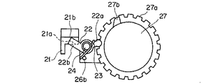
図6から図12は本発明の第2実施例を示したものであり、図6は収納時におけるレンズ鏡枠を示す正面図、図7は収納時におけるレンズ鏡枠の半分を示す光軸に沿った断面図、図8はワイド時におけるレンズ鏡枠を示す正面図、図9はワイド時におけるレンズ鏡枠の半分を示す光軸に沿った断面図である。
【0041】
この第2実施例において、上述の第1実施例と同様である部分については同一の符号を付して説明を省略し、主として異なる点についてのみ説明する。
【0042】
この実施例のカメラのレンズ鏡枠には、ズームギヤー9,送りねじ軸8等の、レンズ鏡枠のズーミングと収納位置とワイド位置の間の移動に関する機構も、図示はしないが上述の第1実施例と同様に設けられている。
【0043】
次に、ロック機構について説明する。
【0044】
この実施例のカメラ本体21,第1の鏡枠たる移動枠26,第2の鏡枠たるカム環27は、上述の第1実施例におけるカメラ本体1,移動枠6,カム環7とほぼ同様に構成されているが、ロック機構に関する部分のみが異なっている。
【0045】
すなわち、カム環27には、歯車27aが周方向に設けられるとともに、鏡枠位置規制手段であり鏡枠係止手段たるロック板22を駆動するための突起27bが周面から突設されている。この突起27bは、正面からみたときの形状が略台形になるように形成されていて、その一方の側面には、傾斜がより緩やかな斜面27cが設けられている。
【0046】
また、移動枠26は、後端部が一旦外周方向に突出した後、再び前方に向かって曲折しており、断面が図7に示すようにコの字状に形成されている。そして、このコの字形状をなす部分の先端部に、ロック板22が、光軸Oと平行な方向に植立された軸24によって回動自在に取り付けられている。
【0047】
このロック板22は、先端部に係合用の円形部が形成された駆動用腕部22aと、この駆動用腕部22aの反対方向からやや傾斜して突設された略矩形の腕部でなるロック用腕部22bとを有してなる。
【0048】
上記軸24には例えばコイルばねでなるロックばね23が挿通されていて、その一端をロック板22の駆動用腕部22aに掛けるとともに、他端を移動枠26に植立されたピンでなるばね掛け26bに掛けることによって、ロック板22を図6中時計周りに付勢するようになっている。
【0049】
また、上記ロック板22のロック用腕部22bが当接可能なカメラ本体21の位置には、光軸方向に長いリブ状の受部21aが内径方向に突設されるとともに、その先端側に略矩形のストッパ部21bが設けられている。
【0050】
次に、この第2実施例のロック機構の作用を説明する。
【0051】
図6に示すように、カム環27の回転位置が収納状態であるときは、ロック板22は、駆動用腕部22aが、カム環27の突起27bに乗り上げた状態でロックばね23の付勢力により当接している。
【0052】
この状態ではロック板22のロック用腕部22bは、カメラ本体21の受部21aとは接触していない。それゆえに、図示しない送りねじ軸を回転させることにより、移動枠26を収納状態から所定位置まで光軸方向に移動させても、この移動の動作が何等阻止されることはない。
【0053】
こうしてレンズ鏡枠が繰り出されて所定位置になったときには、ロック板22のロック用腕部22bは、カメラ本体21の受部21aを過ぎて、ストッパ部21bに当接可能な位置に達している。
【0054】
このような所定位置になると、図示しないズームギヤーを回転させることにより、カム環27が光軸周りに回転する。こうしてカム環27がワイド位置まで回転して撮影可能となった状態を、図8および図9に示す。
【0055】
カム環27がワイド位置まで回転すると、カム環の突起27bは、ロック板22の腕部22aと当接する位置からはすでに移動して過ぎている。すると、ロック板22は、ロックばね23の付勢力により時計周りに回転して、図8に示すように、カメラ本体21のストッパ部21bに、ロック用腕部22bが当接した状態で保持される。
【0056】
この状態では、ロック板22のロック用腕部22bは、カメラ本体21の受部21aに対して、光軸方向に対向して接触する位置となっている。それゆえに、この状態においてレンズ鏡枠を前方から外力により押圧されたとしても、ロック板22が、カメラ本体21の受部21aに当接してその光軸方向の位置を規制するために、レンズ鏡枠が収納方向に繰り込まれてしまうことはない。
【0057】
この位置規制は、カム環27をさらに回転させてテレ状態になったときも、同様に維持される。
【0058】
次に、レンズ鏡枠をカメラ本体21の内部に収納するときの動作について説明する。
【0059】
カム環27を上述とは逆方向に回転させることにより、ワイド位置から所定位置まで回転する。
【0060】
このとき、ロック板22は、駆動用腕部22aがカム環27の斜面27cに沿って突起27bに乗り上げることにより、図8中反時計周りに回転させられる。これにより、ロック用腕部22が受部21aおよびストッパ部21bから外れて、カメラ本体21とロック板22の係合が解かれる。
【0061】
この状態となったら、図示しない送りねじ軸を繰り出し時とは反対方向に回転させることにより、レンズ鏡枠がカメラ本体21の内部に収納される。
【0062】
なお、本実施例では、レンズ鏡枠を繰り出したときに、ロック板22が回転するのを係止するためのストッパ部21bを設けたが、該ストッパ部21bを設けなくても、例えば図10に示すように、カメラ本体21の上記受部21aを斜面21dとして形成すれば、ロック板22とカメラ本体21をガタなく位置決めすることができる。
【0063】
また、本実施例では、繰り込み方向の外力を受けた場合に対応する構成だけを示しているが、例えば図11に示すように、カメラ本体21にコの字状の溝をなす受部21eを形成すれば、繰り込み方向および繰り出し方向の両方向について、レンズ鏡枠が移動するのをロックすることが可能となる。
【0064】
この場合にも、図12に示すように、両側に斜面を有する受部21fとして形成すれば、繰り出し方向および繰り込み方向の両方向に対して、ガタなく位置決めすることができる。
【0065】
あるいは、受部21eは上記図11に示したような形状のまま両側面を垂直にしておいて、この受部21eに当接するロック板22の側面を斜面に形成しても、同様の効果を奏することができる。さらには、受部21eとロック板22の両方を斜面に形成すれば、接触する部分の面積が増して、より大きな外力に耐えられるようになってよい。
【0066】
加えて、ロック板22の側に溝状の受部を形成して、カメラ本体21の側にリブ等の突出する部分を形成してもよいことはいうまでもない。
【0067】
係止力をさらに高めるために、上述のようなロック機構を、移動枠26の複数箇所に設けることも、もちろん可能である。
【0068】
このような第2実施例によれば、上述の第1実施例とほぼ同様の効果を奏するとともに、該第1実施例においては、リブと歯車の間にロック爪を挟みこんで係止していたので、ズーミング中に外力を受けた場合にはカム環との間に摩擦力が発生してズーミングの負荷が増大してしまう可能性があったが、本実施例によれば、外力をカメラ本体と移動枠で受けるようにしたために、ズーミング時の負荷が増大することはない。
【0069】
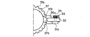
図13から図18は本発明の第3実施例を示したものであり、図13は収納時のレンズ鏡枠を示す正面図、図14は収納時のレンズ鏡枠の半分を示す断面図、図15はレンズ鏡枠が所定位置に繰り出されてかつカム環が収納状態にあるときの正面図、図16はレンズ鏡枠が所定位置に繰り出されてかつカム環が収納状態にあるときの断面図、図17はレンズ鏡枠が所定位置に繰り出されてかつカム環がワイド状態にあるときの正面図、図18はレンズ鏡枠が所定位置に繰り出されてかつカム環がワイド状態にあるときの断面図である。
【0070】
この第3実施例において、上述の第1,第2実施例と同様である部分には同一の符号を付して説明を省略し、主として異なる点についてのみ説明する。
【0071】
この実施例のカメラのレンズ鏡枠には、ズームギヤー9,送りねじ軸8等の、レンズ鏡枠のズーミングと収納位置とワイド位置の間の移動に関する機構も、図示はしないが上述の第1実施例と同様に設けられている。
【0072】
次に、ロック機構について説明する。
【0073】
この実施例のカメラ本体31,第1の鏡枠たる移動枠36,第2の鏡枠たるカム環37は、上述の第1実施例におけるカメラ本体1,移動枠6,カム環7とほぼ同様に構成されているが、ロック機構に関する部分のみが異なっている。
【0074】
すなわち、この第3実施例は、上述の第2実施例でレンズ鏡枠の移動枠26に設けたロック板22を、カメラ本体側に設けたものである。
【0075】
カメラ本体31の取付部31aには、光軸Oに垂直な方向の軸34が植立されていて、この軸32には鏡枠位置規制手段であり鏡枠係止手段たるロックレバー32が回動可能に取り付けられている。
【0076】
このロックレバー32は、その先端部から内径方向に向けて突起部32aを突設するとともに、この突起部32aの光軸やや後方(図14の上方)の側面には矩形状の溝32cが形成されている。
【0077】
上記軸34には、例えばコイルばねでなるロックばね33が挿通されていて、その一端をロックレバー32に掛けるとともに、他端をカメラ本体31に掛けることによって、該ロックレバー32を図14中時計周りに付勢するようになっている。
【0078】
また、移動枠36の光軸方向の後端側からは、上記ロックレバー32の回転を規制するための突起部36aが、外周方向に向かって突設されている。
【0079】
カム環37は、歯車37aが周方向に設けられるとともに、ロックレバー32の回転位置を規制するための突起37bが周面から突設されている。この突起37bは、正面からみたときの形状が略台形になるように形成されていて、その一方の側面には傾斜がより緩やかな斜面37dが図13に示すように設けられ、さらに光軸前方側の面にも、傾斜が緩やかな斜面37cが図14に示すように設けられている。
【0080】
次に、この第3実施例のロック機構の作用を説明する。
【0081】
図13,図14に示すような、レンズ鏡枠がカメラ本体31に収納された状態では、ロックレバー32は、その軸34周りの図14中時計方向の回転を移動枠36に設けられた突起部36aにより規制されるために、先端に設けられた駆動用の突起部32aがカム環37に接触することはない。
【0082】
これにより、レンズ鏡枠を繰り出しているときに、カム環37に突起部32aが接触して擦れるようなことはなく、スリ傷等がつくことはない。
【0083】
図示しない送りねじ軸を回転することによりレンズ鏡枠を光軸方向に繰り出して行くと、ロックレバー32の突起部32aは、カム環37の周面から突設された突起37bの斜面37cに当接する。
【0084】
さらにレンズ鏡枠を所定の位置まで繰り出すと、ロックレバー32の突起部32aは、図15,図16に示すように斜面37cに沿って突起37bに乗り上げる状態となる。
【0085】
このときには、ロックレバー32は、カム環37の突起37bにより、軸34周りの図14中時計方向の回転を規制されることになる。
【0086】
次に、図示しないズームギヤーが回転して、カム環37が収納位置からワイド位置に回転されると、その突起37bは、図15の時計方向に回転されて、ロックレバー32の突起部32aと当接する位置から退避する。
【0087】
これによりロックレバー32は、ばね33の付勢力によって図18中時計周りに回転して、図17,図18に示すように、該ロックレバー32の溝32cが移動枠36の突起部36aと係合して、同移動枠36の光軸方向の移動を規制する。
【0088】
なお、このときには突起部32aと歯車37aおよびカム環37の周面との間には隙間が形成されるようになっていて、これらが互いに直接接触することはないために、ズーミングにおけるカム環37の回転が阻害されることはない。
【0089】
次に、レンズ鏡枠をカメラ本体31の内部に収納するときの動作について説明する。
【0090】
レンズ鏡枠を収納するときは、図示しないズームギヤーを上述とは逆方向に回転することにより、まずカム環37を収納位置まで回転させる。このとき、ロックレバー37は、上記斜面37dに沿って突起37bに乗り上げることにより、図18中反時計周りに回転させられて、図16に示すような所定位置の状態になる。
【0091】
この状態になったら、図示しない送りねじ軸を繰り出すときと反対方向に回転することにより、図14に示すように、レンズ鏡枠がカメラ本体31の内部に収納される。
【0092】
なお、ロックレバー32の溝32cと移動枠37の突起37bは、上述の第2実施例で説明したロック板22とカメラ本体21のように、そのどちらか一方、または両方を斜面とすることで、ガタのないロック機構とすることができる。
【0093】
また、本実施例に示したような機構も、複数箇所に設けても良いのはいうまでもなく、さらに、上記第1から第3実施例の構成を、それぞれ自由に組合わせて使用することも可能である。
【0094】
このような第3実施例によれば、上述の第1実施例とほぼ同様の効果を奏するとともに、第2実施例と同様に、外力がズーミング駆動に影響を及ぼすことのない機能性に優れたロック機構となる。
【0095】
本発明のカメラにおけるレンズ鏡枠のロック機構は、あくまでもレンズ鏡枠が外力を受けたときの安全機構であるので、何らかの原因で本機構が故障した場合でも、撮影が可能であることが望まれる。上述の第2,第3実施例において、ロックを掛けるときにはばねの付勢力により従動させて行い、一方、ロックを解除するときにはレンズ鏡枠の動作に連動して強制的に行うようにしているのは、このためである。
【0096】
すなわち、ロックが解除されている状態において、万が一、ロック板またはロックレバーが動作しなくなった場合でも、レンズ鏡枠の繰り出しや繰り込み、あるいはズーミング等は、全く正常に行うことができる。
【0097】
また、ロックされている状態において、ロック板またはロックレバーが動作しなくなった場合には、レンズ鏡枠がカメラ本体内に収納されことも有り得るが、ズーミング動作は支障なく行うことができる。
【0098】
一方、ロックを掛けるときの動作を、レンズ鏡枠の動作に連動して強制的に行うようにした場合には、ロックが解除されている状態において、ロック板またはロックレバーが動作しなくなると、ズーミングを行うことが不可能になってしまう。
【0099】
このような理由により、上記第2,第3実施例では、ロックを掛けるときの動作は、ばねの付勢力等により従動するようにしたものである。
【0100】
ただし、カメラの性質上、外力を受けてレンズ鏡枠が引込んでしまうことが絶対に許されない場合には、ロックを強制的に行い、一方、ロックの解除をばね力により従動して行うようにしても良いし、あるいはロックの係止と解除の両方を強制的に行うようにしてももちろんかまわない。
【0101】
上述の第1から第3実施例のいずれにおいても、収納動作とズーミング動作を利用したロック機構としたが、これに限るものではなく、ズーミング動作の代わりに例えばフォーカシング動作やあるいは焦点距離切替動作を利用してもよく、この場合にもほぼ同様の構成を適用することにより、同様の効果を奏することができる。
【0102】
[付記]
以上詳述したような本発明の上記実施態様によれば、以下のごとき構成を得ることができる。
【0103】
(1) 撮影レンズを有する第1の鏡枠と、
上記第1の鏡枠とともに移動可能で、該第1の鏡枠に対して回転することにより上記撮影レンズを光軸方向に駆動させる第2の鏡枠と、
上記第1の鏡枠を撮影位置と該位置よりも本体側の繰り込み位置との間で移動させる第1の駆動手段と、
上記第1の鏡枠が撮影位置に移動した後に、該第1の鏡枠と一体的に設けられた上記第2の鏡枠を回転させる第2の駆動手段と、
駆動された上記第2の鏡枠の位置によって、該第2の鏡枠の移動を許容するか、またはカメラ本体に対して該第2の鏡枠が光軸方向に移動するのを規制する鏡枠ロック手段と、
を具備したことを特徴とするカメラ。
【0104】
(2) 上記撮影レンズは焦点位置調節レンズであって、上記第2の駆動手段は焦点位置調節手段であることを特徴とする付記1に記載のカメラ。
【0105】
(3) 上記撮影レンズは焦点距離調節レンズを含んでいて、上記第2の駆動手段は焦点距離調節手段であることを特徴とする付記1に記載のカメラ。
【0106】
(4) 上記鏡枠ロック手段は、
カメラ本体に設けられたロック部材と、
上記第2の鏡枠に設けられていて、上記第1の鏡枠が光軸方向に移動する際には上記ロック部材の通過を許容する切欠部と、該第2の鏡枠が所定の位置に回転した際には該ロック部材とともに該第2の鏡枠の光軸方向の移動を阻止する溝部とを有するフランジ手段と、
を有してなることを特徴とする付記1に記載のカメラ。
【0107】
(5) 上記鏡枠ロック手段は、
上記第2の鏡枠の外周面に設けられた突起手段と、
上記第1の鏡枠に設けられていて、上記第2の鏡枠の回転に伴う上記突起手段の回転に連動して該第2の鏡枠の光軸方向の移動を許容する位置と光軸上の移動を阻止する位置とに移動可能なロック部材と、
を有してなることを特徴とする付記1に記載のカメラ。
【0108】
(6) 上記鏡枠ロック手段は、
上記第1の鏡枠と係合する係合部と上記第2の鏡枠の外周面方向に向かって設けられた突起手段とを有していて、カメラ本体に対して該第1の鏡枠と係合する係合位置とこの係合を解除する解除位置とに回動するロックレバーと、
上記第2の鏡枠の外周面に設けられていて、この第2の鏡枠が第1の位置へ回転した際には上記第1の鏡枠と上記ロックレバーとの係合を解除するとともに第1の鏡枠の移動を可能とし、上記第2の位置へ回転した際には上記第1の鏡枠と上記ロックレバーとが係合することによってその移動を阻止するカム手段と、
を有してなることを特徴とする付記1に記載のカメラ。
【0109】
【発明の効果】
以上説明したように本発明のカメラによれば、レンズ鏡枠が撮影位置にあるときは、外力を受けても光軸方向に移動することがない。
【図面の簡単な説明】
【図1】本発明の第1実施例において、収納時におけるレンズ鏡枠を示す光軸に沿った断面図。
【図2】上記第1実施例において、上半分がワイド時、下半分がテレ時における撮影可能な状態のレンズ鏡枠を示す光軸に沿った断面図。
【図3】上記第1実施例において、収納位置に回転したときのカム環のリブとロック爪との位置関係を示す正面図。
【図4】上記第1実施例において、ワイド位置に回転したときのカム環のリブとロック爪との位置関係を示す正面図。
【図5】上記第1実施例において、テレ位置に回転したときのカム環のリブとロック爪との位置関係を示す正面図。
【図6】本発明の第2実施例において、収納時におけるレンズ鏡枠を示す正面図。
【図7】上記第2実施例において、収納時におけるレンズ鏡枠の半分を示す光軸に沿った断面図。
【図8】上記第2実施例において、ワイド時におけるレンズ鏡枠を示す正面図。
【図9】上記第2実施例において、ワイド時におけるレンズ鏡枠の半分を示す光軸に沿った断面図。
【図10】上記第2実施例において、カメラ本体の受部の第1変形例を示す平面図。
【図11】上記第2実施例において、カメラ本体の受部の第2変形例を示す平面図。
【図12】上記第2実施例において、カメラ本体の受部の第3変形例を示す平面図。
【図13】本発明の第3実施例において、収納時のレンズ鏡枠を示す正面図。
【図14】本発明の第3実施例において、収納時のレンズ鏡枠の半分を示す断面図。
【図15】本発明の第3実施例において、レンズ鏡枠が所定位置に繰り出されてかつカム環が収納状態にあるときの、該レンズ鏡枠の半分を示す正面図。
【図16】本発明の第3実施例において、レンズ鏡枠が所定位置に繰り出されてかつカム環が収納状態にあるときの、該レンズ鏡枠の半分を示す断面図。
【図17】本発明の第3実施例において、レンズ鏡枠が所定位置に繰り出されてかつカム環がワイド状態にあるときの、該レンズ鏡枠の半分を示す正面図。
【図18】本発明の第3実施例において、レンズ鏡枠が所定位置に繰り出されてかつカム環がワイド状態にあるときの、該レンズ鏡枠の半分を示す断面図。
【符号の説明】
1,21,31…カメラ本体
6,26,36…直進枠(第1の鏡枠)
7,27,37…カム環(第2の鏡枠)
8…送りねじ軸(第1の駆動手段)
9…ズームギヤー(第2の駆動手段)
11…ロック爪(鏡枠位置規制手段,鏡枠係止手段)
22…ロック板(鏡枠位置規制手段,鏡枠係止手段)
32…ロックレバー(鏡枠位置規制手段,鏡枠係止手段)[0001]
[Industrial application fields]
The present invention relates to a camera, and more particularly to a camera having a lens barrel that is movable between a photographing position and a retracted position closer to the main body than the position.
[0002]
[Prior art]
In recent years, cameras have been required to be miniaturized, and when carrying the camera, it tends to be less desirable that protrusions that reduce portability protrude from the camera body.
[0003]
However, since a certain length is required in the optical axis direction in order to obtain a photographing lens satisfying a predetermined performance, it is difficult to satisfy the downsizing. Furthermore, recently, since there is a tendency to favor high-power zooming, the lens barrel that houses the taking lens must be further elongated in the optical axis direction.
[0004]
In order to satisfy the seemingly contradictory demands of downsizing the camera and increasing the size of the photographic lens as described above, the camera has moved to a shooting position protruding from the camera body when taking a picture. There has been proposed a camera having a lens barrel that can move to a retraction position that is a position housed on the main body side relative to the shooting position when shooting is not performed. .
[0005]
As an example of this, for example, in Japanese Utility Model Laid-Open No. 61-188112, by continuing the zooming operation on the extension for performing the zooming operation from tele to wide, the lens barrel is retracted into the camera body. What is stored is described.
[0006]
[Problems to be solved by the invention]
However, in the one described in Japanese Utility Model Laid-Open No. 61-188112, when the lens barrel in the photographing state is pressed from the front side of the optical axis toward the rear side, for example, by hand, the lens barrel is provided in the lens barrel. When the cam ring is rotated, a zooming operation is performed and the lens barrel is retracted, which may make it impossible to photograph.
[0007]
The present invention has been made in view of the above circumstances, and an object of the present invention is to provide a camera including a lens barrel that does not move in the optical axis direction even when an external force is applied when in an imaging position.
[0008]
[Means for Solving the Problems]
In order to achieve the above object, the camera of the present invention has a taking lens.MoveableA first lens frame that moves between a photographing position and a retraction position closer to the main body than the position, and is movable in the optical axis direction together with the first lens frame. A second lens frame that drives the photographic lens in the direction of the optical axis by rotating with respect to the frame; and after the first lens frame has moved to the photographic position, the second lens frame is rotated by the rotation of the second lens frame.The camera body engages with the first lens frame or the second lens frame.A lens frame position restricting means for restricting movement of the first lens frame in the optical axis direction;To do.
[0011]
[Operation]
In the camera according to the first aspect of the present invention, the first lens frame having the photographing lens moves between the photographing position and the retraction position on the main body side with respect to the position, and the second lens frame is the first mirror. The photographic lens is moved by moving in the optical axis direction together with the frame and rotating with respect to the first lens frame.the aboveThe lens frame position restricting means is driven in the optical axis direction, and the first lens frame isthe aboveMoved to shooting positionAfterSecond turn of the lens frameIn turnMore than1The movement of the lens frame in the optical axis direction is restricted.
[0014]
【Example】
Embodiments of the present invention will be described below with reference to the drawings.
FIGS. 1 to 5 show a first embodiment of the present invention. FIG. 1 is a sectional view taken along the optical axis of the lens barrel when housed, and FIG. 2 is a lower half when the upper half is wide. FIG. 5 is a cross-sectional view along the optical axis showing a lens barrel in a telephoto-capable state.
[0015]
The optical system in this embodiment has a
[0016]
The
[0017]
The
[0018]
On the outer peripheral side of the moving
[0019]
Accordingly, by rotating the
[0020]
On the other hand, the lens barrel in this embodiment can be shifted to a compact storage state that is further retracted than the wide state and has a reduced overall length as shown in FIG.
[0021]
That is, a
[0022]
The
[0023]
A
[0024]
The
[0025]
Thus, when the
[0026]
When the
[0027]
Next, referring to FIGS. 1 and 2 and FIGS. 3 to 5, the lens frame locking mechanism in the present embodiment will be described.
[0028]
3 to 5 show the positional relationship between the
[0029]
First, the extension of the lens barrel from the housed state to the photographable state will be described.
[0030]
When the
[0031]
That is, the
[0032]
When this state is reached, the
[0033]
In this wide state, as shown in FIGS. 2 and 4, the
[0034]
When the
[0035]
Even when the
[0036]
Next, when storing from the above-mentioned photographing enabled state, on the contrary, first, the
[0037]
In the present embodiment, one
[0038]
In the present embodiment, the
[0039]
According to the first embodiment, when the lens barrel is at the photographing position, the position in the optical axis direction is maintained, so that even when an external force is applied, the lens The mirror frame does not move to the storage position where the photographing is impossible, and no unintentional operation is performed.
[0040]
6 to 12 show a second embodiment of the present invention. FIG. 6 is a front view showing the lens barrel when stored, and FIG. 7 is an optical axis showing half of the lens barrel when stored. FIG. 8 is a front view showing the lens barrel when wide, and FIG. 9 is a cross-sectional view along the optical axis showing half of the lens barrel when wide.
[0041]
In the second embodiment, the same parts as those in the first embodiment are denoted by the same reference numerals, description thereof is omitted, and only different points will be mainly described.
[0042]
In the camera lens barrel of this embodiment, the
[0043]
Next, the lock mechanism will be described.
[0044]
The
[0045]
That is, the
[0046]
Further, the moving
[0047]
The
[0048]
A
[0049]
In addition, a rib-shaped receiving
[0050]
Next, the operation of the lock mechanism of the second embodiment will be described.
[0051]
As shown in FIG. 6, when the rotational position of the
[0052]
In this state, the locking
[0053]
Thus, when the lens barrel is extended to the predetermined position, the locking
[0054]
At such a predetermined position, the
[0055]
When the
[0056]
In this state, the locking
[0057]
This position restriction is similarly maintained when the
[0058]
Next, an operation when the lens barrel is housed in the
[0059]
By rotating the
[0060]
At this time, the
[0061]
When this state is reached, the lens barrel is housed inside the
[0062]
In this embodiment, the
[0063]
Further, in this embodiment, only the configuration corresponding to the case where an external force in the retraction direction is received is shown. However, as shown in FIG. 11, for example, a receiving
[0064]
Also in this case, as shown in FIG. 12, if it is formed as a receiving
[0065]
Alternatively, the same effect can be obtained even when the receiving
[0066]
In addition, it goes without saying that a groove-shaped receiving portion may be formed on the
[0067]
Of course, in order to further increase the locking force, it is possible to provide the lock mechanisms as described above at a plurality of locations of the moving
[0068]
According to the second embodiment, the same effect as that of the first embodiment described above can be obtained. In the first embodiment, the locking claw is sandwiched between the rib and the gear to be locked. Therefore, when an external force is applied during zooming, a frictional force may be generated between the cam ring and the zooming load may increase, but according to this embodiment, the external force is applied to the camera. Since it is received by the main body and the moving frame, the load during zooming does not increase.
[0069]
FIGS. 13 to 18 show a third embodiment of the present invention, FIG. 13 is a front view showing the lens barrel when stored, and FIG. 14 is a cross-sectional view showing half of the lens barrel when stored, 15 is a front view when the lens barrel is extended to a predetermined position and the cam ring is in a retracted state, and FIG. 16 is a cross-section when the lens barrel is extended to a predetermined position and the cam ring is in a retracted state. 17 is a front view when the lens barrel is extended to a predetermined position and the cam ring is in a wide state. FIG. 18 is a view when the lens barrel is extended to a predetermined position and the cam ring is in a wide state. FIG.
[0070]
In the third embodiment, parts similar to those in the first and second embodiments described above are denoted by the same reference numerals, description thereof is omitted, and only different points will be mainly described.
[0071]
In the camera lens barrel of this embodiment, the
[0072]
Next, the lock mechanism will be described.
[0073]
The
[0074]
That is, in the third embodiment, the
[0075]
A
[0076]
The
[0077]
A
[0078]
Further, a projecting
[0079]
The
[0080]
Next, the operation of the lock mechanism of the third embodiment will be described.
[0081]
In the state where the lens barrel is housed in the
[0082]
As a result, when the lens barrel is extended, the
[0083]
When the lens barrel is extended in the optical axis direction by rotating a feed screw shaft (not shown), the
[0084]
When the lens barrel is further extended to a predetermined position, the
[0085]
At this time, the
[0086]
Next, when the zoom gear (not shown) is rotated and the
[0087]
As a result, the
[0088]
At this time, a gap is formed between the
[0089]
Next, an operation when the lens barrel is housed in the
[0090]
When the lens barrel is housed, the
[0091]
When this state is reached, the lens barrel is housed inside the
[0092]
The
[0093]
Needless to say, the mechanism shown in the present embodiment may be provided at a plurality of locations, and the configurations of the first to third embodiments may be used in any combination. Is also possible.
[0094]
According to the third embodiment as described above, substantially the same effects as those of the first embodiment described above can be obtained, and, similarly to the second embodiment, excellent functionality is achieved in which an external force does not affect zooming driving. It becomes a locking mechanism.
[0095]
The locking mechanism of the lens barrel in the camera of the present invention is a safety mechanism when the lens barrel receives external force to the last, so it is desirable that photographing is possible even if this mechanism fails for some reason. . In the second and third embodiments described above, when the lock is applied, it is driven by the urging force of the spring. On the other hand, when the lock is released, it is forcibly performed in conjunction with the operation of the lens barrel. Is for this.
[0096]
In other words, even if the lock plate or the lock lever does not operate in the unlocked state, the lens barrel can be extended or retracted or zoomed normally.
[0097]
In addition, when the lock plate or the lock lever stops operating in the locked state, the lens barrel may be housed in the camera body, but the zooming operation can be performed without any problem.
[0098]
On the other hand, when the operation for applying the lock is forcibly performed in conjunction with the operation of the lens barrel, when the lock plate or the lock lever does not operate in the unlocked state, It becomes impossible to do zooming.
[0099]
For this reason, in the second and third embodiments, the operation when the lock is applied is driven by the urging force of the spring or the like.
[0100]
However, if the lens frame cannot be retracted due to external force due to the nature of the camera, the lock is forcibly performed, while the lock is released by the spring force. Of course, both locking and unlocking of the lock may be forcibly performed.
[0101]
In any of the first to third embodiments described above, the lock mechanism using the storage operation and the zooming operation is used. However, the present invention is not limited to this. For example, a focusing operation or a focal length switching operation is performed instead of the zooming operation. In this case, the same effect can be obtained by applying substantially the same configuration.
[0102]
[Appendix]
According to the above-described embodiment of the present invention as described in detail above, the following configuration can be obtained.
[0103]
(1) a first lens frame having a photographing lens;
A second lens frame that is movable together with the first lens frame, and that drives the photographic lens in the optical axis direction by rotating with respect to the first lens frame;
First driving means for moving the first lens frame between a photographing position and a retraction position closer to the main body than the position;
Second driving means for rotating the second lens frame provided integrally with the first lens frame after the first lens frame has moved to the photographing position;
A mirror that allows movement of the second lens frame or restricts movement of the second lens frame in the optical axis direction relative to the camera body depending on the position of the driven second lens frame. Frame locking means;
A camera comprising:
[0104]
(2) The camera according to
[0105]
(3) The camera according to
[0106]
(4) The lens frame locking means is
A locking member provided on the camera body;
A notch portion provided in the second lens frame and allowing the lock member to pass through when the first lens frame moves in the optical axis direction; and the second lens frame has a predetermined position. A flange means having a groove portion for preventing movement of the second lens frame in the optical axis direction together with the lock member when rotating to
The camera according to
[0107]
(5) The lens frame locking means is
Projection means provided on the outer peripheral surface of the second lens frame;
A position and an optical axis which are provided on the first lens frame and permit the movement of the second lens frame in the direction of the optical axis in conjunction with the rotation of the projection means accompanying the rotation of the second lens frame. A locking member movable to a position to prevent the upper movement;
The camera according to
[0108]
(6) The lens frame locking means is
An engaging portion that engages with the first lens frame and a protrusion means provided toward the outer peripheral surface of the second lens frame, and the first lens frame with respect to the camera body A lock lever that rotates to an engagement position that engages with and a release position that releases this engagement;
It is provided on the outer peripheral surface of the second lens frame, and when the second lens frame rotates to the first position, the engagement between the first lens frame and the lock lever is released. Cam means for allowing movement of the first lens frame and preventing the movement of the first lens frame by engaging the lock lever when rotated to the second position;
The camera according to
[0109]
【The invention's effect】
As described above, according to the camera of the present invention, when the lens barrel is in the photographing position, it does not move in the optical axis direction even when an external force is applied.
[Brief description of the drawings]
FIG. 1 is a cross-sectional view along an optical axis showing a lens barrel during storage in a first embodiment of the present invention.
FIG. 2 is a cross-sectional view along the optical axis showing a lens barrel in a state where photographing is possible when the upper half is wide and the lower half is telephoto in the first embodiment.
FIG. 3 is a front view showing a positional relationship between a rib of a cam ring and a lock claw when rotated to a storage position in the first embodiment.
4 is a front view showing a positional relationship between a rib of a cam ring and a lock claw when rotated to a wide position in the first embodiment. FIG.
FIG. 5 is a front view showing the positional relationship between the rib of the cam ring and the lock claw when rotated to the tele position in the first embodiment.
FIG. 6 is a front view showing a lens barrel when housed in a second embodiment of the present invention.
FIG. 7 is a cross-sectional view along the optical axis showing a half of the lens barrel when housed in the second embodiment.
FIG. 8 is a front view showing a lens barrel at the wide position in the second embodiment.
FIG. 9 is a cross-sectional view along the optical axis showing a half of the lens barrel when the lens is wide in the second embodiment;
FIG. 10 is a plan view showing a first modification of the receiving portion of the camera body in the second embodiment.
FIG. 11 is a plan view showing a second modification of the receiving portion of the camera body in the second embodiment.
FIG. 12 is a plan view showing a third modification of the receiving portion of the camera body in the second embodiment.
FIG. 13 is a front view showing a lens barrel when housed in a third embodiment of the present invention.
FIG. 14 is a cross-sectional view showing a half of a lens barrel when housed in a third embodiment of the present invention.
FIG. 15 is a front view showing a half of the lens barrel when the lens barrel is extended to a predetermined position and the cam ring is in a retracted state in the third embodiment of the present invention.
FIG. 16 is a cross-sectional view showing a half of a lens barrel when the lens barrel is extended to a predetermined position and the cam ring is in a retracted state in a third embodiment of the present invention.
FIG. 17 is a front view showing a half of the lens barrel when the lens barrel is extended to a predetermined position and the cam ring is in a wide state in the third embodiment of the present invention.
FIG. 18 is a cross-sectional view showing a half of the lens barrel when the lens barrel is extended to a predetermined position and the cam ring is in a wide state in the third embodiment of the present invention.
[Explanation of symbols]
1, 21, 31 ... Camera body
6, 26, 36 ... straight frame (first mirror frame)
7, 27, 37 ... Cam ring (second lens frame)
8 ... Feed screw shaft (first driving means)
9 ... Zoom gear (second driving means)
11 ... Lock claw (lens frame position regulating means, lens frame locking means)
22 ... Lock plate (lens frame position restricting means, lens frame locking means)
32 ... Lock lever (lens frame position regulating means, lens frame locking means)
Claims (1)
上記第1の鏡枠とともに光軸方向に移動可能で、該第1の鏡枠に対して回転することにより上記撮影レンズを上記光軸方向に駆動させる第2の鏡枠と、
上記第1の鏡枠が上記撮影位置に移動した後、上記第2の鏡枠の回転により、上記カメラ本体と上記第1の鏡枠若しくは上記第2の鏡枠とが係合して上記第1の鏡枠の光軸方向の移動を規制する鏡枠位置規制手段と、
を具備したことを特徴とするカメラ。A first lens frame having a photographing lens movably and moving between a photographing position and a retraction position closer to the main body than the position;
A second lens frame that is movable in the optical axis direction together with the first lens frame, and that drives the photographing lens in the optical axis direction by rotating with respect to the first lens frame;
After the first lens frame is moved to the photographing position, the camera body and the first lens frame or the second lens frame are engaged with each other by the rotation of the second lens frame . A lens frame position restricting means for restricting movement of one lens frame in the optical axis direction;
A camera comprising:
Priority Applications (2)
| Application Number | Priority Date | Filing Date | Title |
|---|---|---|---|
| JP10256995A JP3645003B2 (en) | 1995-04-26 | 1995-04-26 | camera |
| US08/636,337 US6160583A (en) | 1995-04-26 | 1996-04-23 | Camera having a locking tab for locking movement of a lens barrel when extended to a photographing position |
Applications Claiming Priority (1)
| Application Number | Priority Date | Filing Date | Title |
|---|---|---|---|
| JP10256995A JP3645003B2 (en) | 1995-04-26 | 1995-04-26 | camera |
Publications (2)
| Publication Number | Publication Date |
|---|---|
| JPH08297307A JPH08297307A (en) | 1996-11-12 |
| JP3645003B2 true JP3645003B2 (en) | 2005-05-11 |
Family
ID=14330864
Family Applications (1)
| Application Number | Title | Priority Date | Filing Date |
|---|---|---|---|
| JP10256995A Expired - Fee Related JP3645003B2 (en) | 1995-04-26 | 1995-04-26 | camera |
Country Status (2)
| Country | Link |
|---|---|
| US (1) | US6160583A (en) |
| JP (1) | JP3645003B2 (en) |
Families Citing this family (8)
| Publication number | Priority date | Publication date | Assignee | Title |
|---|---|---|---|---|
| JPH0935289A (en) * | 1995-07-14 | 1997-02-07 | Pioneer Electron Corp | Pickup controller |
| US6914729B2 (en) * | 2002-02-07 | 2005-07-05 | Olympus Corporation | Lens barrel and picture taking apparatus having the same |
| KR20040062247A (en) * | 2003-01-02 | 2004-07-07 | 엘지전자 주식회사 | Structure of iris recognition camera and using method of the same |
| JP5339810B2 (en) * | 2008-07-31 | 2013-11-13 | キヤノン株式会社 | LENS DEVICE AND IMAGING DEVICE |
| JP5751050B2 (en) * | 2011-07-04 | 2015-07-22 | 株式会社リコー | Imaging device |
| JP6305000B2 (en) * | 2013-10-09 | 2018-04-04 | キヤノン株式会社 | Lens barrel and imaging device |
| JP6153444B2 (en) * | 2013-10-09 | 2017-06-28 | キヤノン株式会社 | Lens barrel and imaging device |
| CN120010085B (en) * | 2023-11-14 | 2025-10-10 | 宁波舜宇光电信息有限公司 | Locking mechanism and driving motor thereof |
Family Cites Families (9)
| Publication number | Priority date | Publication date | Assignee | Title |
|---|---|---|---|---|
| US5099263A (en) * | 1984-11-10 | 1992-03-24 | Minolta Camera Kabushiki Kaisha | Variable focal length camera |
| JPS61188112A (en) * | 1985-02-15 | 1986-08-21 | Matsui Seisakusho:Kk | Mixed transfer of plastic molding material and equipment thereof |
| US5602607A (en) * | 1989-11-06 | 1997-02-11 | Nikon Corporation | Camera with lens protection barrier member opened/closed with uniform force |
| US5950021A (en) * | 1991-02-07 | 1999-09-07 | Canon Kabushiki Kaisha | Camera with zoom lens |
| JP3041083B2 (en) * | 1991-05-31 | 2000-05-15 | オリンパス光学工業株式会社 | Lens barrel |
| JP3259847B2 (en) * | 1992-01-08 | 2002-02-25 | オリンパス光学工業株式会社 | Camera with zoom lens barrel |
| JP3240758B2 (en) * | 1993-07-15 | 2001-12-25 | ミノルタ株式会社 | Zoom lens device and camera |
| SG47529A1 (en) * | 1993-08-27 | 1998-04-17 | Asahi Optical Co Ltd | Zoom lens barrel |
| US5715481A (en) * | 1996-01-16 | 1998-02-03 | Fuji Photo Optical Co. Ltd. | Initial focusing mechanism for a variable-focus photographic camera |
-
1995
- 1995-04-26 JP JP10256995A patent/JP3645003B2/en not_active Expired - Fee Related
-
1996
- 1996-04-23 US US08/636,337 patent/US6160583A/en not_active Expired - Lifetime
Also Published As
| Publication number | Publication date |
|---|---|
| US6160583A (en) | 2000-12-12 |
| JPH08297307A (en) | 1996-11-12 |
Similar Documents
| Publication | Publication Date | Title |
|---|---|---|
| JP4641203B2 (en) | Lens barrel, camera using the lens barrel, and portable information terminal device | |
| US7785021B2 (en) | Retractable lens camera | |
| US8442395B2 (en) | Lens barrel, driving method thereof, and image pickup device | |
| US8537477B2 (en) | Lens barrel and optical device | |
| JP2003140022A (en) | Lens barrel | |
| JP4632817B2 (en) | Lens barrel, camera, portable information terminal, and image input device | |
| CN103080803A (en) | Lens barrel | |
| EP1918771B1 (en) | Camera being equipped with a projector | |
| JP3645003B2 (en) | camera | |
| US7350989B2 (en) | Lens barrel and camera having the same | |
| JP2011039527A (en) | Lens barrel, camera using the lens barrel, and personal digital assistant | |
| JP2003057705A (en) | Collapsible camera with zoom lens | |
| US6597524B2 (en) | Lens device | |
| JP4632819B2 (en) | Lens barrel, camera, portable information terminal, and image input device | |
| JP2004252200A (en) | Lens mirror frame | |
| JP4630090B2 (en) | Lens barrel, camera using the lens barrel, and portable information terminal device | |
| JP4429714B2 (en) | Lens barrel drive mechanism | |
| JP3109147B2 (en) | Barrier mechanism | |
| JP4949499B2 (en) | Lens barrel, camera using the lens barrel, and portable information terminal device | |
| JP3425833B2 (en) | Lens barrel | |
| JPH05289167A (en) | Camera with screen size switching mechanism | |
| JP2007033961A (en) | Lens driving apparatus | |
| JP4627909B2 (en) | Lens barrel | |
| US6637951B2 (en) | Lens device | |
| JP2004252367A (en) | Light quantity adjusting device and camera |
Legal Events
| Date | Code | Title | Description |
|---|---|---|---|
| A977 | Report on retrieval |
Free format text: JAPANESE INTERMEDIATE CODE: A971007 Effective date: 20040119 |
|
| A131 | Notification of reasons for refusal |
Free format text: JAPANESE INTERMEDIATE CODE: A131 Effective date: 20040127 |
|
| A521 | Written amendment |
Free format text: JAPANESE INTERMEDIATE CODE: A523 Effective date: 20040318 |
|
| A131 | Notification of reasons for refusal |
Free format text: JAPANESE INTERMEDIATE CODE: A131 Effective date: 20041102 |
|
| A521 | Written amendment |
Free format text: JAPANESE INTERMEDIATE CODE: A523 Effective date: 20041220 |
|
| TRDD | Decision of grant or rejection written | ||
| A01 | Written decision to grant a patent or to grant a registration (utility model) |
Free format text: JAPANESE INTERMEDIATE CODE: A01 Effective date: 20050125 |
|
| A61 | First payment of annual fees (during grant procedure) |
Free format text: JAPANESE INTERMEDIATE CODE: A61 Effective date: 20050202 |
|
| FPAY | Renewal fee payment (event date is renewal date of database) |
Free format text: PAYMENT UNTIL: 20090210 Year of fee payment: 4 |
|
| FPAY | Renewal fee payment (event date is renewal date of database) |
Free format text: PAYMENT UNTIL: 20090210 Year of fee payment: 4 |
|
| FPAY | Renewal fee payment (event date is renewal date of database) |
Free format text: PAYMENT UNTIL: 20100210 Year of fee payment: 5 |
|
| FPAY | Renewal fee payment (event date is renewal date of database) |
Free format text: PAYMENT UNTIL: 20110210 Year of fee payment: 6 |
|
| FPAY | Renewal fee payment (event date is renewal date of database) |
Free format text: PAYMENT UNTIL: 20110210 Year of fee payment: 6 |
|
| FPAY | Renewal fee payment (event date is renewal date of database) |
Free format text: PAYMENT UNTIL: 20120210 Year of fee payment: 7 |
|
| FPAY | Renewal fee payment (event date is renewal date of database) |
Free format text: PAYMENT UNTIL: 20120210 Year of fee payment: 7 |
|
| FPAY | Renewal fee payment (event date is renewal date of database) |
Free format text: PAYMENT UNTIL: 20130210 Year of fee payment: 8 |
|
| FPAY | Renewal fee payment (event date is renewal date of database) |
Free format text: PAYMENT UNTIL: 20140210 Year of fee payment: 9 |
|
| LAPS | Cancellation because of no payment of annual fees |