JP3643474B2 - Semiconductor processing system and method of using semiconductor processing system - Google Patents
Semiconductor processing system and method of using semiconductor processing system Download PDFInfo
- Publication number
- JP3643474B2 JP3643474B2 JP01966498A JP1966498A JP3643474B2 JP 3643474 B2 JP3643474 B2 JP 3643474B2 JP 01966498 A JP01966498 A JP 01966498A JP 1966498 A JP1966498 A JP 1966498A JP 3643474 B2 JP3643474 B2 JP 3643474B2
- Authority
- JP
- Japan
- Prior art keywords
- trap
- gas
- exhaust
- regeneration
- mode
- Prior art date
- Legal status (The legal status is an assumption and is not a legal conclusion. Google has not performed a legal analysis and makes no representation as to the accuracy of the status listed.)
- Expired - Fee Related
Links
Images


Classifications
-
- B—PERFORMING OPERATIONS; TRANSPORTING
- B01—PHYSICAL OR CHEMICAL PROCESSES OR APPARATUS IN GENERAL
- B01D—SEPARATION
- B01D53/00—Separation of gases or vapours; Recovering vapours of volatile solvents from gases; Chemical or biological purification of waste gases, e.g. engine exhaust gases, smoke, fumes, flue gases, aerosols
- B01D53/02—Separation of gases or vapours; Recovering vapours of volatile solvents from gases; Chemical or biological purification of waste gases, e.g. engine exhaust gases, smoke, fumes, flue gases, aerosols by adsorption, e.g. preparative gas chromatography
- B01D53/06—Separation of gases or vapours; Recovering vapours of volatile solvents from gases; Chemical or biological purification of waste gases, e.g. engine exhaust gases, smoke, fumes, flue gases, aerosols by adsorption, e.g. preparative gas chromatography with moving adsorbents, e.g. rotating beds
-
- B—PERFORMING OPERATIONS; TRANSPORTING
- B01—PHYSICAL OR CHEMICAL PROCESSES OR APPARATUS IN GENERAL
- B01D—SEPARATION
- B01D53/00—Separation of gases or vapours; Recovering vapours of volatile solvents from gases; Chemical or biological purification of waste gases, e.g. engine exhaust gases, smoke, fumes, flue gases, aerosols
- B01D53/02—Separation of gases or vapours; Recovering vapours of volatile solvents from gases; Chemical or biological purification of waste gases, e.g. engine exhaust gases, smoke, fumes, flue gases, aerosols by adsorption, e.g. preparative gas chromatography
- B01D53/04—Separation of gases or vapours; Recovering vapours of volatile solvents from gases; Chemical or biological purification of waste gases, e.g. engine exhaust gases, smoke, fumes, flue gases, aerosols by adsorption, e.g. preparative gas chromatography with stationary adsorbents
- B01D53/0462—Temperature swing adsorption
-
- B—PERFORMING OPERATIONS; TRANSPORTING
- B01—PHYSICAL OR CHEMICAL PROCESSES OR APPARATUS IN GENERAL
- B01D—SEPARATION
- B01D8/00—Cold traps; Cold baffles
-
- C—CHEMISTRY; METALLURGY
- C23—COATING METALLIC MATERIAL; COATING MATERIAL WITH METALLIC MATERIAL; CHEMICAL SURFACE TREATMENT; DIFFUSION TREATMENT OF METALLIC MATERIAL; COATING BY VACUUM EVAPORATION, BY SPUTTERING, BY ION IMPLANTATION OR BY CHEMICAL VAPOUR DEPOSITION, IN GENERAL; INHIBITING CORROSION OF METALLIC MATERIAL OR INCRUSTATION IN GENERAL
- C23C—COATING METALLIC MATERIAL; COATING MATERIAL WITH METALLIC MATERIAL; SURFACE TREATMENT OF METALLIC MATERIAL BY DIFFUSION INTO THE SURFACE, BY CHEMICAL CONVERSION OR SUBSTITUTION; COATING BY VACUUM EVAPORATION, BY SPUTTERING, BY ION IMPLANTATION OR BY CHEMICAL VAPOUR DEPOSITION, IN GENERAL
- C23C16/00—Chemical coating by decomposition of gaseous compounds, without leaving reaction products of surface material in the coating, i.e. chemical vapour deposition [CVD] processes
- C23C16/44—Chemical coating by decomposition of gaseous compounds, without leaving reaction products of surface material in the coating, i.e. chemical vapour deposition [CVD] processes characterised by the method of coating
- C23C16/4412—Details relating to the exhausts, e.g. pumps, filters, scrubbers, particle traps
-
- B—PERFORMING OPERATIONS; TRANSPORTING
- B01—PHYSICAL OR CHEMICAL PROCESSES OR APPARATUS IN GENERAL
- B01D—SEPARATION
- B01D2257/00—Components to be removed
- B01D2257/20—Halogens or halogen compounds
- B01D2257/206—Organic halogen compounds
- B01D2257/2066—Fluorine
-
- B—PERFORMING OPERATIONS; TRANSPORTING
- B01—PHYSICAL OR CHEMICAL PROCESSES OR APPARATUS IN GENERAL
- B01D—SEPARATION
- B01D2258/00—Sources of waste gases
- B01D2258/02—Other waste gases
- B01D2258/0216—Other waste gases from CVD treatment or semi-conductor manufacturing
-
- B—PERFORMING OPERATIONS; TRANSPORTING
- B01—PHYSICAL OR CHEMICAL PROCESSES OR APPARATUS IN GENERAL
- B01D—SEPARATION
- B01D2259/00—Type of treatment
- B01D2259/40—Further details for adsorption processes and devices
- B01D2259/40011—Methods relating to the process cycle in pressure or temperature swing adsorption
- B01D2259/40043—Purging
- B01D2259/4005—Nature of purge gas
- B01D2259/40056—Gases other than recycled product or process gas
-
- B—PERFORMING OPERATIONS; TRANSPORTING
- B01—PHYSICAL OR CHEMICAL PROCESSES OR APPARATUS IN GENERAL
- B01D—SEPARATION
- B01D2259/00—Type of treatment
- B01D2259/40—Further details for adsorption processes and devices
- B01D2259/40083—Regeneration of adsorbents in processes other than pressure or temperature swing adsorption
- B01D2259/40088—Regeneration of adsorbents in processes other than pressure or temperature swing adsorption by heating
-
- B—PERFORMING OPERATIONS; TRANSPORTING
- B01—PHYSICAL OR CHEMICAL PROCESSES OR APPARATUS IN GENERAL
- B01D—SEPARATION
- B01D2259/00—Type of treatment
- B01D2259/40—Further details for adsorption processes and devices
- B01D2259/402—Further details for adsorption processes and devices using two beds
-
- Y—GENERAL TAGGING OF NEW TECHNOLOGICAL DEVELOPMENTS; GENERAL TAGGING OF CROSS-SECTIONAL TECHNOLOGIES SPANNING OVER SEVERAL SECTIONS OF THE IPC; TECHNICAL SUBJECTS COVERED BY FORMER USPC CROSS-REFERENCE ART COLLECTIONS [XRACs] AND DIGESTS
- Y02—TECHNOLOGIES OR APPLICATIONS FOR MITIGATION OR ADAPTATION AGAINST CLIMATE CHANGE
- Y02C—CAPTURE, STORAGE, SEQUESTRATION OR DISPOSAL OF GREENHOUSE GASES [GHG]
- Y02C20/00—Capture or disposal of greenhouse gases
- Y02C20/30—Capture or disposal of greenhouse gases of perfluorocarbons [PFC], hydrofluorocarbons [HFC] or sulfur hexafluoride [SF6]
-
- Y—GENERAL TAGGING OF NEW TECHNOLOGICAL DEVELOPMENTS; GENERAL TAGGING OF CROSS-SECTIONAL TECHNOLOGIES SPANNING OVER SEVERAL SECTIONS OF THE IPC; TECHNICAL SUBJECTS COVERED BY FORMER USPC CROSS-REFERENCE ART COLLECTIONS [XRACs] AND DIGESTS
- Y02—TECHNOLOGIES OR APPLICATIONS FOR MITIGATION OR ADAPTATION AGAINST CLIMATE CHANGE
- Y02P—CLIMATE CHANGE MITIGATION TECHNOLOGIES IN THE PRODUCTION OR PROCESSING OF GOODS
- Y02P70/00—Climate change mitigation technologies in the production process for final industrial or consumer products
- Y02P70/10—Greenhouse gas [GHG] capture, material saving, heat recovery or other energy efficient measures, e.g. motor control, characterised by manufacturing processes, e.g. for rolling metal or metal working
-
- Y—GENERAL TAGGING OF NEW TECHNOLOGICAL DEVELOPMENTS; GENERAL TAGGING OF CROSS-SECTIONAL TECHNOLOGIES SPANNING OVER SEVERAL SECTIONS OF THE IPC; TECHNICAL SUBJECTS COVERED BY FORMER USPC CROSS-REFERENCE ART COLLECTIONS [XRACs] AND DIGESTS
- Y02—TECHNOLOGIES OR APPLICATIONS FOR MITIGATION OR ADAPTATION AGAINST CLIMATE CHANGE
- Y02P—CLIMATE CHANGE MITIGATION TECHNOLOGIES IN THE PRODUCTION OR PROCESSING OF GOODS
- Y02P70/00—Climate change mitigation technologies in the production process for final industrial or consumer products
- Y02P70/50—Manufacturing or production processes characterised by the final manufactured product
Landscapes
- Chemical & Material Sciences (AREA)
- Chemical Kinetics & Catalysis (AREA)
- Engineering & Computer Science (AREA)
- General Chemical & Material Sciences (AREA)
- Analytical Chemistry (AREA)
- Oil, Petroleum & Natural Gas (AREA)
- Materials Engineering (AREA)
- Mechanical Engineering (AREA)
- Metallurgy (AREA)
- Organic Chemistry (AREA)
- Drying Of Semiconductors (AREA)
- Treating Waste Gases (AREA)
Description
【0001】
【発明の属する技術分野】
本発明は、ガスを利用して行うプロセス全般或いはガスを利用して行う基板表面での処理(薄膜の成膜、表面処理、エッチング、表面改質、不純物添加、洗浄(表面に付着した不純物の除去)等を行う装置および方法に関する。
【0002】
【従来の技術】
反応性ガスを使用したプロセスは、エッチングを初めとしてCVD、表面改質、洗浄、不純物添加など、半導体製造技術に多く使用されている。また、それらのプロセスチャンバーのドライ洗浄、エキシマレーザの励起チャンバや電子ビーム描画装置の鏡筒内部のドライ洗浄など、直接のウエハプロセスに使用する以外の用途でも多くの応用がなされている。
【0003】
これらでは、反応性が高い有害なガスのほかに、PFC(Per-Fluorocompounds )と呼ばれる地球温暖化に影響を与えると考えられている安定なガスも多く使用されている。PFCはCO2 に較べ、生産量、排出量は少ないが、地球温暖化係数が極めて高いために相対的な影響度は大きく、地球環境保護の観点からは大気への放出を無くす必要がある。また、半導体製造に使用される多くの有害ガスもそのまま大気へ放出され、酸性雨や環境破壊の原因となる。最近は排出されたガスをゼオライトや活性炭に吸着させて除去する方式の除害装置が使用されるようになったが、吸着剤の処理は焼却や埋め立てであり、依然として長期的に環境に与える負荷は大きいものがある。
【0004】
PFCの回収については、種々の方法が提案されている。例えば、除害装置を通した後の排気ガスを一度ガスタンクに収容し、それをガスボンベへ移しかえてガス精製工場へ輸送し、工場で精製再生する方式がある。また、インラインの回収技術として、分子レベルの微細穴を持つメンブレンを使用して、PFCと窒素などの希釈ガスの分子の大きさの違いを利用してPFCを分離し、選択的に回収する技術が提案されている。
【0005】
しかし、前者の技術は、大規模なガス回収システムとしての運用が必要であり、同一ガスが大量に使用される場合以外はコスト的に見合わない。半導体デバイスの進歩とともにプロセスで使用されるガスは頻繁に変更される。また、そこで使用されるガスの種類も極めて多種にわたるのが現実である。
【0006】
一方、後者の技術は、メンブレンを利用するために、メンブレンに供給するガスの圧力、希釈ガスに対するPFCガスの濃度に制限が多く、各生産装置で適宜ガスのオンオフを繰り返しながら大量の処理を行う工場では、排気ガスの供給量は極めて不安定であるため、このようなシステムをインライン方式(多くの装置の排気管を集めて直接その場で分離装置へ供給していく)で運用することはほとんど不可能である。
【0007】
図8は、従来技術の一例を示したものであり、プラズマを用いて被処理基板の加工を行う装置の概略構成等を示した説明図である。
図8において、1はエッチングチャンバであり、被処理基板であるSiウエハがサセプタ上に配置される。このチャンバ1内では反応性ガスのプラズマが生成され、ウエハ表面のシリコン酸化膜の加工が行われる。エッチングガスとして、ここではC4 F8 /CO/Arの混合ガスを使用するものとする。C4 F8 ガスはPFCのひとつとされており、今後排出量が規制されていく可能性がある。しかし、半導体の加工技術においては、C4 F8 ガスを始めとしたCF4 、CHF3 などのCF(フロロカーボン)を含むガスが必須である。したがって、本分野でその排出量を抑える努力が必要となる。
【0008】
エッチングチャンバ1にはガス供給系配管2から、それぞれのガスの流量や混合比を制御した混合ガスが導入される。ガスはチャンバ1内に設けられた電極に印加した高周波(rf)或いは外部のコイルやアンテナから供給されるrfやマイクロ波などのエネルギで放電を起こし、ガスのプラズマが生成される。このガスプラズマで生成された活性種(反応性の高いF、CFx など)がSiO2 膜表面へ供給され、同時にプラズマからウエハ表面を衝撃するイオンのエネルギを得て化学反応が進行し、蒸気圧の高い反応生成物が形成されることでエッチングが進行する。したがって、エッチングチャンバからは、プラズマ中で分解されなかったガス、分解されたFやCFx などのガス、分解したガスが反応して生成されるCOFx 、Cx Fy などのガス、さらには被エッチング膜と反応して生成されたSiFx (x=1〜4)やCO2 などのエッチング生成物ガスが排出されることとなる。
【0009】
このようにしてチャンバ1から排出系配管3に排出されたガスは、真空排気装置であるターボ分子ポンプ(TMP)4とその下流に配置されたドライポンプ5によって排気され、さらに除害装置13で有害な物質が除去された後、工場内のダクトを通ってスクラバーでさらに固形物などが除去され、大気中に放出されることになる。除害装置13では、活性で有害なFやCOFx 、Cx Fy など、或いは有害なCOなどが吸着や燃焼などの手段によって除害されるが、安定なC4 F8 ガスはそのまま通過して最終的に大気中へ放出されることになり、地球温暖化の一因となる。
【0010】
従来の回収方法では、この最終段階の手前のスクラバーを出たところ、すなわち、工場間の多くの装置の排気をまとめたところに、メンブレンフィルターや冷却トラップを設け、ガスを分離回収する。しかしながら、このような方式では、装置の稼働状況の変化で回収システムに対する負荷が常に変動するため、回収の効率を大幅に低下させることになる。また、各装置の排気系、例えばドライポンプにはパージ用の窒素を大量に流し、有害反応性ガスを希釈することでポンプの腐食や劣化を抑制している。したがって、回収システムへ供給されるガス中のCF系ガス濃度が0.2%未満にまで希釈され、さらに回収の効率を低下させることになる。
【0011】
【発明が解決しようとする課題】
このように、従来の装置或いは方法では、チャンバ等から排出されるPFCガス等を低コストで効率よく回収することが困難であった。
本発明は上記従来の問題を解決するためになされたものであり、チャンバ等の容器から排出されたガスを低コストで効率よく回収することが可能な装置および方法を提供することを目的としている。
【0012】
【課題を解決するための手段】
本発明に係るガスプロセス装置は、所定の処理に使用されるガスが導入される処理容器と、この処理容器からガスを排出する配管系と、この配管系の途中に配置された冷却トラップとこの配管系から退避させた冷却トラップとを交換する交換手段と、前記配管系から退避させた冷却トラップにトラップされているガスを該冷却トラップから離脱させて該冷却トラップを再生する再生手段と、この再生手段によって冷却トラップから離脱したガスを回収する回収手段とを有することを特徴とする。
【0013】
本発明によれば、冷却トラップを配管系の途中に配置したので、例えばPFCガス等があまり希釈されない段階でPFCガス等をトラップすることができ、低コストで効率よくPFCガス等を回収することができる。また、PFCガス等をトラップした冷却トラップを退避させて再生させる一方、その代わりに再生された冷却トラップを配管系の途中に配置するので、効率よくガスのトラップおよび回収処理を行うことができる。
【0014】
また、本発明では、配管系の途中に設けられた冷却トラップを通過したガスを処理容器に再導入する手段をさらに設けるようにしてもよい。
このように、再導入する手段を設けてガスの再利用をはかることにより、有害ガスの除去だけでなく、ガスのリサイクルが可能となり、ガス製造や除害プロセスに伴う環境負担を大幅に軽減することができる(有害ガスをゼオライトなどの吸着剤に吸収させて除害を行う場合には、使用済みの吸着剤の処理が必要であり、焼却や埋め立てなどいずれの方法を取るにしても、多大な環境負担を伴う。)。
【0015】
また、本発明では、冷却トラップの温度を制御することにより冷却トラップに吸着させるガス種または冷却トラップから離脱させるガス種を制御する温度制御手段をさらに設けてもよい。
【0016】
また、本発明では、前記処理容器、配管系、交換手段および再生手段によって構成される装置を複数設け、各再生手段によって各冷却トラップから離脱したガスを回収手段によって集中的に回収するようにしてもよい。
【0017】
また、本発明によるガスプロセス装置において、配管系の途中に配置された冷却トラップによって配管系を流れるガスをトラップする処理と、配管系から退避させた冷却トラップにトラップされているガスを再生手段によって離脱させる処理とを並行して行うことが好ましい。
【0018】
このように、トラップ処理と再生処理とを並行して行うことにより、一方の冷却トラップでガスのトラップを行っている(すなわち、処理容器内で所定の処理を行っている)最中に、他方の冷却トラップの再生を行うことができるので、トータルの処理時間をほとんど減少させずに所定の処理を行うことができる。
【0019】
【発明の実施の形態】
以下、本発明の実施の形態を図面を参照して説明する。
まず、本発明の第1の実施形態について、図1を参照して説明する。
本実施形態は、プラズマを用いて被処理基板の加工を行う装置に対して本発明を適用したものであり、図8の従来例に対応したものである。
【0020】
エッチングチャンバ1、ガス供給系配管2、ガス排気系配管3、TMP4、ドライポンプ5、除害装置13、その下流のダクト、スクラバー等については、図8に示した従来構成と同様である。
【0021】
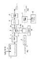
本実施形態では、TMP4とドライポンプ5の間に冷却トラップ機構6を配置している。この冷却トラップ機構6内には、ガス排気系配管3の途中のトラップ領域6aに配置した冷却トラップ7と、ガス排気系配管3から退避領域6bに退避した冷却トラップ8とが設けてあり、一方の冷却トラップ7が飽和状態になったときに、交換手段17により他方の冷却トラップ8と交換するようになっている。配管3から分離された冷却トラップは加熱再生手段18によってトラップされているガスを離脱させることにより再生される。以下、図1および冷却トラップ機構の具体的な構成を示した図2を参照して、さらに詳細に説明する。
【0022】
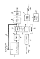
図2は、冷却トラップ7によって配管3を流れるガスをトラップし、これと並行して冷却トラップ8を再生している状況を示している。このとき、ゲートバルブ30aは閉状態、ゲートバルブ30bは開状態となっており、またゲートバルブ31aおよび31bはいずれも開状態となっている。
【0023】
冷却トラップ7および8にはガスとの接触面積を十分大きくするように冷却フィン7aおよび8aが設けてあり、図2の例では冷却フィン7aが冷凍機コンプレッサによって極低温まで冷却され、配管3を流れるガスをトラップする。
【0024】
例えば数十ロットの加工を行い冷却トラップにガスが大量に吸着されると冷却効率が低下し、また万が一冷却トラップの温度が上昇した場合にはガス圧力が上昇することになる。そのため、適当なタイミングで冷却トラップ7と冷却トラップ8とを交換し、冷却トラップの加熱再生(リジェネレーション)を行う。冷却トラップの交換は、図示しない上下移動機構によって冷却トラップ7および8を上下方向に移動させることで行う。冷却トラップの交換時期は、一定の運転時間毎に行ってもよいし、冷却トラップに吸着した吸着物の重量が一定以上になったときに行うようにしてもよい。
【0025】
冷却トラップの再生と並行してエッチングチャンバ内ではエッチングプロセスが行われており、配管3に配置された冷却トラップによって排出ガスのトラップが行われる。したがって、再生処理自体はエッチングプロセス時間を律速することはなく、また時間をかけて再生処理を行うことができる。
【0026】
再生動作は、ヒータ32aで冷却トラップ8を加熱してトラップされているガスを離脱させることによって行う。このときキャリアガス(パージガス)としてキャリアガス配管10から窒素ガスを供給するようにしてもよい。窒素圧力は図1に示したコンプレッサー9を使用して供給し、排ガス分離器11を最適な所定圧力に保つ。再生中の冷却トラップからは大量にガスが発生するため、その分圧が再生開始と同時に上昇する。冷却トラップから発生するガスの分圧と排ガス分離器11で必要な圧力の差をキャリアガスで補うことで、常に最適なガス分離条件を維持することができる。排ガス分離器で分離されたガスは、ガス回収用のシリンダー12に封入され、ガス工場へ送られてリサイクルされる。
【0027】
なお、冷却源或いはヒータからトラップ中或いは再生中の冷却トラップへの熱伝導を制御する機構を設け、温度調整を自在に行える機構を備えるようにしてもよい。このような機構を設けることにより、所望のガス種を選択的にトラップしたり(逆に言うと、所望のガス種を選択的にトラップを通過させる)、所望のガス種を選択的に離脱、回収させたりすることができる。
【0028】
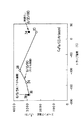
冷却トラップによるガス捕足の状況を調べるため、図3に示す装置を用い、四重極質量分析装置(QMS)14にトラップ機構6の前後(分析用ガスサンプリング配管15、16)からガスサンプリングを行い、ガス中の分子組成分析を行った。エッチングチャンバには、C4 F8 、CO、Arをそれぞれ20SCCM、300SCCM、380SCCM導入し、実際にフォトレジストをマスクとしたSiO2 膜をエッチングして排気されるガスについて調べた。その結果を図4に示す。
【0029】
検出された主なガスは、C4 F8 、C2 F6 、CF4 、SiF4 、COおよびArである。導入されたガスに対してトラップ前で検出されたガスの割合は、例えばC4 F8 ガスでは30−60%程度であり、これは40−70%のガスがエッチングや気相での反応によって消費されたことを意味している。また、SiF4 はエッチング生成物、C2 F6 、CF4 はガスの反応生成物と考えられ、それぞれ全ガスの数%存在する。一方、−180℃の冷却トラップを通過した後では、C4 F8 、C2 F6 、CF4 、SiF4 はすべて除去され、CO、Arといったさらに蒸気圧の高いガスだけが冷却トラップを通過してくることがわかる。
【0030】
なお、ここでは冷却トラップ温度−180℃の例だけしか示していないが、冷却トラップの温度を制御することにより、冷却トラップを通過するガスを選択することが可能となる。
【0031】
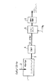
次に、本発明の第2の実施形態について、図5を参照して説明する。
本実施形態は、第1の実施形態と同様のシステムを備え、さらにそのシステムのガス排気配管3の冷却トラップ機構6の下流に分岐配管19を設けたものである。チャンバ1から排出されたガスは、図示していないバルブ、圧力調整機構、ガス混合機構を介し、分岐配管(循環ライン)19を通して一次ガス配管2と合流し、その一部のガスがエッチングチャンバ1に戻される。本システムでは、冷却トラップを通過してきたガスをそのまま破棄せずに有効に活用する、さらには、冷却トラップの温度調整により冷却トラップを通過するガス組成を制御して戻すことにより、プロセス性能の向上をはかるものである。その他の基本的な運用方法は図1等に示した第1の実施形態と同様である。
【0032】
本実施形態のシステムを使用したプロセスの評価結果について、その一部を図6に示す。
チャンバに導入するガスとしてC4 F8 /CO/Arを使用し、実効的な全ガス流量が6/30/180SCCMとなる条件で実験を行った。実験では、冷却トラップ温度に対するSiO2 膜のエッチング速度を求めた。サンプルとしてはレジストマスクを用い、0.6μm径のコンタクトホールのパターンを使用している。
【0033】
ガス循環の無い場合の室温でのエッチング速度を黒丸で示した。ここで50%だけガスを循環させる(もともと入れるガスをC4 F8 /CO/Ar=6/15/90SCCMとして、不足のCO/Ar=15/90SCCMを循環ラインから供給する)とエッチング速度は低下し、Siに対するエッチングの選択比も34から20へと低下する。これは、循環ラインを通じてエッチング生成物が戻り、エッチング反応を抑制するためである。
【0034】
これに対し、50%ガス循環の条件で、冷却トラップの温度を−180、−140、−100℃と変化させて特性を評価した。その結果、−180℃におけるエッチング特性は、常温で循環無し(黒丸)の場合とほぼ同等の結果であった。つまり、冷却トラップによりエッチング生成物がすべて除去されたため、循環無しと同等の性能が得られたと考えられる。
【0035】
ガスの循環の割合はさらに高めることも可能であり、例えばCOとArをほぼ100%循環させ、プラズマで分解されたCOの分だけ補充するような条件にすることも可能である。このようにほぼ100%循環させる場合は、特に排気系下流のドライポンプで排気すべきガス流量が激減するため、ドライポンプの小型化(大幅な省エネルギ、省スペース化が達成できる)、除害装置が小型化或いは不要となるなど、環境的な負荷を大幅に低減することができる。
【0036】
再び図6の実験結果に戻ると、冷却トラップ温度−140℃においては、エッチング速度が向上し、エッチング形状の観察においても、循環無しと比較して方向性良く、垂直に近いエッチング形状が達成された。
【0037】
このように、本実施形態のシステムを使用することで、PFCを完全に回収するとともに、実行的に使用するガス量を低減し、さらに、装置コスト低減やプロセス性能の向上といった多大な効果が得られる。
【0038】
次に、本発明の第3の実施形態について、図7を参照して説明する。
本実施形態は、図1の第1の実施形態と同様のプロセス装置20を複数設け、各プロセス装置毎に冷却トラップシステムを装備し、それぞれの冷却トラップからのガス回収を一台の排ガス分離器11で行うものである。
【0039】
それぞれのプロセス装置からのガス排出配管には、図示していないバルブと圧力計21aが接続され、再生されたガスの圧力を常時モニターする。一方、排ガス分離器11側にも圧力計21bが設置され、ここでの圧力がガス分離に最適となるように、各プロセス装置における加熱再生の温度、キャリアガスの圧力、流量等が制御される仕組みとなる。
【0040】
本実施形態では、冷却トラップと組み合わせて、オフラインでガス回収を行うことで、大規模なシステムを容易に構築することができる。また、メンブレンなどを用いたガス分離システムの性能を最も効率的に引き出し、工場全体としてのガス回収、環境保全システムに効果的に作用する。
【0041】
以上、本発明の実施形態について説明したが、本発明はこれらの実施形態に限定されるものではない。
上記実施形態では、エッチング装置を例に説明したが、冷却トラップとガス回収システムをオフラインで接続したシステムを構築するものであればよく、エッチング以外にも、CVD、表面改質、洗浄、不純物添加、それらのプロセスチャンバーのドライ洗浄などのガスを使用する半導体製造技術全般、さらにエキシマレーザの励起チャンバや電子ビーム描画装置の鏡筒内部のドライ洗浄など、直接のウエハプロセス以外にもガスを利用した技術にはすべて応用することが可能である。
その他、本発明はその趣旨を逸脱しない範囲内において種々変形して実施可能である。
【0042】
【発明の効果】
本発明によれば、冷却トラップを配管系の途中に配置したので、低コストで効率よくガスを回収することができる。また、ガスをトラップした冷却トラップを退避させて再生させ、代わりに再生された冷却トラップを配管系の途中に配置するので、効率よくガスのトラップおよび回収処理を行うことができる。さらに、冷却トラップを通過したガスを処理容器に再導入することにより、ガスの有効利用をはかることができる。
【図面の簡単な説明】
【図1】本発明の第1の実施形態について示した説明図。
【図2】本発明の第1の実施形態について、その主要部の構成を詳細に示した図。
【図3】本発明の第1の実施形態について、その作用を説明するための実験に用いる装置構成を示した図。
【図4】図3の装置を用いて行った実験結果について示した図。
【図5】本発明の第2の実施形態について示した説明図。
【図6】本発明の第2の実施形態によって得られる効果について示した図。
【図7】本発明の第3の実施形態について示した説明図。
【図8】従来技術について、その装置構成の一例を示した図。
【符号の説明】
1…エッチングチャンバ
2…ガス供給系配管
3…ガス排気系配管
4…ターボ分子ポンプ
5…ドライポンプ
6…冷却トラップ機構
7、8…冷却トラップ
9…コンプレッサー
10…キャリアガス配管
11…排ガス分離機
12…ガス回収シリンダー
13…除害装置
14…四重極質量分析器
15,16…分析用ガスサンプリング配管
17…交換手段
18…加熱再生手段
19…分岐配管
20…プロセス装置
21a、21b…圧力計
30a、30b、31a、31b…ゲートバルブ
32a…ヒータ[0001]
BACKGROUND OF THE INVENTION
The present invention can be applied to all processes using gas or processing on a substrate surface using gas (thin film formation, surface treatment, etching, surface modification, impurity addition, cleaning (impurity on the surface). And the like.
[0002]
[Prior art]
Processes using reactive gases are often used in semiconductor manufacturing techniques such as etching, CVD, surface modification, cleaning, and impurity addition. Many applications other than those used in direct wafer processing, such as dry cleaning of these process chambers, exciter laser excitation chambers, and dry cleaning of the inside of a lens barrel of an electron beam drawing apparatus, have been made.
[0003]
In these, in addition to highly reactive harmful gases, many stable gases called PFC (Per-Fluorocompounds) that are thought to affect global warming are also used. PFC has less production and emission than CO 2 , but its global warming potential is extremely high, so its relative influence is large, and it is necessary to eliminate its release into the atmosphere from the viewpoint of protecting the global environment. In addition, many harmful gases used in semiconductor manufacturing are also released into the atmosphere as they are, causing acid rain and environmental destruction. Recently, a detoxification system that removes exhausted gas by adsorbing to zeolite or activated carbon has come to be used, but the treatment of the adsorbent is incineration or landfill, and it still has a long-term impact on the environment. There is a big one.
[0004]
Various methods have been proposed for the recovery of PFC. For example, there is a system in which exhaust gas after passing through a detoxification device is once stored in a gas tank, transferred to a gas cylinder, transported to a gas purification factory, and purified and regenerated at the factory. Also, as an in-line recovery technology, a membrane with a fine hole at the molecular level is used, and the PFC is separated and selectively recovered using the difference in molecular size between dilution gases such as PFC and nitrogen. Has been proposed.
[0005]
However, the former technique needs to be operated as a large-scale gas recovery system and is not cost-effective except when a large amount of the same gas is used. As semiconductor devices advance, the gases used in the process change frequently. In fact, the types of gases used there are very wide.
[0006]
On the other hand, since the latter technique uses a membrane, there are many restrictions on the pressure of the gas supplied to the membrane and the concentration of the PFC gas with respect to the dilution gas, and a large amount of processing is performed while appropriately turning on and off the gas in each production apparatus. Since the supply of exhaust gas is extremely unstable in factories, it is not possible to operate such a system in an in-line method (collecting exhaust pipes of many devices and supplying them directly to the separation equipment on the spot) Almost impossible.
[0007]
FIG. 8 shows an example of the prior art, and is an explanatory view showing a schematic configuration and the like of an apparatus for processing a substrate to be processed using plasma.
In FIG. 8,
[0008]
A mixed gas in which the flow rate and mixing ratio of each gas are controlled is introduced into the
[0009]
The gas exhausted from the
[0010]
In the conventional recovery method, a gas filter is separated and recovered by providing a membrane filter and a cooling trap at the place where the scrubber before this final stage is exited, that is, the exhaust gas of many devices between factories. However, in such a system, the load on the recovery system always fluctuates due to a change in the operating status of the apparatus, so that the recovery efficiency is greatly reduced. Further, the exhaust system of each device, for example, a dry pump, is supplied with a large amount of nitrogen for purging to dilute harmful reactive gas, thereby suppressing corrosion and deterioration of the pump. Therefore, the CF gas concentration in the gas supplied to the recovery system is diluted to less than 0.2%, and the recovery efficiency is further reduced.
[0011]
[Problems to be solved by the invention]
As described above, in the conventional apparatus or method, it is difficult to efficiently recover the PFC gas discharged from the chamber or the like at a low cost.
The present invention has been made to solve the above-described conventional problems, and an object of the present invention is to provide an apparatus and a method capable of efficiently collecting gas discharged from a container such as a chamber at a low cost. .
[0012]
[Means for Solving the Problems]
A gas process apparatus according to the present invention includes a processing container into which a gas used for a predetermined process is introduced, a piping system for discharging the gas from the processing container, a cooling trap disposed in the middle of the piping system, An exchange means for exchanging the cooling trap withdrawn from the piping system, a regeneration means for releasing the gas trapped in the cooling trap withdrawn from the piping system from the cooling trap and regenerating the cooling trap, and And a recovery means for recovering the gas separated from the cooling trap by the regeneration means.
[0013]
According to the present invention, since the cooling trap is arranged in the middle of the piping system, for example, the PFC gas can be trapped at a stage where the PFC gas or the like is not diluted so much, and the PFC gas or the like can be efficiently recovered at low cost Can do. Further, while the cooling trap trapped with PFC gas or the like is retracted and regenerated, the regenerated cooling trap is disposed in the middle of the piping system instead, so that the gas trap and recovery process can be performed efficiently.
[0014]
Moreover, in this invention, you may make it provide further the means to reintroduce the gas which passed the cooling trap provided in the middle of the piping system to a processing container.
In this way, by re-introducing gas by providing means for reintroduction, it is possible not only to remove harmful gases, but also to recycle gases, greatly reducing the environmental burden associated with gas production and abatement processes. (To remove harmful gases by adsorbing them in adsorbents such as zeolite, it is necessary to treat the used adsorbents. With a heavy environmental burden.)
[0015]
In the present invention, a temperature control means for controlling the gas species adsorbed on the cooling trap or the gas species separated from the cooling trap by controlling the temperature of the cooling trap may be further provided.
[0016]
Further, in the present invention, a plurality of apparatuses composed of the processing vessel, the piping system, the exchange means, and the regeneration means are provided, and the gas separated from each cooling trap by each regeneration means is intensively recovered by the recovery means. Also good.
[0017]
In the gas process apparatus according to the present invention, the process of trapping the gas flowing in the piping system by the cooling trap disposed in the middle of the piping system, and the gas trapped in the cooling trap retreated from the piping system by the regeneration means It is preferable to perform the separation process in parallel.
[0018]
In this way, by performing the trap process and the regeneration process in parallel, one of the cooling traps traps the gas (that is, the predetermined process is performed in the processing container), while the other Since the cooling trap can be regenerated, the predetermined processing can be performed without substantially reducing the total processing time.
[0019]
DETAILED DESCRIPTION OF THE INVENTION
Hereinafter, embodiments of the present invention will be described with reference to the drawings.
First, a first embodiment of the present invention will be described with reference to FIG.
In this embodiment, the present invention is applied to an apparatus for processing a substrate to be processed using plasma, and corresponds to the conventional example of FIG.
[0020]
The
[0021]
In the present embodiment, a
[0022]
FIG. 2 shows a situation in which the gas flowing through the
[0023]
The cooling traps 7 and 8 are provided with cooling fins 7a and 8a so that the contact area with the gas is sufficiently large. In the example of FIG. 2, the cooling fins 7a are cooled to a very low temperature by a refrigerator compressor, Trap the flowing gas.
[0024]
For example, if a large amount of gas is adsorbed on the cooling trap after processing several tens of lots, the cooling efficiency is lowered, and if the temperature of the cooling trap rises, the gas pressure increases. Therefore, the
[0025]
In parallel with the regeneration of the cooling trap, an etching process is performed in the etching chamber, and the exhaust gas is trapped by the cooling trap disposed in the
[0026]
The regeneration operation is performed by heating the
[0027]
Note that a mechanism for controlling heat conduction from the cooling source or the heater to the cooling trap being trapped or being regenerated may be provided, and a mechanism for freely adjusting the temperature may be provided. By providing such a mechanism, the desired gas species can be selectively trapped (in other words, the desired gas species can be selectively passed through the trap), or the desired gas species can be selectively released. Can be recovered.
[0028]
In order to investigate the state of gas trapping by the cold trap, gas sampling is performed from the front and back of the trap mechanism 6 (analysis
[0029]
The main gases detected are C 4 F 8 , C 2 F 6 , CF 4 , SiF 4 , CO and Ar. The ratio of the gas detected before the trap with respect to the introduced gas is, for example, about 30-60% for C 4 F 8 gas, which is 40-70% due to etching or reaction in the gas phase. It means that it has been consumed. SiF 4 is considered to be an etching product, and C 2 F 6 and CF 4 are considered to be gas reaction products, each of which is present in several percent of the total gas. On the other hand, after passing through the −180 ° C. cooling trap, C 4 F 8 , C 2 F 6 , CF 4 and SiF 4 are all removed, and only gases with higher vapor pressure such as CO and Ar pass through the cooling trap. You can see that
[0030]
Although only the example of the cooling trap temperature of −180 ° C. is shown here, the gas passing through the cooling trap can be selected by controlling the temperature of the cooling trap.
[0031]
Next, a second embodiment of the present invention will be described with reference to FIG.
This embodiment includes a system similar to that of the first embodiment, and further includes a
[0032]
A part of the evaluation results of the process using the system of this embodiment is shown in FIG.
The experiment was performed under the condition that C 4 F 8 / CO / Ar was used as the gas to be introduced into the chamber and the effective total gas flow rate was 6/30/180 SCCM. In the experiment, the etching rate of the SiO 2 film with respect to the cooling trap temperature was obtained. A resist mask is used as a sample, and a contact hole pattern having a diameter of 0.6 μm is used.
[0033]
The etching rate at room temperature in the absence of gas circulation is indicated by black circles. Here, 50% of the gas is circulated (the gas to be originally supplied is C 4 F 8 / CO / Ar = 6/15/90 SCCM, and insufficient CO / Ar = 15/90 SCCM is supplied from the circulation line). The etching selectivity to Si also decreases from 34 to 20. This is because the etching product returns through the circulation line and suppresses the etching reaction.
[0034]
On the other hand, the characteristics were evaluated by changing the temperature of the cooling trap to −180, −140, and −100 ° C. under the condition of 50% gas circulation. As a result, the etching characteristics at −180 ° C. were almost the same as the case of no circulation (black circle) at room temperature. That is, it is considered that the performance equivalent to that without circulation is obtained because all the etching products are removed by the cooling trap.
[0035]
The rate of gas circulation can be further increased. For example, CO and Ar can be circulated almost 100%, and the conditions can be such that CO is decomposed by plasma. When circulating almost 100% in this way, the flow rate of gas to be exhausted by the dry pump, especially downstream of the exhaust system, is drastically reduced, so the dry pump can be downsized (significant energy and space savings can be achieved) and eliminated. It is possible to greatly reduce the environmental load such as downsizing or unnecessary equipment.
[0036]
Returning to the experimental results in FIG. 6 again, the etching rate is improved at the cooling trap temperature of −140 ° C., and even in the observation of the etching shape, an etching shape close to the vertical is achieved with better direction than that without circulation. It was.
[0037]
As described above, by using the system of the present embodiment, the PFC is completely recovered, the amount of gas used in practice is reduced, and a great effect such as reduction in apparatus cost and improvement in process performance is obtained. It is done.
[0038]
Next, a third embodiment of the present invention will be described with reference to FIG.
In this embodiment, a plurality of
[0039]
A valve (not shown) and a pressure gauge 21a are connected to the gas discharge pipe from each process apparatus, and the pressure of the regenerated gas is constantly monitored. On the other hand, a pressure gauge 21b is also installed on the exhaust gas separator 11 side, and the heating regeneration temperature, carrier gas pressure, flow rate, etc. in each process apparatus are controlled so that the pressure here is optimal for gas separation. It becomes a mechanism.
[0040]
In the present embodiment, a large-scale system can be easily constructed by performing gas recovery offline in combination with a cooling trap. Moreover, the performance of a gas separation system using a membrane or the like is most efficiently extracted, and it effectively acts on a gas recovery and environmental protection system as a whole factory.
[0041]
As mentioned above, although embodiment of this invention was described, this invention is not limited to these embodiment.
In the above embodiment, the etching apparatus has been described as an example. However, it is sufficient to construct a system in which a cooling trap and a gas recovery system are connected offline. Besides etching, CVD, surface modification, cleaning, impurity addition In addition to semiconductor manufacturing technologies that use gases such as dry cleaning of those process chambers, and gas cleaning in addition to direct wafer processes such as excimer laser excitation chambers and dry cleaning inside electron beam lithography system barrels All technologies can be applied.
In addition, the present invention can be variously modified and implemented without departing from the spirit of the present invention.
[0042]
【The invention's effect】
According to the present invention, since the cooling trap is disposed in the middle of the piping system, the gas can be efficiently recovered at a low cost. Further, since the cooled trap where the gas is trapped is retracted and regenerated, and the regenerated cooled trap is disposed in the middle of the piping system, the gas trap and recovery process can be performed efficiently. Furthermore, the gas can be effectively used by reintroducing the gas that has passed through the cooling trap into the processing container.
[Brief description of the drawings]
FIG. 1 is an explanatory diagram showing a first embodiment of the present invention.
FIG. 2 is a diagram showing in detail the configuration of the main part of the first embodiment of the present invention.
FIG. 3 is a diagram showing an apparatus configuration used for an experiment for explaining the operation of the first embodiment of the present invention.
4 is a diagram showing the results of an experiment conducted using the apparatus of FIG.
FIG. 5 is an explanatory diagram showing a second embodiment of the present invention.
FIG. 6 is a diagram showing effects obtained by the second embodiment of the present invention.
FIG. 7 is an explanatory diagram showing a third embodiment of the present invention.
FIG. 8 is a diagram showing an example of a device configuration of a conventional technique.
[Explanation of symbols]
DESCRIPTION OF
Claims (8)
前記処理容器内で前記被処理基板を保持するサセプタと、
前記処理容器内に処理ガスを供給するガス供給手段と、
前記処理容器に接続され前記処理容器からのフロロカーボンガスを含んだ排気ガスを流す排気ラインと、前記排気ラインに配置され前記処理容器内を排気する排気ポンプとを有するガス排気手段と、
前記排気ガス中のフロロカーボンガスを冷却吸着によってトラップすることが可能であるとともに、吸着されたフロロカーボンガスを加熱によって離脱させることが可能なトラップと、
前記トラップが前記排気ラインから離隔された状態で、前記吸着されたフロロカーボンガスを前記トラップから離脱させるための再生ラインと、
前記トラップから離脱したフロロカーボンガスを回収するために前記再生ラインに接続された回収手段と、
前記トラップが前記排気ラインに位置するトラップモードと前記トラップが前記再生ラインに位置する再生モードとを切り換えるものであって、前記トラップモードにあるトラップを前記処理容器と前記排気ポンプとの間に位置させる切り換え手段と、
前記トラップモードにあるトラップを冷却する冷却手段と、
前記再生モードにあるトラップを加熱する加熱手段と、
を備えた半導体処理システムであって、
前記冷却手段は、前記トラップモードにあるトラップを、前記フロロカーボンガスが冷却吸着によって前記トラップに吸着され且つ前記フロロカーボンガスよりも高い蒸気圧を有するその他のガスが前記トラップを通過するような温度に冷却するものであることを特徴とする半導体処理システム。A processing container for storing a substrate to be processed;
A susceptor for holding the substrate to be processed in the processing container;
Gas supply means for supplying a processing gas into the processing container;
A gas exhaust means having an exhaust line for flowing an exhaust gas containing a fluorocarbon gas from the processing container and connected to the processing container; and an exhaust pump disposed in the exhaust line for exhausting the inside of the processing container;
A trap capable of trapping the fluorocarbon gas in the exhaust gas by cooling adsorption, and capable of releasing the adsorbed fluorocarbon gas by heating,
A regeneration line for separating the adsorbed fluorocarbon gas from the trap in a state where the trap is separated from the exhaust line;
Recovery means connected to the regeneration line to recover the fluorocarbon gas detached from the trap;
The trap is switched between a trap mode in which the trap is positioned in the exhaust line and a regeneration mode in which the trap is positioned in the regeneration line, and the trap in the trap mode is positioned between the processing vessel and the exhaust pump. Switching means for causing
Cooling means for cooling the trap in the trap mode;
Heating means for heating the trap in the regeneration mode;
A semiconductor processing system comprising:
The cooling means cools the trap in the trap mode to a temperature at which the fluorocarbon gas is adsorbed to the trap by cooling adsorption and another gas having a vapor pressure higher than that of the fluorocarbon gas passes through the trap. A semiconductor processing system characterized by that.
前記処理容器内で前記被処理基板を保持するサセプタと、
前記処理容器内に処理ガスを供給するガス供給手段と、
前記処理容器に接続され前記処理容器からのフロロカーボンガスを含んだ排気ガスを流す排気ラインと、前記排気ラインに配置され前記処理容器内を排気する排気ポンプとを有するガス排気手段と、
前記排気ガス中のフロロカーボンガスを冷却吸着によってトラップすることが可能であるとともに、吸着されたフロロカーボンガスを加熱によって離脱させることが可能な二つのトラップと、
前記トラップが前記排気ラインから離隔された状態で、前記吸着されたフロロカーボンガスを前記トラップから離脱させるための再生ラインと、
前記トラップから離脱したフロロカーボンガスを回収するために前記再生ラインに接続された回収手段と、
前記トラップの一方が前記排気ラインに位置するトラップモードであり且つ前記トラップの他方が前記再生ラインに位置する再生モードである状態と、前記トラップの一方が再生モードであり且つ前記トラップの他方がトラップモードである状態とを交互に切り換えるものであって、前記トラップモードにあるトラップを前記処理容器と前記排気ポンプとの間に位置させる切り換え手段と、
前記トラップモードにあるトラップを冷却する冷却手段と、
前記再生モードにあるトラップを加熱する加熱手段と、
を備えた半導体処理システムであって、
前記冷却手段は、前記トラップモードにあるトラップを、前記フロロカーボンガスが冷却吸着によって前記トラップモードにあるトラップに吸着され且つ前記フロロカーボンガスよりも高い蒸気圧を有するその他のガスが前記トラップモードにあるトラップを通過するような温度に冷却するものであることを特徴とする半導体処理システム。A processing container for storing a substrate to be processed;
A susceptor for holding the substrate to be processed in the processing container;
Gas supply means for supplying a processing gas into the processing container;
A gas exhaust means having an exhaust line for flowing an exhaust gas containing a fluorocarbon gas from the processing container and connected to the processing container; and an exhaust pump disposed in the exhaust line for exhausting the inside of the processing container;
Two traps capable of trapping fluorocarbon gas in the exhaust gas by cooling adsorption and capable of separating the adsorbed fluorocarbon gas by heating;
A regeneration line for separating the adsorbed fluorocarbon gas from the trap in a state where the trap is separated from the exhaust line;
Recovery means connected to the regeneration line to recover the fluorocarbon gas detached from the trap;
A state in which one of the traps is in a trap mode located in the exhaust line and the other in the regeneration mode is in a regeneration mode located in the regeneration line; and one of the traps is in a regeneration mode and the other in the trap is a trap A switching means for alternately switching between the state of the mode and the trap in the trap mode between the processing vessel and the exhaust pump;
Cooling means for cooling the trap in the trap mode;
Heating means for heating the trap in the regeneration mode;
A semiconductor processing system comprising:
The cooling means is configured to trap the trap in the trap mode. The trap in which the fluorocarbon gas is adsorbed by the trap in the trap mode by cooling adsorption and the other gas having a higher vapor pressure than the fluorocarbon gas is in the trap mode. A semiconductor processing system, wherein the semiconductor processing system is cooled to a temperature that passes through the substrate.
前記排気ガス中のフロロカーボンガスを前記トラップの一方でトラップする第1のトラップ工程と、
前記トラップの他方に吸着されたフロロカーボンガスを離脱させることにより、前記第1のトラップ工程と並行して前記トラップの他方を再生する第1の再生工程と、
前記排気ガス中のフロロカーボンガスを前記トラップの他方でトラップする第2のトラップ工程と、
前記トラップの一方に吸着されたフロロカーボンガスを離脱させることにより、前記第2のトラップ工程と並行して前記トラップの一方を再生する第2の再生工程と、を備え、
前記第1のトラップ工程及び第1の再生工程と、前記第2のトラップ工程及び第2の再生工程とを交互に行うことを特徴とする半導体処理システムの使用方法。 A method of using the semiconductor processing system of claim 2 ,
A first trap step of trapping the fluorocarbon gas in the exhaust gas with one of the traps;
A first regeneration step of regenerating the other of the traps in parallel with the first trapping step by releasing the fluorocarbon gas adsorbed on the other of the traps;
A second trap step of trapping the fluorocarbon gas in the exhaust gas with the other of the traps;
A second regeneration step of regenerating one of the traps in parallel with the second trap step by releasing the fluorocarbon gas adsorbed on one of the traps;
A method of using a semiconductor processing system, wherein the first trapping step and the first regeneration step, and the second trapping step and the second regeneration step are alternately performed.
Priority Applications (2)
| Application Number | Priority Date | Filing Date | Title |
|---|---|---|---|
| JP01966498A JP3643474B2 (en) | 1998-01-30 | 1998-01-30 | Semiconductor processing system and method of using semiconductor processing system |
| US09/239,793 US6334928B1 (en) | 1998-01-30 | 1999-01-29 | Semiconductor processing system and method of using the same |
Applications Claiming Priority (1)
| Application Number | Priority Date | Filing Date | Title |
|---|---|---|---|
| JP01966498A JP3643474B2 (en) | 1998-01-30 | 1998-01-30 | Semiconductor processing system and method of using semiconductor processing system |
Publications (2)
| Publication Number | Publication Date |
|---|---|
| JPH11219936A JPH11219936A (en) | 1999-08-10 |
| JP3643474B2 true JP3643474B2 (en) | 2005-04-27 |
Family
ID=12005519
Family Applications (1)
| Application Number | Title | Priority Date | Filing Date |
|---|---|---|---|
| JP01966498A Expired - Fee Related JP3643474B2 (en) | 1998-01-30 | 1998-01-30 | Semiconductor processing system and method of using semiconductor processing system |
Country Status (2)
| Country | Link |
|---|---|
| US (1) | US6334928B1 (en) |
| JP (1) | JP3643474B2 (en) |
Families Citing this family (51)
| Publication number | Priority date | Publication date | Assignee | Title |
|---|---|---|---|---|
| US6849471B2 (en) | 2003-03-28 | 2005-02-01 | Reflectivity, Inc. | Barrier layers for microelectromechanical systems |
| EP1052466A4 (en) * | 1998-10-29 | 2002-09-18 | Ebara Corp | Pfc type gas recovery method and device |
| US6391385B1 (en) * | 1999-10-18 | 2002-05-21 | Advanced Technology Materials, Inc. | Method of abating of effluents from chemical vapor deposition processes using organometallic source reagents |
| US7041224B2 (en) * | 1999-10-26 | 2006-05-09 | Reflectivity, Inc. | Method for vapor phase etching of silicon |
| US6949202B1 (en) * | 1999-10-26 | 2005-09-27 | Reflectivity, Inc | Apparatus and method for flow of process gas in an ultra-clean environment |
| US6773687B1 (en) * | 1999-11-24 | 2004-08-10 | Tokyo Electron Limited | Exhaust apparatus for process apparatus and method of removing impurity gas |
| JP2001252527A (en) * | 2000-03-13 | 2001-09-18 | Seiko Epson Corp | Method and apparatus for treating pfc |
| US6863019B2 (en) * | 2000-06-13 | 2005-03-08 | Applied Materials, Inc. | Semiconductor device fabrication chamber cleaning method and apparatus with recirculation of cleaning gas |
| JP4046474B2 (en) | 2000-11-13 | 2008-02-13 | 株式会社荏原製作所 | Continuous processing trap device and method of operating the trap device |
| US7189332B2 (en) | 2001-09-17 | 2007-03-13 | Texas Instruments Incorporated | Apparatus and method for detecting an endpoint in a vapor phase etch |
| US6965468B2 (en) | 2003-07-03 | 2005-11-15 | Reflectivity, Inc | Micromirror array having reduced gap between adjacent micromirrors of the micromirror array |
| US6955707B2 (en) * | 2002-06-10 | 2005-10-18 | The Boc Group, Inc. | Method of recycling fluorine using an adsorption purification process |
| US6821347B2 (en) * | 2002-07-08 | 2004-11-23 | Micron Technology, Inc. | Apparatus and method for depositing materials onto microelectronic workpieces |
| US6955725B2 (en) * | 2002-08-15 | 2005-10-18 | Micron Technology, Inc. | Reactors with isolated gas connectors and methods for depositing materials onto micro-device workpieces |
| JP4113755B2 (en) * | 2002-10-03 | 2008-07-09 | 東京エレクトロン株式会社 | Processing equipment |
| US6926775B2 (en) * | 2003-02-11 | 2005-08-09 | Micron Technology, Inc. | Reactors with isolated gas connectors and methods for depositing materials onto micro-device workpieces |
| US20040185661A1 (en) * | 2003-03-17 | 2004-09-23 | Sherer John Michael | Scrubber system for pretreatment of an effluent waste stream containing arsenic |
| US7335396B2 (en) * | 2003-04-24 | 2008-02-26 | Micron Technology, Inc. | Methods for controlling mass flow rates and pressures in passageways coupled to reaction chambers and systems for depositing material onto microfeature workpieces in reaction chambers |
| US7235138B2 (en) * | 2003-08-21 | 2007-06-26 | Micron Technology, Inc. | Microfeature workpiece processing apparatus and methods for batch deposition of materials on microfeature workpieces |
| US7344755B2 (en) * | 2003-08-21 | 2008-03-18 | Micron Technology, Inc. | Methods and apparatus for processing microfeature workpieces; methods for conditioning ALD reaction chambers |
| US7422635B2 (en) * | 2003-08-28 | 2008-09-09 | Micron Technology, Inc. | Methods and apparatus for processing microfeature workpieces, e.g., for depositing materials on microfeature workpieces |
| US7645704B2 (en) * | 2003-09-17 | 2010-01-12 | Texas Instruments Incorporated | Methods and apparatus of etch process control in fabrications of microstructures |
| US7056806B2 (en) * | 2003-09-17 | 2006-06-06 | Micron Technology, Inc. | Microfeature workpiece processing apparatus and methods for controlling deposition of materials on microfeature workpieces |
| US7581511B2 (en) * | 2003-10-10 | 2009-09-01 | Micron Technology, Inc. | Apparatus and methods for manufacturing microfeatures on workpieces using plasma vapor processes |
| US7647886B2 (en) * | 2003-10-15 | 2010-01-19 | Micron Technology, Inc. | Systems for depositing material onto workpieces in reaction chambers and methods for removing byproducts from reaction chambers |
| US7258892B2 (en) * | 2003-12-10 | 2007-08-21 | Micron Technology, Inc. | Methods and systems for controlling temperature during microfeature workpiece processing, e.g., CVD deposition |
| US20080241587A1 (en) * | 2004-03-29 | 2008-10-02 | Tadahiro Ohmi | Film-Forming Apparatus And Film-Forming Method |
| US20050249873A1 (en) * | 2004-05-05 | 2005-11-10 | Demetrius Sarigiannis | Apparatuses and methods for producing chemically reactive vapors used in manufacturing microelectronic devices |
| US8133554B2 (en) * | 2004-05-06 | 2012-03-13 | Micron Technology, Inc. | Methods for depositing material onto microfeature workpieces in reaction chambers and systems for depositing materials onto microfeature workpieces |
| US7699932B2 (en) * | 2004-06-02 | 2010-04-20 | Micron Technology, Inc. | Reactors, systems and methods for depositing thin films onto microfeature workpieces |
| DE102006038309A1 (en) * | 2006-08-15 | 2008-02-21 | Extrude Hone Gmbh | Device for the thermal deburring of workpieces |
| KR100809852B1 (en) * | 2007-05-17 | 2008-03-04 | (주)엘오티베큠 | Intergrated apparatus for vacuum producing |
| US8318131B2 (en) | 2008-01-07 | 2012-11-27 | Mcalister Technologies, Llc | Chemical processes and reactors for efficiently producing hydrogen fuels and structural materials, and associated systems and methods |
| US9188086B2 (en) * | 2008-01-07 | 2015-11-17 | Mcalister Technologies, Llc | Coupled thermochemical reactors and engines, and associated systems and methods |
| US8441361B2 (en) | 2010-02-13 | 2013-05-14 | Mcallister Technologies, Llc | Methods and apparatuses for detection of properties of fluid conveyance systems |
| US20110203776A1 (en) * | 2009-02-17 | 2011-08-25 | Mcalister Technologies, Llc | Thermal transfer device and associated systems and methods |
| US8318269B2 (en) * | 2009-02-17 | 2012-11-27 | Mcalister Technologies, Llc | Induction for thermochemical processes, and associated systems and methods |
| CN102844106B (en) * | 2010-02-13 | 2015-02-04 | 麦卡利斯特技术有限责任公司 | Chemical reactors with re-radiating surfaces and associated systems and methods |
| KR20130036001A (en) * | 2010-02-13 | 2013-04-09 | 맥알리스터 테크놀로지즈 엘엘씨 | Reactor vessel with transmissive surfaces for producing hydrogen-based fuels and structural elements, and associated systems and methods |
| JP2012082462A (en) * | 2010-10-08 | 2012-04-26 | Toshiba Corp | Ion implantation apparatus and method |
| US8911703B2 (en) | 2011-08-12 | 2014-12-16 | Mcalister Technologies, Llc | Reducing and/or harvesting drag energy from transport vehicles, including for chemical reactors, and associated systems and methods |
| US8671870B2 (en) | 2011-08-12 | 2014-03-18 | Mcalister Technologies, Llc | Systems and methods for extracting and processing gases from submerged sources |
| US8734546B2 (en) | 2011-08-12 | 2014-05-27 | Mcalister Technologies, Llc | Geothermal energization of a non-combustion chemical reactor and associated systems and methods |
| WO2013025659A1 (en) | 2011-08-12 | 2013-02-21 | Mcalister Technologies, Llc | Reducing and/or harvesting drag energy from transport vehicles, includings for chemical reactors, and associated systems and methods |
| US8821602B2 (en) | 2011-08-12 | 2014-09-02 | Mcalister Technologies, Llc | Systems and methods for providing supplemental aqueous thermal energy |
| WO2013025650A1 (en) | 2011-08-12 | 2013-02-21 | Mcalister Technologies, Llc | Mobile transport platforms for producing hydrogen and structural materials and associated systems and methods |
| WO2014160301A1 (en) | 2013-03-14 | 2014-10-02 | Mcalister Technologies, Llc | Method and apparatus for generating hydrogen from metal |
| US10153141B2 (en) * | 2014-02-14 | 2018-12-11 | Electronics And Telecommunications Research Institute | Apparatus for monitoring gas and plasma process equipment including the same |
| KR102185404B1 (en) * | 2018-05-31 | 2020-12-01 | 대전대학교 산학협력단 | Semiconductor Device Manufacturing System with recoverable Fluorocarbon-based Precursor |
| KR102273855B1 (en) * | 2019-03-22 | 2021-07-07 | 대전대학교 산학협력단 | The gas recovery apparatus for semiconductor process |
| WO2021061904A1 (en) * | 2019-09-24 | 2021-04-01 | University Of Georgia Research Foundation, Inc. | Collection and separation systems and methods of use thereof and isotope analysis systems and methods of use thereof |
Family Cites Families (6)
| Publication number | Priority date | Publication date | Assignee | Title |
|---|---|---|---|---|
| US4593530A (en) * | 1984-04-10 | 1986-06-10 | Air Products And Chemicals, Inc. | Method and apparatus for improving the sensitivity of a leak detector utilizing a cryopump |
| US5169407A (en) * | 1987-03-31 | 1992-12-08 | Kabushiki Kaisha Toshiba | Method of determining end of cleaning of semiconductor manufacturing apparatus |
| US4957523A (en) * | 1989-01-27 | 1990-09-18 | Pacific Consolidated Industries | High speed pressure swing adsorption liquid oxygen/liquid nitrogen generating plant |
| GB9011535D0 (en) | 1990-05-23 | 1990-07-11 | Oxford Lasers Ltd | Gas management system |
| US5363369A (en) * | 1993-03-31 | 1994-11-08 | At&T Bell Laboratories | System for inter packet community communication |
| US5622682A (en) * | 1994-04-06 | 1997-04-22 | Atmi Ecosys Corporation | Method for concentration and recovery of halocarbons from effluent gas streams |
-
1998
- 1998-01-30 JP JP01966498A patent/JP3643474B2/en not_active Expired - Fee Related
-
1999
- 1999-01-29 US US09/239,793 patent/US6334928B1/en not_active Expired - Fee Related
Also Published As
| Publication number | Publication date |
|---|---|
| US6334928B1 (en) | 2002-01-01 |
| JPH11219936A (en) | 1999-08-10 |
Similar Documents
| Publication | Publication Date | Title |
|---|---|---|
| JP3643474B2 (en) | Semiconductor processing system and method of using semiconductor processing system | |
| US10920315B2 (en) | Plasma foreline thermal reactor system | |
| US20010015133A1 (en) | Gas recovery system and gas recovery method | |
| US8632687B2 (en) | Method for electron beam induced etching of layers contaminated with gallium | |
| JP2012517581A (en) | Exhaust gas treatment method | |
| JP2010212293A (en) | Substrate processing apparatus, method of reproducing filter material and storage medium | |
| JP2007105657A (en) | Gas treatment apparatus | |
| US6051053A (en) | Trapping device and method of operation therefor | |
| US20060231119A1 (en) | Apparatus and method for cleaning a substrate | |
| KR20100105493A (en) | Substrate processing apparatus and exhaust method therefor | |
| JP2019195758A (en) | Gas separator and gas separation method | |
| KR100743275B1 (en) | Plasma processing method and post-processing method | |
| US7767006B2 (en) | Ozone processing apparatus and ozone processing method | |
| JP4549563B2 (en) | Halogen-containing gas treatment equipment | |
| JP2002273169A5 (en) | ||
| JPH02307527A (en) | Solvent adsorbing material and solvent recovery apparatus | |
| JP2005142377A (en) | Recycle system for cleaning gas | |
| KR20100023363A (en) | A method for cleaning parts of semiconductor equipment and an apparatus for cleaning parts of semiconductor equipment using the same | |
| JP5258739B2 (en) | Halogen-containing gas treatment equipment | |
| GB2588908A (en) | Inert gas recovery from a semiconductor manufacturing tool | |
| US20230111710A1 (en) | Purification processing apparatus, substrate processing system, and processing method | |
| JP4127586B2 (en) | Semiconductor device manufacturing method and semiconductor manufacturing apparatus | |
| JPH0653171A (en) | Plasma apparatus | |
| JP3015744B2 (en) | Continuous processing equipment | |
| JP2737613B2 (en) | Method of forming fine pattern |
Legal Events
| Date | Code | Title | Description |
|---|---|---|---|
| A521 | Written amendment |
Free format text: JAPANESE INTERMEDIATE CODE: A523 Effective date: 20040408 |
|
| A621 | Written request for application examination |
Free format text: JAPANESE INTERMEDIATE CODE: A621 Effective date: 20040408 |
|
| A977 | Report on retrieval |
Free format text: JAPANESE INTERMEDIATE CODE: A971007 Effective date: 20040915 |
|
| A131 | Notification of reasons for refusal |
Free format text: JAPANESE INTERMEDIATE CODE: A131 Effective date: 20041012 |
|
| A521 | Written amendment |
Free format text: JAPANESE INTERMEDIATE CODE: A523 Effective date: 20041203 |
|
| TRDD | Decision of grant or rejection written | ||
| A01 | Written decision to grant a patent or to grant a registration (utility model) |
Free format text: JAPANESE INTERMEDIATE CODE: A01 Effective date: 20050125 |
|
| A61 | First payment of annual fees (during grant procedure) |
Free format text: JAPANESE INTERMEDIATE CODE: A61 Effective date: 20050128 |
|
| FPAY | Renewal fee payment (event date is renewal date of database) |
Free format text: PAYMENT UNTIL: 20080204 Year of fee payment: 3 |
|
| FPAY | Renewal fee payment (event date is renewal date of database) |
Free format text: PAYMENT UNTIL: 20090204 Year of fee payment: 4 |
|
| FPAY | Renewal fee payment (event date is renewal date of database) |
Free format text: PAYMENT UNTIL: 20100204 Year of fee payment: 5 |
|
| LAPS | Cancellation because of no payment of annual fees |