JP3639552B2 - Damping structure for ramen frame - Google Patents
Damping structure for ramen frame Download PDFInfo
- Publication number
- JP3639552B2 JP3639552B2 JP2001323046A JP2001323046A JP3639552B2 JP 3639552 B2 JP3639552 B2 JP 3639552B2 JP 2001323046 A JP2001323046 A JP 2001323046A JP 2001323046 A JP2001323046 A JP 2001323046A JP 3639552 B2 JP3639552 B2 JP 3639552B2
- Authority
- JP
- Japan
- Prior art keywords
- damping structure
- rigid frame
- column
- reinforcing member
- reinforcing material
- Prior art date
- Legal status (The legal status is an assumption and is not a legal conclusion. Google has not performed a legal analysis and makes no representation as to the accuracy of the status listed.)
- Expired - Lifetime
Links
Images


Landscapes
- Building Environments (AREA)
- Joining Of Building Structures In Genera (AREA)
Description
【0001】
【発明の属する技術分野】
本発明は、鉄骨製柱と梁を備えたラーメン架構のための制振構造に関する。
【0002】
【従来の技術】
アンボンドブレースをはじめ、ブレース、間柱、壁タイプの制振部材が数多く開発されている。これらはバランスを考え配置しなければならないため、平面計画上支障を及ぼすことも少なくない。また将来の模様替え等の自由度を制約することも考えられる。
【0003】
そのような平面計画上の理由から純ラーメン架構が多く採用されているが、純ラーメン架構での制振工法であればこれらの制約を受けることなく構造計画が可能となり、意匠・構造の両者にとって計画上のメリットが得られる。
【0004】
特開平10−37301号公報により、梁よりも降伏点の小さな材料からなるエネルギー吸収部材を梁端部に接合・分離可能に接合することが知られている。この場合、低降伏点のエネルギー吸収部材を正しく機能させるには、エネルギー吸収部材の降伏点を、梁の降伏点よりもかなり低く設定する必要があり、その結果エネルギー吸収が少なく、制震効果が少ないという欠点がある。更に、このエネルギー吸収部材は梁と柱の間の隅部に三角形状に形成配置されているので、柱または梁から出張るため、邪魔になる。
【0005】
【発明が解決しようとする課題】
そこで、本発明の課題は、低降伏点の補強材を用いることなく、梁の補強が可能である、ラーメン架構用制振構造を提供することである。
【0006】
【課題を解決するための手段および発明の効果】
この課題は、柱の近くの梁部分に板状の梁と同一の降伏点を有する補強材を備え、この補強材の一端が柱に固定連結され、他端が柱から離れたところで梁に固定連結されていることと、補強材の両端の間の中間範囲が梁の長手方向において梁によって拘束されないで、梁の水平方向および上下方向において拘束されていることと、補強材が梁の長手方向における所定以上の梁の変形を防止することによって解決される。
【0007】
地震時に梁に曲げ応力が生じると、先ず最初に柱寄りの梁の端部分が降伏してエネルギー吸収を行う。このとき、補強材の中間範囲は梁の長手方向において梁によって拘束されていないので、ほとんど変形しない。よって、補強材はそれ以上の梁の変形を防止し、建物の過大な変形を抑止する。
【0008】
補強材の両端の間の中間範囲を梁の長手方向で拘束されないようにかつ梁の長手方向に対して横方向および垂直方向で拘束されるように梁に保持するために、補強材または梁に多数の長手方向ルーズホールが形成され、このルーズホールに座屈補剛ボルトが挿入されていると有利である。
【0009】
更に、梁がH形鋼であり、補強材がこのH形鋼のフランジの側面または内側に取付けられていると、補強材が梁から出張らず、邪魔になることがない。
【0010】
更に、補強材の端部は溶接によってまたはボルトによって梁または柱に固定連結可能である。
【0011】
【発明の実施の形態】
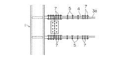
次に、図を参照して本発明の実施の形態を詳しく説明する。図1,2,3は、本発明によるラーメン架構の制振構造の第1の実施の形態を示している。ラーメン架構は柱1と、この柱1に例えばシェアプレート2によって連結された鉄骨製の梁3とからなっている。梁3はH形鋼からなり、水平な2つのフランジ3aと、このフランジの間に位置する垂直なウェブプレート3bとを有する。柱1の近くにおいて梁3は、上下のフランジ3aの外側に板状の補強材4を備えている。この補強材4は一端4aが柱1に溶接され、他端4bが柱1から離れたところで梁3のフランジ3aに溶接されている。
【0012】
補強材4は両端4a,4bの間の中間範囲において、中ボルトからなる多数の座屈補剛ボルト5によって梁3のフランジ3aに保持されている。この座屈補剛ボルト5は補強材4に形成されたルーズホール6と、フランジ3aに形成された図示していない穴に挿通され、ナットで止められている。フランジ3aに接触する補強材4の面は滑らかに形成され、小さな摩擦係数を有する。補強材4の中間範囲は座屈補剛ボルト5によって梁の長手方向に対して横方向(水平方向)および垂直方向(上下方向)では拘束されるがしかし、ルーズホール6と補強材4の滑らかな面により、梁の長手方向では拘束されない。
【0013】
補強材4とフランジ3aの間の摩擦係数を更に小さくするために、フランジ3a側の補強材4の面を、その一部だけがフランジ3aに接触するように形成することができる。これは例えばフランジ3a側の補強材4の面に窪みを形成することによって行われる。更に、補強材の面を滑らかに形成する代わりに、アンボンド材をフランジ3aと補強材4の中間範囲の間に配置してもよい。
【0014】
例えば地震時に梁3に曲げ応力が生じると、先ず最初に柱寄りの梁3の端部分が降伏してエネルギー吸収を行う。このとき、補強材4の中間範囲は梁の長手方向において梁3によって拘束されていないので、ほとんど変形しない。よって、補強材はそれ以上の梁の変形を防止し、建物の過大な変形を抑止する。
【0015】
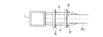
図4,5,6は、本発明によるラーメン架構の制振構造の第2の実施の形態を示している。この実施の形態は、補強材4の端部が溶接されないで、高力ボルト7によって梁3に剛接されている点が前述の第1の実施の形態と異なっている。そのほかは第1の実施の形態と同じである。
【0016】
図7,8,9は、本発明によるラーメン架構の制振構造の第3の実施の形態を示している。この実施の形態では、補強材4が梁3のフランジ3aの側面に取付けられ、座屈補剛ボルトの代わりに座屈補剛用ガセットまたは座屈補剛用アングルが設けられている。
【0017】
図10,11,12は、本発明によるラーメン架構の制振構造の第4の実施の形態を示している。この実施の形態では、補強材4が梁3のフランジ3aの内面に取付けられ、座屈補剛ボルトの代わりに座屈補剛用ガセットまたは座屈補剛用アングルが設けられている。
【図面の簡単な説明】
【図1】 本発明の第1の実施の形態によるラーメン架構用制振構造の正面図である。
【図2】 図1のラーメン架構用制振構造の右側面図である。
【図3】 図1のラーメン架構用制振構造の平面図である。
【図4】 本発明の第2の実施の形態によるラーメン架構用制振構造の正面図である。
【図5】 図4のラーメン架構用制振構造の右側面図である。
【図6】 図4のラーメン架構用制振構造の平面図である。
【図7】 本発明の第3の実施の形態によるラーメン架構用制振構造の正面図である。
【図8】 図7のラーメン架構用制振構造の右側面図である。
【図9】 図7のラーメン架構用制振構造の平面図である。
【図10】 本発明の第4の実施の形態によるラーメン架構用制振構造の正面図である。
【図11】 図10のラーメン架構用制振構造の右側面図である。
【図12】 図10のラーメン架構用制振構造の平面図である。
【符号の説明】
1 柱
2 シェアプレート
3 梁
3a フランジ
3b ウェブプレート
4 補強材
4a,4b 補強材の端部
5 座屈補剛ボルト
6 ルーズホール
7 高力ボルト
8 座屈補剛用ガセット
9 座屈補剛用アングル[0001]
BACKGROUND OF THE INVENTION
The present invention relates to a vibration damping structure for a rigid frame having steel columns and beams.
[0002]
[Prior art]
Many undamped braces, braces, studs and wall-type damping members have been developed. Since these must be arranged in consideration of balance, there are many cases in which the plan planning is hindered. In addition, it may be possible to restrict the degree of freedom for future redesign.
[0003]
Pure ramen frames are often used for such reasons for floorplanning, but the vibration control method using pure ramen frames enables structural planning without these limitations, and it is useful for both design and structure. Benefit from planning.
[0004]
Japanese Patent Application Laid-Open No. 10-37301 discloses that an energy absorbing member made of a material having a yield point smaller than that of a beam is bonded to the beam end portion so as to be bonded / separable. In this case, in order for an energy absorbing member with a low yield point to function correctly, it is necessary to set the yield point of the energy absorbing member to be considerably lower than the yield point of the beam. There is a disadvantage that there are few. Further, since the energy absorbing member is formed and arranged in a triangular shape at the corner between the beam and the column, the energy absorbing member makes a business trip from the column or the beam, which is obstructive.
[0005]
[Problems to be solved by the invention]
Then, the subject of this invention is providing the damping structure for frame structures which can reinforce a beam, without using the reinforcement material of a low yield point.
[0006]
[Means for Solving the Problems and Effects of the Invention]
The task is to provide a reinforcing material with the same yield point as the plate-like beam in the beam part near the column, one end of this reinforcing material is fixedly connected to the column, and the other end is fixed to the beam at a distance from the column. and that it is connected, at an intermediate range between the ends of the reinforcing member is not constrained by the beam in the longitudinal direction of the beam, and that it is constrained in the horizontal direction and the vertical direction of the beam, longitudinal reinforcement beams This is solved by preventing the deformation of the beam beyond a predetermined value .
[0007]
When the bending stress on the beam during an earthquake occurs, carry out the energy-absorbing first to surrender beamed end portion of the pillar closer to first. At this time, since the intermediate range of the reinforcing material is not restrained by the beam in the longitudinal direction of the beam, it hardly deforms. Therefore, the reinforcing material prevents further deformation of the beam and suppresses excessive deformation of the building.
[0008]
In order to hold the intermediate range between the ends of the stiffener to the beam so that it is not constrained in the longitudinal direction of the beam and constrained in the direction transverse and perpendicular to the longitudinal direction of the beam It is advantageous if a number of longitudinal loose holes are formed, into which buckling stiffening bolts are inserted.
[0009]
Furthermore, if the beam is H-shaped steel and the reinforcing material is attached to the side surface or inside of the flange of the H-shaped steel, the reinforcing material does not travel from the beam and does not get in the way.
[0010]
Furthermore, the end of the stiffener can be fixedly connected to the beam or column by welding or by bolts.
[0011]
DETAILED DESCRIPTION OF THE INVENTION
Next, embodiments of the present invention will be described in detail with reference to the drawings. 1, 2 and 3 show a first embodiment of a damping structure for a rigid frame structure according to the present invention. The frame frame includes a column 1 and a
[0012]
The reinforcing
[0013]
In order to further reduce the coefficient of friction between the reinforcing
[0014]
For example, when bending stress to the
[0015]
4, 5 and 6 show a second embodiment of the damping structure for a rigid frame structure according to the present invention. This embodiment is different from the first embodiment described above in that the end of the reinforcing
[0016]
7, 8 and 9 show a third embodiment of the damping structure for a rigid frame structure according to the present invention. In this embodiment, the reinforcing
[0017]
10, 11 and 12 show a fourth embodiment of the damping structure for a rigid frame structure according to the present invention. In this embodiment, the reinforcing
[Brief description of the drawings]
FIG. 1 is a front view of a vibration damping structure for a rigid frame structure according to a first embodiment of the present invention.
2 is a right side view of the vibration suppression structure for the rigid frame structure of FIG. 1. FIG.
3 is a plan view of the damping structure for the rigid frame structure of FIG. 1. FIG.
FIG. 4 is a front view of a damping structure for a rigid frame structure according to a second embodiment of the present invention.
5 is a right side view of the vibration damping structure for the rigid frame structure of FIG. 4. FIG.
6 is a plan view of the vibration damping structure for the rigid frame structure of FIG. 4. FIG.
FIG. 7 is a front view of a vibration suppression structure for a rigid frame structure according to a third embodiment of the present invention.
8 is a right side view of the damping structure for the rigid frame structure of FIG.
9 is a plan view of the vibration damping structure for the rigid frame structure of FIG. 7;
FIG. 10 is a front view of a vibration suppression structure for a rigid frame structure according to a fourth embodiment of the present invention.
11 is a right side view of the vibration suppression structure for the rigid frame structure of FIG. 10;
12 is a plan view of the vibration damping structure for the rigid frame structure of FIG. 10;
[Explanation of symbols]
DESCRIPTION OF SYMBOLS 1
Claims (4)
Priority Applications (1)
| Application Number | Priority Date | Filing Date | Title |
|---|---|---|---|
| JP2001323046A JP3639552B2 (en) | 2001-10-22 | 2001-10-22 | Damping structure for ramen frame |
Applications Claiming Priority (1)
| Application Number | Priority Date | Filing Date | Title |
|---|---|---|---|
| JP2001323046A JP3639552B2 (en) | 2001-10-22 | 2001-10-22 | Damping structure for ramen frame |
Publications (2)
| Publication Number | Publication Date |
|---|---|
| JP2003129565A JP2003129565A (en) | 2003-05-08 |
| JP3639552B2 true JP3639552B2 (en) | 2005-04-20 |
Family
ID=19139995
Family Applications (1)
| Application Number | Title | Priority Date | Filing Date |
|---|---|---|---|
| JP2001323046A Expired - Lifetime JP3639552B2 (en) | 2001-10-22 | 2001-10-22 | Damping structure for ramen frame |
Country Status (1)
| Country | Link |
|---|---|
| JP (1) | JP3639552B2 (en) |
Cited By (2)
| Publication number | Priority date | Publication date | Assignee | Title |
|---|---|---|---|---|
| CN103556780A (en) * | 2013-10-29 | 2014-02-05 | 刘阳 | Flange buckling-preventing section steel and concrete composite beam |
| CN109610666A (en) * | 2018-12-13 | 2019-04-12 | 大连理工大学 | A dual energy dissipation mechanism system |
Families Citing this family (2)
| Publication number | Priority date | Publication date | Assignee | Title |
|---|---|---|---|---|
| JP6304074B2 (en) * | 2015-03-03 | 2018-04-04 | Jfeスチール株式会社 | Method and structure for welding and joining steel members |
| KR101868677B1 (en) * | 2016-01-29 | 2018-06-18 | 최상은 | Connection unit for coupling main steel girder and ancillary steel girder and, connection methods using the same |
Family Cites Families (3)
| Publication number | Priority date | Publication date | Assignee | Title |
|---|---|---|---|---|
| JP2669740B2 (en) * | 1991-12-04 | 1997-10-29 | 株式会社フジタ | Damping frame structure |
| JP3882325B2 (en) * | 1998-03-24 | 2007-02-14 | 株式会社大林組 | Friction damper |
| JP3842484B2 (en) * | 1999-05-19 | 2006-11-08 | 積水ハウス株式会社 | Column and beam joint structure and building having the same |
-
2001
- 2001-10-22 JP JP2001323046A patent/JP3639552B2/en not_active Expired - Lifetime
Cited By (3)
| Publication number | Priority date | Publication date | Assignee | Title |
|---|---|---|---|---|
| CN103556780A (en) * | 2013-10-29 | 2014-02-05 | 刘阳 | Flange buckling-preventing section steel and concrete composite beam |
| CN103556780B (en) * | 2013-10-29 | 2016-05-18 | 华侨大学 | The anti-buckling shape steel-concrete combined beam in a kind of edge of a wing |
| CN109610666A (en) * | 2018-12-13 | 2019-04-12 | 大连理工大学 | A dual energy dissipation mechanism system |
Also Published As
| Publication number | Publication date |
|---|---|
| JP2003129565A (en) | 2003-05-08 |
Similar Documents
| Publication | Publication Date | Title |
|---|---|---|
| KR101263078B1 (en) | Connection metal fitting and building with the same | |
| US5349794A (en) | Wall for damping vibration | |
| JP6990979B2 (en) | Framing structure of a building | |
| JP2007277952A (en) | Seismic joint structure and construction method thereof | |
| JP3639552B2 (en) | Damping structure for ramen frame | |
| JP7228344B2 (en) | Joint structure of reinforced concrete frame and brace and precast member | |
| JP2020041319A (en) | Joint structure of main structure and brace | |
| JP2020076208A (en) | Reinforcing structure for column and beam frame | |
| JP2018104995A (en) | Building structure and reinforcement method of existing column beam frame | |
| JP4971701B2 (en) | Damping structure and damping panel | |
| JPH05331964A (en) | Reinforcing structure for opening of steel beam | |
| JPH11152929A (en) | Seismic strengthening method for steel building. | |
| JP4049120B2 (en) | Building seismic control structure | |
| JP5057570B2 (en) | Bonding structure of viscous walls | |
| JPH08246547A (en) | Pole-beam junction structure | |
| JP4305230B2 (en) | Column and beam joint structure | |
| JP2005042423A (en) | Shear reinforcement structure of metal plate | |
| JP6240420B2 (en) | Seismic reinforcement structure | |
| JP6979283B2 (en) | Steel column beam frame of steel pipe column and H-shaped steel beam | |
| JP4678098B2 (en) | Vibration control pillar | |
| JP4758683B2 (en) | Reinforcement structure of unit building | |
| JP6645770B2 (en) | Seismic reinforcement structure | |
| JP7097589B1 (en) | Reinforcing panel mounting structure | |
| JP3842587B2 (en) | Reinforcing method and reinforcing structure of reinforced concrete ramen structure | |
| JP3225454B2 (en) | Building structure |
Legal Events
| Date | Code | Title | Description |
|---|---|---|---|
| A02 | Decision of refusal |
Free format text: JAPANESE INTERMEDIATE CODE: A02 Effective date: 20040608 |
|
| A521 | Written amendment |
Free format text: JAPANESE INTERMEDIATE CODE: A523 Effective date: 20040809 |
|
| A911 | Transfer to examiner for re-examination before appeal (zenchi) |
Free format text: JAPANESE INTERMEDIATE CODE: A911 Effective date: 20041102 |
|
| TRDD | Decision of grant or rejection written | ||
| A01 | Written decision to grant a patent or to grant a registration (utility model) |
Free format text: JAPANESE INTERMEDIATE CODE: A01 Effective date: 20041214 |
|
| A61 | First payment of annual fees (during grant procedure) |
Free format text: JAPANESE INTERMEDIATE CODE: A61 Effective date: 20050114 |
|
| R150 | Certificate of patent or registration of utility model |
Free format text: JAPANESE INTERMEDIATE CODE: R150 Ref document number: 3639552 Country of ref document: JP Free format text: JAPANESE INTERMEDIATE CODE: R150 |
|
| FPAY | Renewal fee payment (event date is renewal date of database) |
Free format text: PAYMENT UNTIL: 20080121 Year of fee payment: 3 |
|
| FPAY | Renewal fee payment (event date is renewal date of database) |
Free format text: PAYMENT UNTIL: 20090121 Year of fee payment: 4 |
|
| R250 | Receipt of annual fees |
Free format text: JAPANESE INTERMEDIATE CODE: R250 |
|
| FPAY | Renewal fee payment (event date is renewal date of database) |
Free format text: PAYMENT UNTIL: 20100121 Year of fee payment: 5 |
|
| R250 | Receipt of annual fees |
Free format text: JAPANESE INTERMEDIATE CODE: R250 |
|
| FPAY | Renewal fee payment (event date is renewal date of database) |
Free format text: PAYMENT UNTIL: 20110121 Year of fee payment: 6 |
|
| R250 | Receipt of annual fees |
Free format text: JAPANESE INTERMEDIATE CODE: R250 |
|
| FPAY | Renewal fee payment (event date is renewal date of database) |
Free format text: PAYMENT UNTIL: 20120121 Year of fee payment: 7 |
|
| R250 | Receipt of annual fees |
Free format text: JAPANESE INTERMEDIATE CODE: R250 |
|
| FPAY | Renewal fee payment (event date is renewal date of database) |
Free format text: PAYMENT UNTIL: 20120121 Year of fee payment: 7 |
|
| FPAY | Renewal fee payment (event date is renewal date of database) |
Free format text: PAYMENT UNTIL: 20130121 Year of fee payment: 8 |
|
| R250 | Receipt of annual fees |
Free format text: JAPANESE INTERMEDIATE CODE: R250 |
|
| FPAY | Renewal fee payment (event date is renewal date of database) |
Free format text: PAYMENT UNTIL: 20130121 Year of fee payment: 8 |
|
| FPAY | Renewal fee payment (event date is renewal date of database) |
Free format text: PAYMENT UNTIL: 20140121 Year of fee payment: 9 |
|
| R250 | Receipt of annual fees |
Free format text: JAPANESE INTERMEDIATE CODE: R250 |
|
| R250 | Receipt of annual fees |
Free format text: JAPANESE INTERMEDIATE CODE: R250 |
|
| R250 | Receipt of annual fees |
Free format text: JAPANESE INTERMEDIATE CODE: R250 |
|
| R250 | Receipt of annual fees |
Free format text: JAPANESE INTERMEDIATE CODE: R250 |
|
| R250 | Receipt of annual fees |
Free format text: JAPANESE INTERMEDIATE CODE: R250 |
|
| R250 | Receipt of annual fees |
Free format text: JAPANESE INTERMEDIATE CODE: R250 |
|
| R250 | Receipt of annual fees |
Free format text: JAPANESE INTERMEDIATE CODE: R250 |
|
| R250 | Receipt of annual fees |
Free format text: JAPANESE INTERMEDIATE CODE: R250 |
|
| R250 | Receipt of annual fees |
Free format text: JAPANESE INTERMEDIATE CODE: R250 |
|
| EXPY | Cancellation because of completion of term |