JP3638605B2 - High efficiency and high speed control unit for chain shifter - Google Patents
High efficiency and high speed control unit for chain shifter Download PDFInfo
- Publication number
- JP3638605B2 JP3638605B2 JP51184195A JP51184195A JP3638605B2 JP 3638605 B2 JP3638605 B2 JP 3638605B2 JP 51184195 A JP51184195 A JP 51184195A JP 51184195 A JP51184195 A JP 51184195A JP 3638605 B2 JP3638605 B2 JP 3638605B2
- Authority
- JP
- Japan
- Prior art keywords
- latch
- cam
- eccentric
- trip
- upshift
- Prior art date
- Legal status (The legal status is an assumption and is not a legal conclusion. Google has not performed a legal analysis and makes no representation as to the accuracy of the status listed.)
- Expired - Fee Related
Links
Images


Classifications
-
- B—PERFORMING OPERATIONS; TRANSPORTING
- B62—LAND VEHICLES FOR TRAVELLING OTHERWISE THAN ON RAILS
- B62M—RIDER PROPULSION OF WHEELED VEHICLES OR SLEDGES; POWERED PROPULSION OF SLEDGES OR SINGLE-TRACK CYCLES; TRANSMISSIONS SPECIALLY ADAPTED FOR SUCH VEHICLES
- B62M9/00—Transmissions characterised by use of an endless chain, belt, or the like
- B62M9/04—Transmissions characterised by use of an endless chain, belt, or the like of changeable ratio
- B62M9/06—Transmissions characterised by use of an endless chain, belt, or the like of changeable ratio using a single chain, belt, or the like
- B62M9/10—Transmissions characterised by use of an endless chain, belt, or the like of changeable ratio using a single chain, belt, or the like involving different-sized wheels, e.g. rear sprocket chain wheels selectively engaged by the chain, belt, or the like
- B62M9/12—Transmissions characterised by use of an endless chain, belt, or the like of changeable ratio using a single chain, belt, or the like involving different-sized wheels, e.g. rear sprocket chain wheels selectively engaged by the chain, belt, or the like the chain, belt, or the like being laterally shiftable, e.g. using a rear derailleur
- B62M9/131—Front derailleurs
- B62M9/132—Front derailleurs electrically or fluid actuated; Controls thereof
-
- B—PERFORMING OPERATIONS; TRANSPORTING
- B62—LAND VEHICLES FOR TRAVELLING OTHERWISE THAN ON RAILS
- B62M—RIDER PROPULSION OF WHEELED VEHICLES OR SLEDGES; POWERED PROPULSION OF SLEDGES OR SINGLE-TRACK CYCLES; TRANSMISSIONS SPECIALLY ADAPTED FOR SUCH VEHICLES
- B62M25/00—Actuators for gearing speed-change mechanisms specially adapted for cycles
- B62M25/08—Actuators for gearing speed-change mechanisms specially adapted for cycles with electrical or fluid transmitting systems
-
- B—PERFORMING OPERATIONS; TRANSPORTING
- B62—LAND VEHICLES FOR TRAVELLING OTHERWISE THAN ON RAILS
- B62M—RIDER PROPULSION OF WHEELED VEHICLES OR SLEDGES; POWERED PROPULSION OF SLEDGES OR SINGLE-TRACK CYCLES; TRANSMISSIONS SPECIALLY ADAPTED FOR SUCH VEHICLES
- B62M9/00—Transmissions characterised by use of an endless chain, belt, or the like
- B62M9/04—Transmissions characterised by use of an endless chain, belt, or the like of changeable ratio
- B62M9/06—Transmissions characterised by use of an endless chain, belt, or the like of changeable ratio using a single chain, belt, or the like
- B62M9/10—Transmissions characterised by use of an endless chain, belt, or the like of changeable ratio using a single chain, belt, or the like involving different-sized wheels, e.g. rear sprocket chain wheels selectively engaged by the chain, belt, or the like
- B62M9/12—Transmissions characterised by use of an endless chain, belt, or the like of changeable ratio using a single chain, belt, or the like involving different-sized wheels, e.g. rear sprocket chain wheels selectively engaged by the chain, belt, or the like the chain, belt, or the like being laterally shiftable, e.g. using a rear derailleur
- B62M9/121—Rear derailleurs
- B62M9/122—Rear derailleurs electrically or fluid actuated; Controls thereof
-
- B—PERFORMING OPERATIONS; TRANSPORTING
- B62—LAND VEHICLES FOR TRAVELLING OTHERWISE THAN ON RAILS
- B62M—RIDER PROPULSION OF WHEELED VEHICLES OR SLEDGES; POWERED PROPULSION OF SLEDGES OR SINGLE-TRACK CYCLES; TRANSMISSIONS SPECIALLY ADAPTED FOR SUCH VEHICLES
- B62M9/00—Transmissions characterised by use of an endless chain, belt, or the like
- B62M9/04—Transmissions characterised by use of an endless chain, belt, or the like of changeable ratio
- B62M9/06—Transmissions characterised by use of an endless chain, belt, or the like of changeable ratio using a single chain, belt, or the like
- B62M9/10—Transmissions characterised by use of an endless chain, belt, or the like of changeable ratio using a single chain, belt, or the like involving different-sized wheels, e.g. rear sprocket chain wheels selectively engaged by the chain, belt, or the like
- B62M9/12—Transmissions characterised by use of an endless chain, belt, or the like of changeable ratio using a single chain, belt, or the like involving different-sized wheels, e.g. rear sprocket chain wheels selectively engaged by the chain, belt, or the like the chain, belt, or the like being laterally shiftable, e.g. using a rear derailleur
- B62M9/131—Front derailleurs
- B62M9/133—Front derailleurs changing gears automatically
-
- F—MECHANICAL ENGINEERING; LIGHTING; HEATING; WEAPONS; BLASTING
- F16—ENGINEERING ELEMENTS AND UNITS; GENERAL MEASURES FOR PRODUCING AND MAINTAINING EFFECTIVE FUNCTIONING OF MACHINES OR INSTALLATIONS; THERMAL INSULATION IN GENERAL
- F16H—GEARING
- F16H63/00—Control outputs from the control unit to change-speed- or reversing-gearings for conveying rotary motion or to other devices than the final output mechanism
- F16H63/02—Final output mechanisms therefor; Actuating means for the final output mechanisms
- F16H63/30—Constructional features of the final output mechanisms
- F16H63/304—Constructional features of the final output mechanisms the final output mechanisms comprising elements moved by electrical or magnetic force
Description
技術分野
本発明は、チェーン駆動装置の入/出力駆動比を切り換えるべく、チェーン駆動装置のチェーンをシフトする(切換える)技術に関し、より詳しくは、自転車等のチェーンの効率的な高速シフト技術に関する。
発明の背景
米国特許第4,127,038号には、変速中に確実な駆動連結を維持しながら、異なる直径をもつスプロケットからスプロケットへとチェーンが移動される構成のスプロケットシフト組立体が開示されている。チェーンは、該チェーンが係合しているプロケット(「チェーン係合スプロケット」と呼ぶ)から受入れスプロケットへとシフトされ、このシフトは、受入れスプロケットの歯とチェーン係合スプロケットの歯とが整合するように、受入れスプロケットのセクタを枢動させることにより行なわれる。チェーンが受入れスプロケットにシフトされた後、セクタは、チェーンが該セクタと係合した状態でその元の位置に戻される。
米国特許第4,580,997号には、2段変速スプロケット/チェーンシフト組立体が開示されている。一方のスプロケットは、枢着された小形スプロケットセグメントを有している。シフト機構は、スプロケットセグメントを枢動して該セグメントとチェーンとを整合させることにより、一方のスプロケットと係合しているチェーンを他方のスプロケットにシフトする。この特許はまた、爪ハウジング及び枢動カムを使用して、スプロケット/チェーン組立体のシフト時及び非シフト時に必要とされる、スプロケットにより支持された爪の移動方向の決定を行なうことを開示している。
米国特許第4,894,046号には、爪ハウジング内でカム組立体を位置決めするための、可逆回転電気セレクタモータを使用したチェーンシフタ用制御ユニットが開示されている。これにより、移動爪は、チェーンシフトに必要とされる方向決めがなされる。ばね付勢形ラッチキーがカムセレクタを位置決めする。ばねは、左右のラッチアームがカムセレクタを中心位置に保持するように、これらのラッチアームを引き離す方向に押圧する。作動に際し、モータは、2つのラッチアームのうちの一方のラッチアームをラッチキーから離れる方向に押して、カムセレクタが回転できるようにしなければならない。ばねはキーに対してラッチ部材を押しつける。従ってモータは、ばねの力に打ち勝つ大きい力を発生して、ラッチキーを移動させなくてはならない。モータが必要とする力は、モータを駆動するバッテリに大きな要求をする。従って、バッテリを頻繁に取り替えなくてはならない。或いは、より大容量のバッテリが必要になるけれども、大きく且つ重いバッテリは自転車に使用するには適していない。
また、モータから力は瞬時に出力されるものではなく、一定時間を要する。上記装置のモータは、該モータがラッチアームを移動させるのに充分な大きさの力を発生するまで、一方のラッチアームを一定時間押さえていなくてはならない。これはバッテリに対する別の要求を賦課するだけでなく、モータの付勢とチェーンのシフトとの間の時間遅延は好ましくない。
従って、出力効率の高いチェーンシフタ用の改善された制御ユニットが要望されている。また、カムセレクタの迅速位置決めが可能なチェーンシフタ用の改善された制御ユニットが要望されている。
発明の要約
本発明は、ばね付勢されたカム組立体を作動させるのに充分な力を得るため、不釣り合い偏心体を加速することにより発生される衝撃力を部分的に使用することにより、従来技術の上記及び他の問題を解決する。
本発明の制御ユニットは、偏心組立体に連結された可逆回転電気セレクタモータを有している。偏心組立体は、モータに取り付けられた偏心駆動体と、該偏心駆動体に対して摺動可能に取り付けられたハンマすなわち偏心体とを有している。偏心体はスロット状孔の回りで摺動できる。偏心体は、偏心駆動体と軸線方向に整合するように、ばねにより押圧されている。
モータが回転し始めると、偏心駆動体及び偏心体も同様に回転し、加速し始める。偏心体はこれが回転するときに不釣り合い状態になり、偏心駆動体との軸線方向整合を解く半径方向外方の力を発生する。偏心組立体が加速し続けると、偏心組立体は、偏心体の質量の加速により発生する力がばね力に打ち勝ち且つこれにより偏心体がスロット状孔に沿って偏心駆動体との軸線方向整合を解く方向に摺動する位置に到達する。偏心体が偏心駆動体と軸線方向に整合しない場合には、偏心体はラッチトリップと衝突する。
ラッチトリップは左右1対の枢動ラッチアームの間に配置される。ばねがラッチアームの一部を互いに引き離すように押圧し、キーは、両ラッチアーム間に配置され且つラッチトリップが中央に位置するときにラッチアーム及びばねにより保持される。偏心体がラッチトリップと衝突すると、ラッチトリップは衝撃力を一方のラッチアームに伝達し、該アームをキーから離れる方向に移動させる。他方のラッチアームは、ばねを介してキーを回転させる。スピンドルは、キーの回転運動をカムセレクタに伝達して、チェーンのシフトができるようにする。
本発明の重要な点は、小さな質量をもつ部材すなわち偏心体を回転させ且つ加速することにある。良く知られているように、力は、質量と加速度との積に等しい。質量が最小に維持されるならば、この質量を加速させるのに必要な力は小さくて済む。モータは、迅速に且つモータに過度のエネルギ条件を賦課することなく、本発明の小質量偏心体を回転させ且つ加速することができる。偏心体の質量は充分な力を発生させるべく加速され、該偏心体が衝突するときにこの力をラッチトリップに伝達し、ラッチトリップはラッチアームをキーから離れる方向に押すのに充分な力を有する。偏心体により発生される力は、該偏心体から、両ラッチアームの間に位置するラッチトリップを介して、実質的に同時に一方のラッチアームに伝達される。
本発明の他の特徴及び関連する長所は、下記の図面と共に好ましい実施例に関する下記の詳細な説明を読むことにより明らかになるであろう。
【図面の簡単な説明】
第1図は、本発明のチェーンシフタ用制御ユニットが設けられた自転車を示す斜視図である。
第2図は、本発明の制御ユニットが自転車フレームの一部に取り付けられた状態を示す拡大側面図である。
第3図は、制御ユニットの側面図である。
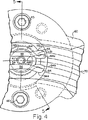
第4図は、拡大端面図である。
第5図は、第4図の5−5線に沿う拡大断面図である。
第6図は、第5図の6−6線に沿う断面図である。
第7図は、制御ユニットの分解図である。
第8A図は、本発明の偏心駆動体を示す平面図である。
第8B図は、第8A図の偏心駆動体を示す底面図である。
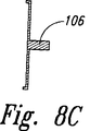
第8C図は、第8A図の8C−8C線に沿う本発明の偏心駆動体の断面図である。
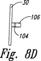
第8D図は、第8A図の偏心駆動体の左側面図である。
第8E図は、第8A図の偏心駆動体の正面図である。
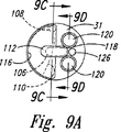
第9A図は、本発明の偏心体の平面図である。
第9B図は、第9A図の偏心体の底面図である。
第9C図は、第9A図の偏心体の9C−9C線に沿う断面図である。
第9D図は、第9A図の偏心体の9D−9D線に沿う断面図である。
第9E図は、第9A図の偏心体の右側面図である。
第9F図は、第9A図の偏心体の正面図である。
第9G図は、本発明のばねの平面図である。
第9H図は、本発明の偏心ウェイト122の斜視図である。
第10A図は、本発明のラッチトリップ32の平面図である。
第10B図は、第10A図のラッチトリップの平面図である。
第10C図は、第10A図の10C−10C線に沿うラッチトリップの断面図である。
第10D図は、第10A図の10D−10D線に沿うラッチトリップの断面図である。
第10E図は、第10A図のラッチトリップの右側面図である。
第10F図は、第10A図のラッチトリップの正面図である。
第11図は、本発明のピンプレートの平面図である。
本発明の好ましい実施例の詳細な説明
第1図は、全体を参照番号11で示す自転車に取り付けられた制御ユニット10を示す。図示のように、自転車11は、通常のフレーム12、前輪13、ハンドルバー14、一方のハンドルグリップ14aに隣接したブレーキレバー15、後輪16、ペダルクランク17、後輪に取り付けられた後スプロケット18、チェーン18a、チェーン緊張器19、及び、クランクに取り付けられたスプロケット組立体20を有している。スプロケット組立体20は、枢動形スプロケットセグメントと、スプロケットセグメントの枢動及びスプロケット組立体と係合するチェーンのシフトを行なうべく異なる移動経路を通る方向に指向される爪とを備えた、米国特許第4,580,997号に開示された形式が好ましい。
他方のハンドグリップ14bに隣接するハンドルバー14に隣接して、制御スイッチ21が取り付けられており、該制御スイッチ21は「アップ」ボタン22及び「ダウン」ボタン23を有している。第2図及び第7図に示すように、電線24が、スイッチ21から保護シース(鞘)25の中を可逆回転電気モータ26(第7図)へと延びている。モータ26は、該モータに電力を供給するバッテリ(図示せず)を収容する容器として機能するハウジング27内に入れ子状に挿入される。本発明の高い効率により、従来技術の装置に必要とされるバッテリよりも小形のバッテリを使用できる。
モータ26の出力軸28は偏心駆動体30のボア29内に延びている。偏心駆動体30は、ハンマすなわち偏心体31及びラッチトリップ32と協働する。偏心駆動体30、偏心体31及びラッチトリップ32については、第8A図〜第8E図、第9A図〜第9H図及び第10A図〜第10F図に関連してより詳細に説明する。
ラッチトリップ32の一方の面から延びているラッチトリップ部材142の両側に1対のラッチアーム33、33′がそれぞれ配置されている。各ラッチアームの面からピン35が延びており、両ラッチアームの間には、ばね36が嵌合されている。ばね36の両端部にピン35が挿入され、これにより、両ラッチアームの対向する端部を互いに引き離す方向に押圧する。
ばね36は、両ラッチアーム33、33′を引き離す方向に押圧し、ピン39上で枢動させ且つキー45に押しつける。キー45は両ラッチアーム間に配置され、且つラッチトリップ部材142が両ラッチアーム間の中央に位置決めされると、ラッチアーム及びばねにより保持される。ラッチトリップ部材が回転させられると、一方のラッチアームがキーから移動させられ、ばね及び他方のラッチアームによってキーが回転される。
各ラッチアームはピン39の一端に枢着され、ピンの他端はブシュ39a内に挿入されている。ブシュ39aはブシュ40のボア40aの中を延びている。ピンプレート34は、ピン39の一端を受け入れて、両ラッチアーム33、33′をブシュ40内に保持している。
ブシュ40のボア42内にはスピンドル41が入れ子状に挿入され、該スピンドルから延びているシャフト43がキー45のボア44内に入れ子状に挿入される。キー調節板46の孔47aを通ってキー45の孔47及びシャフト43の孔48内に挿入されるロックねじ46aが、シャフトに対してキーをロックする。ロックユニットが組み立てられたとき、キー45は両ラッチアーム33、33′の間に配置される。
キー45、ラッチアーム33、33′はプラスチックのような耐久性のある弾性材料、好ましくは商品名DELRINというプラスチックで作られているのが好ましい。キー調整板46は、キー45の凹状部分に当接する凸状面を有しているのが好ましい。
ロックねじ46aが締めつけられると、キー調節板46の凸状面は、キー45の凹状部分を外方に押しやり、両ラッチアーム33、33′と接触させる。
第4図及び第5図に示すように、スピンドル41のカラー52から延びているフランジ51には、溝50が形成されている。米国特許第4,580,997号に開示された形式が好ましいカムセレクタ54は上下のカム面55、56を有している。カムセレクタ54は、上記米国特許に開示された形式が好ましい爪ガイドハウジング60内に嵌合される。爪ガイドハウジング60は、自動車のフレーム12に固定される。
ヘッド62aを備えたピボットシャフト62がカムセレクタ54を通って突出し、かつ、カラー52に嵌合されたプレート63の一方の面に固定されている。プレート63の反対側に設けられたもう一本のピン62bが、スピンドル41の中央ボア64a内に入れ子状に挿入されている。ばねクリップ64が溝50内に嵌合され、プレート63をカラー51に当接させて保持し且つピン64をボア64a内に保持する。ばねクリップ64の端部64a、64bは、それぞれ、カム面55、56の末端部55a、65aと係合するように延びており、これにより、ばねクリップは、カムアクチエータ54の回転と共にその溝50内で回転し、爪ガイドハウジング60内でカム面55、56を中央に位置決めする。
ボルト65、66を用いて、制御ユニットの構成部品を一体にロックする。ボルトは、ハウジング27のフランジ68の孔67及びブシュ40のフランジ70の孔69の中を通り、ナット71に螺合されている。作動中は、カムセレクタ54が、第2図に示されるように爪ガイドハウジング60内で中央に位置決めされると、爪(図示せず)の経路(矢印70で示す)はカムセレクタ54の中央案内経路71を通る。カムセレクタ54がこの位置にあるとき、ラッチアーム33、33′は、ラッチトリップ部材142の両側の釣り合い位置にあり、且つラッチアーム33、33′の傾斜角部73、73′が、それぞれ、キー45の鋭い角縁部74、75と係合する。
第8A図〜第8E図に示すように、モータ26の出力軸28は、偏心駆動体30のボア29の中を延び且つ該偏心駆動体30に固定される。偏心駆動体30の中心からは、駆動カム106が軸線方向に延びている。駆動カム106の両側に設けられたスロット104、104′は、ばね108の一端110′を受け入れるように設計されている(第9G図に示す)。
第9A図〜第9H図に示すように、駆動カム106は偏心体31のスロット状孔112に通される。スロット状孔112は、偏心体31の中心から周縁部まで延びている。スロット状孔112は、駆動カム106を受け入れ且つ偏心体31が回転運動及び並進運動の両方ができるように設計されている。偏心体31は駆動カム106に対して横方向に移動でき、同時に、駆動カム106はモータ26の回転力を伝達して偏心体31を回転させる。駆動カム106は、スロット状孔112の平行な長手方向の平面に受け止められる平行面を備えているのが好ましい。
端部110、110′を備えたばね108(第9A図に破線で示す)が、偏心体31の前面の凹部114内に配置されている。端部110は、凹部114の半径方向縁部に沿った内側リップ116に当接し且つ該内側リップ116に取り付けられている。端部110′はスロット状孔112を横切り且つスロット104を通って延び、偏心体31を偏心駆動体30に対して保持し且つこれらの間の軸線方向分離を防止する。このように保持されると、ばね108は、スロット状孔112の中央縁部に対して駆動カム106を押しつけて(第9A図に破線で示す)、偏心体31と偏心駆動体30とを軸線方向に整合させる。
偏心体31を通って軸線方向に延びる1対の孔120が、1対の偏心ウェイト122(第9H図)を受け入れる。孔120は、スロット状孔112から離れて偏心体31の周縁の近くに設けられ、これにより、ウェイト122を偏心体31の軸線方向中心から一定距離の位置に配置する。偏心体31は、耐久性のある弾性材料で作られるのが好ましい。ウェイト122を穴120内に挿入したときに、ウェイト122が孔120内に固定されるように、ウェイト122の外縁部はギザギザ又はねじを設けるのが好ましい。
偏心体31の周縁部に近接して、偏心体の頂面に設けられたボア126を通ってピン124が延びている。偏心体31の頂面の上方で、スロット状孔112と、孔120と、ボア126との間において、作動フランジ128が軸線方向に延びている。後でより詳細に説明するように、偏心体31がばね108の力に打ち勝つのに十分な速度に到達すると、ピン124及び作動フランジ128がラッチトリップ32に衝突して、偏心体31がスロット状孔112を中心に横方向に摺動できるようにする。
第10A図〜第10F図に示されるように、ラッチトリップ32は、該ラッチトリップの中心ボア132を通ってスピンドル41の孔134内へと軸線方向に延びる駆動軸130の回りで枢動する。作動突出部136が、ラッチトリップ32の底面の周縁部から軸線方向に延びている。
ラッチトリップ部材142は、作動突出部136とは反対側で、ラッチトリップ32の頂面に配置されている。ラッチトリップピン138が、ラッチトリップ部材142の孔140を通って軸線方向に延びている。ラッチトリップ部材142の回りで、ラッチトリップ32の頂面には馬蹄形凹部144が形成されている。
第11図に示されるように、中心孔150がピンプレート34を通って軸線方向に延びている。駆動軸130は、ピンプレート34の中心孔150を通ってスピンドル41の孔134内に延びている。ピンプレート34の対向アーム154、154′のボア152がピン39の一端を受け入れる。これらのピン39の端部がピンプレート34の表面の上方に位置する場合には、ピン39の端部は馬蹄形凹部144内に入り、これにより、ピン39が、駆動軸130の回りでのラッチトリップ32の回転を妨げることを防止する。アーム154、154′は、ブシュ40の切欠き端部により固定して受け入れられるように設計するのが好ましい。ピンプレート34は、ラッチトリップ部材142が、ラッチアーム33、33′の間でラッチトリップ部材142を通ることを許容する。
本発明の装置の作動を以下に説明する。
「アップ」スイッチ22を押すと、モータ26を作動させる、好ましくは約30ミリ秒の電気パルスが発生し、出力軸28及び該出力軸28に取り付けられた偏心駆動体30が回転させられる。駆動カム106は、偏心駆動体30の回転運動を偏心体31に伝達し、偏心体31をその中心軸線の回りで回転させる。
偏心ウェイト122が偏心体31の作動フランジ128に近接して配置され、偏心体31の質量中心を偏心体の中心軸線から離れた位置に配置する。質量中心は、スロット状孔112の周縁部に対向して中心軸線に近接した位置にあるのが好ましい。これにより、不釣り合い偏心体31がその中心軸線の回りで回転すると、遠心力により、偏心体31がスロット状孔112の回りで駆動カム106に対して横方向に移動させられる。偏心体31が回転し始めると、遠心力は、ばね108による逆方向の力を打消し且つ該逆方向の力より大きくなるまで増大し、質量中心を駆動カムから半径方向外方に並進移動させる。ばね108により加えられる力は、充分な遠心力が発生する前に、偏心体31が、好ましくは完全に数回転できるのを許容するのに充分な大きさである。
偏心体31がその中心軸線の回りで回転するときに、作動フランジ128及びピン124は、ラッチトリップ32の作動突出部136と接触しない。偏心体31が、偏心駆動体30との軸線方向整合状態から外れて横方向外方に並進移動すると、作動フランジ128及びピン124が作動突出部136及びラッチトリップピン138と接触する。偏心体31からの角力(angular force)即ち回転力は、作動フランジ128及び作動突出部136を介してラッチトリップ132に伝達される。
ピン124及びラッチトリップピン138は、角力を充分に伝達できる金属で作るのが好ましい。金属ピンの使用により、この接触点での摩耗も減少する。
偏心体31からラッチトリップ32に伝達される角力により、ラッチトリップ32が駆動軸130の回りで回転され、ラッチトリップ部材142を、ラッチアーム33又は33′のいずれか一方に押しつける。
ラッチトリップ部材142のこの回転により、一方のラッチアームが角縁部74又は75から離れる方向に移動させられ、ばね36が他方のラッチアームをキーに対して押しつけ、キーを軸43の回りで第1方向に回転させる。
キーの回転は、スピンドル41を介してカムセレクタ54に伝達される。これにより、カムセレクタが傾斜させられ、爪を中央案内経路70の上方又は下方に指向させられる。爪が利用可能な経路を通過するとき、爪は湾曲したカム案内面の末端部すなわち部分55a又は56aと係合し、該部分を押圧して中心位置に戻す。
「ダウン」ボタン23を押すと、モータが逆方向に回転され且つカムセレクタが逆方向に枢動される。
カムセレクタが枢動すると、米国特許第4,580,997号に記載されているようにしてチェーンのシフトが行なわれる。
本発明によれば、偏心駆動体30及び偏心体31の質量は、耐久性を損なうことなく最小に減少される。好ましくは、偏心駆動体30はアルミニウムで形成され、一方、偏心体31はデルリン(DELRIN、商標)で形成される。質量が小さいため、これらの構成部品を回転させるのに必要な電気パルスは小さく、従って電気エネルギは少なくて済む。また、モータが、組立体を、ばね108の力を相殺するのに充分な加速度まで回転させるのに要する時間は短時間でよい。従って、本発明の装置は、従来技術の装置に比べ、チェーンシフタの高速制御が行なえる。
当業者ならば、ウェイト122の質量及び偏心体31の角加速度は、ラッチアーム33、33′を移動させるのに充分な角運動力をラッチトリップ32に付与するように選択されることが理解されよう。ウェイト122の質量は、効率及び速度に関する上記理由から最小にするのが好ましい。
モータの回転により偏心体31に小さな回転力が発生され、この回転力はラッチトリップ32に伝達され且つ該ラッチトリップ32を回転させる。次に、ばね36がラッチアームをターンさせると、ラッチトリップ32の小さな回転力が増大され、ラッチキーを回転及びターンさせる。ラッチアームはこれらのラッチ位置に戻される。すなわち、爪がカムセレクタ54を通って移動すると、傾斜角部73、73′がキー45の角縁部74、75と係合する。
上記説明は、当業者が本発明を再現する上で充分であると考えられるけれども、何らかの付加情報が必要ならば、上記全ての米国特許を参考文献として援用する。
以上、本発明の好ましい実施例を説明したが、当業者ならば本発明の精神及び範囲を逸脱することなく種々の変更を施すこができる。従って、本発明は上記説明により制限を受けるものではなく、本発明の範囲は請求の範囲の記載により完全に判断すべきである。 TECHNICAL FIELD The present invention relates to a technology for shifting (switching) a chain of a chain drive device in order to switch an input / output drive ratio of the chain drive device, and more particularly, efficient high speed of a chain such as a bicycle. Related to shift technology.
Background of the invention U.S. Pat. No. 4,127,038 discloses a sprocket shift assembly configured to move chains from sprockets of different diameters to sprockets while maintaining a reliable drive connection during shifting. ing. The chain is shifted from the procket with which the chain is engaged (referred to as the “chain engaging sprocket”) to the receiving sprocket so that the teeth of the receiving sprocket and the teeth of the chain engaging sprocket are aligned. And by pivoting the sector of the receiving sprocket. After the chain is shifted to the receiving sprocket, the sector is returned to its original position with the chain engaged with the sector.
U.S. Pat. No. 4,580,997 discloses a two-speed sprocket / chainshift assembly. One sprocket has a small sprocket segment pivotally attached. The shift mechanism pivots the sprocket segment to align the segment with the chain, thereby shifting the chain engaged with one sprocket to the other sprocket. This patent also discloses the use of a pawl housing and pivot cam to determine the direction of movement of the pawl supported by the sprocket, which is required when the sprocket / chain assembly is shifted and unshifted. ing.
U.S. Pat. No. 4,894,046 discloses a chain shifter control unit using a reversible rotating electrical selector motor for positioning a cam assembly within a pawl housing. As a result, the moving claw determines the direction required for the chain shift. A spring biased latch key positions the cam selector. The spring presses the latch arms in a direction to pull them apart so that the left and right latch arms hold the cam selector in the center position. In operation, the motor must push one of the two latch arms away from the latch key to allow the cam selector to rotate. The spring presses the latch member against the key. Therefore, the motor must generate a large force to overcome the spring force and move the latch key. The force required by the motor places great demands on the battery that drives the motor. Therefore, the battery must be replaced frequently. Alternatively, a larger and heavier battery is not suitable for use on a bicycle, although a larger capacity battery is required.
Further, the force is not output instantaneously from the motor, and a certain time is required. The motor of the device must hold one latch arm for a period of time until the motor generates a force large enough to move the latch arm. This not only imposes another demand on the battery, but the time delay between motor energization and chain shift is undesirable.
Accordingly, there is a need for an improved control unit for a chain shifter with high output efficiency. There is also a need for an improved control unit for a chain shifter that can quickly position a cam selector.
SUMMARY OF THE INVENTION The present invention partially uses the impact force generated by accelerating an unbalanced eccentric to obtain sufficient force to actuate a spring-loaded cam assembly. This solves the above and other problems of the prior art.
The control unit of the present invention has a reversible rotating electrical selector motor coupled to an eccentric assembly. The eccentric assembly includes an eccentric driving body attached to the motor, and a hammer, that is, an eccentric body, slidably attached to the eccentric driving body. The eccentric body can slide around the slot-shaped hole. The eccentric body is pressed by a spring so as to align with the eccentric drive body in the axial direction.
When the motor starts to rotate, the eccentric drive body and the eccentric body also rotate and start to accelerate in the same manner. The eccentric body becomes unbalanced as it rotates, generating a radially outward force that unscrews the axial alignment with the eccentric drive. If the eccentric assembly continues to accelerate, the force generated by the acceleration of the mass of the eccentric body overcomes the spring force, and thereby the eccentric body is aligned axially with the eccentric drive body along the slot-shaped hole. Reach the position to slide in the direction of unwinding. If the eccentric body does not align axially with the eccentric drive body, the eccentric body collides with the latch trip.
The latch trip is located between a pair of left and right pivot latch arms. A spring presses a portion of the latch arm away from each other, and the key is disposed between the latch arms and held by the latch arm and spring when the latch trip is centered. When the eccentric body collides with the latch trip, the latch trip transmits an impact force to one of the latch arms, and moves the arm away from the key. The other latch arm rotates the key via a spring. The spindle transmits the rotational movement of the key to the cam selector so that the chain can be shifted.
The important point of the present invention is to rotate and accelerate a member having a small mass, that is, an eccentric body. As is well known, force is equal to the product of mass and acceleration. If the mass is kept to a minimum, less force is needed to accelerate this mass. The motor can rotate and accelerate the small mass eccentric body of the present invention quickly and without imposing excessive energy requirements on the motor. The mass of the eccentric body is accelerated to generate a sufficient force, which is transmitted to the latch trip when the eccentric body collides, and the latch trip applies enough force to push the latch arm away from the key. Have. The force generated by the eccentric body is transmitted from the eccentric body to one of the latch arms substantially simultaneously via a latch trip located between the two latch arms.
Other features and associated advantages of the present invention will become apparent upon reading the following detailed description of the preferred embodiment in conjunction with the following drawings.
[Brief description of the drawings]
FIG. 1 is a perspective view showing a bicycle provided with a chain shifter control unit of the present invention.
FIG. 2 is an enlarged side view showing a state in which the control unit of the present invention is attached to a part of the bicycle frame.
FIG. 3 is a side view of the control unit.
FIG. 4 is an enlarged end view.
FIG. 5 is an enlarged cross-sectional view taken along line 5-5 of FIG.
FIG. 6 is a sectional view taken along line 6-6 of FIG.
FIG. 7 is an exploded view of the control unit.
FIG. 8A is a plan view showing an eccentric driver of the present invention.
FIG. 8B is a bottom view showing the eccentric drive body of FIG. 8A.
FIG. 8C is a sectional view of the eccentric driver of the present invention taken along line 8C-8C of FIG. 8A.
FIG. 8D is a left side view of the eccentric drive body of FIG. 8A.
FIG. 8E is a front view of the eccentric driver of FIG. 8A.
FIG. 9A is a plan view of the eccentric body of the present invention.
FIG. 9B is a bottom view of the eccentric body of FIG. 9A.
9C is a cross-sectional view of the eccentric body of FIG. 9A taken along
FIG. 9D is a cross-sectional view taken along the
FIG. 9E is a right side view of the eccentric body of FIG. 9A.
FIG. 9F is a front view of the eccentric body of FIG. 9A.
FIG. 9G is a plan view of the spring of the present invention.
FIG. 9H is a perspective view of the
FIG. 10A is a plan view of the
FIG. 10B is a plan view of the latch trip of FIG. 10A.
FIG. 10C is a cross-sectional view of the latch trip taken along the
FIG. 10D is a sectional view of the latch trip taken along the
FIG. 10E is a right side view of the latch trip of FIG. 10A.
FIG. 10F is a front view of the latch trip of FIG. 10A.
FIG. 11 is a plan view of the pin plate of the present invention.
Detailed Description of the Preferred Embodiment of the Invention Figure 1 shows a
A
The
A pair of
The
Each latch arm is pivotally attached to one end of a
A spindle 41 is inserted into the
The key 45 and latch
When the
As shown in FIGS. 4 and 5, a groove 50 is formed in the
A pivot shaft 62 having a head 62a protrudes through the
Using
As shown in FIGS. 8A to 8E, the
As shown in FIGS. 9A to 9H, the
A spring 108 (shown by a broken line in FIG. 9A) having
A pair of
A
As shown in FIGS. 10A-10F, the
The
As shown in FIG. 11, the
The operation of the apparatus of the present invention will be described below.
Pressing the "up"
An
The
The
The
This rotation of the
The rotation of the key is transmitted to the
Pressing the “down”
As the cam selector pivots, the chain is shifted as described in US Pat. No. 4,580,997.
According to the present invention, the masses of the
Those skilled in the art will appreciate that the mass of the
A small rotational force is generated in the eccentric 31 by the rotation of the motor, and this rotational force is transmitted to the
Although the above description is considered sufficient for one skilled in the art to reproduce the present invention, if any additional information is required, all of the above US patents are incorporated by reference.
While the preferred embodiments of the present invention have been described above, various modifications can be made by those skilled in the art without departing from the spirit and scope of the present invention. Therefore, the present invention is not limited by the above description, and the scope of the present invention should be completely judged by the description of the scope of claims.
Claims (9)
Applications Claiming Priority (3)
| Application Number | Priority Date | Filing Date | Title |
|---|---|---|---|
| US08/134,077 US5356349A (en) | 1993-10-08 | 1993-10-08 | High-efficiency, high-speed control unit for chain shifter |
| US08/134,077 | 1993-10-08 | ||
| PCT/US1994/010944 WO1995010446A1 (en) | 1993-10-08 | 1994-09-27 | High-efficiency, high-speed control unit for chain shifter |
Publications (2)
| Publication Number | Publication Date |
|---|---|
| JPH09505538A JPH09505538A (en) | 1997-06-03 |
| JP3638605B2 true JP3638605B2 (en) | 2005-04-13 |
Family
ID=22461680
Family Applications (1)
| Application Number | Title | Priority Date | Filing Date |
|---|---|---|---|
| JP51184195A Expired - Fee Related JP3638605B2 (en) | 1993-10-08 | 1994-09-27 | High efficiency and high speed control unit for chain shifter |
Country Status (7)
| Country | Link |
|---|---|
| US (1) | US5356349A (en) |
| EP (1) | EP0721413B1 (en) |
| JP (1) | JP3638605B2 (en) |
| AU (1) | AU676617B2 (en) |
| DE (1) | DE69425576T2 (en) |
| TW (1) | TW270914B (en) |
| WO (1) | WO1995010446A1 (en) |
Families Citing this family (12)
| Publication number | Priority date | Publication date | Assignee | Title |
|---|---|---|---|---|
| US5571056A (en) * | 1995-03-31 | 1996-11-05 | Gilbert; Raymond D. | Derailleur cable collet |
| US5599244A (en) * | 1995-08-14 | 1997-02-04 | Ethington; Russell A. | Automatic transmission shifter for velocipedes |
| US6012999A (en) * | 1997-12-24 | 2000-01-11 | Patterson; Richard A. | Hydraulically-operated bicycle shifting system with positive pressure actuation |
| IT1304973B1 (en) * | 1998-09-09 | 2001-04-05 | Campagnolo Srl | CONTROL SYSTEM FOR A FRONT BIKE FRONT DERAILLEUR. |
| JP3501781B2 (en) * | 2001-08-01 | 2004-03-02 | 株式会社シマノ | Bicycle transmission positioning device |
| US6899649B2 (en) * | 2002-08-29 | 2005-05-31 | Shimano, Inc. | Motor unit for an assisting apparatus for changing speeds in a bicycle transmission |
| JP2006123791A (en) * | 2004-10-29 | 2006-05-18 | Yamaha Motor Co Ltd | Motorcycle |
| US7503547B2 (en) * | 2006-10-04 | 2009-03-17 | Shimano Inc. | Bicycle electric cable tensioning assembly |
| US9327792B2 (en) | 2011-01-28 | 2016-05-03 | Paha Designs, Llc | Gear transmission and derailleur system |
| US10207772B2 (en) | 2011-01-28 | 2019-02-19 | Paha Designs, Llc | Gear transmission and derailleur system |
| US9033833B2 (en) | 2011-01-28 | 2015-05-19 | Paha Designs, Llc | Gear transmission and derailleur system |
| WO2021178457A1 (en) * | 2020-03-03 | 2021-09-10 | Nelson William W | Kits to convert single-speed bicycles to multi-speed bicycles |
Family Cites Families (18)
| Publication number | Priority date | Publication date | Assignee | Title |
|---|---|---|---|---|
| DE134214C (en) * | ||||
| DE908832C (en) * | 1950-10-16 | 1954-04-12 | Brev Souhart | Chain switch for the crank chain wheels of bicycles |
| US3919891A (en) * | 1973-10-15 | 1975-11-18 | Brian J Stuhlmuller | Electrical gear changer for chain driven vehicle |
| US3890847A (en) * | 1974-04-12 | 1975-06-24 | Beatrice Foods Co | Front derailler for bicycles |
| US4041788A (en) * | 1975-07-30 | 1977-08-16 | California Progressive Products, Inc. | Electrical control for derailleur drive |
| US4127038A (en) * | 1976-08-06 | 1978-11-28 | David L. Browning | Sprocket shift assembly |
| DE3118035A1 (en) * | 1980-05-09 | 1982-02-25 | Etablissements Le Simplex (S.A.R.L.), 21019 Dijon-St-Apollinaire, Cote d'Or | Device for attaching accessory parts, in particular of pedal-cycle gear shift controls, to the frame tubes of bicycles or similar vehicles |
| FR2543639A1 (en) * | 1983-04-01 | 1984-10-05 | Simplex Ets | Gear change with angular positioning stop for cycles and similar vehicles |
| JPS6025871A (en) * | 1983-07-22 | 1985-02-08 | 株式会社シマノ | Chain gear for bicycle |
| US4605240A (en) * | 1983-08-18 | 1986-08-12 | Telewe', Inc. | Electronically controlled bicycle transmission |
| US4617006A (en) * | 1983-09-19 | 1986-10-14 | Shimano Industrial Company Limited | Front derailleur for a bicycle |
| US4580997A (en) * | 1983-11-14 | 1986-04-08 | Bicycle Partnership #1 | Two speed sprocket shift assembly |
| JPH0322071Y2 (en) * | 1986-07-10 | 1991-05-14 | ||
| US4758205A (en) * | 1986-09-22 | 1988-07-19 | Durham Roger O | Derailleur mechanism for bicycles |
| US4894046A (en) * | 1988-05-13 | 1990-01-16 | Browning Bruce W | Control unit for chain shifter |
| US4919644A (en) * | 1988-10-27 | 1990-04-24 | Carlyle James P | Chain control apparatus |
| US5033991A (en) * | 1990-06-11 | 1991-07-23 | Mclaren Michael J | Automatic derailleur shifter |
| US5261858A (en) * | 1992-06-19 | 1993-11-16 | Browning Automatic Transmission | Method and system for computer-controlled bicycle gear shifting |
-
1993
- 1993-10-08 US US08/134,077 patent/US5356349A/en not_active Expired - Lifetime
-
1994
- 1994-09-26 TW TW083108903A patent/TW270914B/zh active
- 1994-09-27 DE DE69425576T patent/DE69425576T2/en not_active Expired - Fee Related
- 1994-09-27 WO PCT/US1994/010944 patent/WO1995010446A1/en active IP Right Grant
- 1994-09-27 EP EP94930493A patent/EP0721413B1/en not_active Expired - Lifetime
- 1994-09-27 JP JP51184195A patent/JP3638605B2/en not_active Expired - Fee Related
- 1994-09-27 AU AU79596/94A patent/AU676617B2/en not_active Ceased
Also Published As
| Publication number | Publication date |
|---|---|
| JPH09505538A (en) | 1997-06-03 |
| AU7959694A (en) | 1995-05-04 |
| AU676617B2 (en) | 1997-03-13 |
| US5356349A (en) | 1994-10-18 |
| EP0721413A1 (en) | 1996-07-17 |
| TW270914B (en) | 1996-02-21 |
| EP0721413B1 (en) | 2000-08-16 |
| DE69425576T2 (en) | 2001-01-04 |
| WO1995010446A1 (en) | 1995-04-20 |
| DE69425576D1 (en) | 2000-09-21 |
Similar Documents
| Publication | Publication Date | Title |
|---|---|---|
| JP3638605B2 (en) | High efficiency and high speed control unit for chain shifter | |
| EP2402241B1 (en) | Electrical bicycle shift control device | |
| EP1787903B1 (en) | Bicycle operating component with electrical shift control switch | |
| US7540216B2 (en) | Electrical control device for motor driven derailleur for bicycle | |
| JP3583376B2 (en) | Bicycle shift control device | |
| JP3587752B2 (en) | Bicycle shift unit | |
| EP1535830A2 (en) | Electrical shift and brake control device | |
| US4894046A (en) | Control unit for chain shifter | |
| GB2208901A (en) | Speed change device for a bicycle | |
| TW565518B (en) | Rotating direction detecting device and rear dialing member | |
| JPH079693U (en) | Brake lever device for bicycle | |
| JP2003039340A (en) | Aerodynamic ratchet driven wrench | |
| US5361645A (en) | Shift lever apparatus for use in bicycle | |
| PL187903B1 (en) | Quick-change gear train mounted in bicycle wheel hub | |
| EP2008924B1 (en) | Bicycle control device | |
| EP0335700B1 (en) | Combined locking mechanism and switch | |
| NL8101557A (en) | DEVICE FOR FAST ROTATING A DRUM. | |
| JP2004034981A (en) | Auxiliary equipment of speed change gear for bicycle, control equipment for bicycle and power storing equipment for auxiliary equipment | |
| GB2371030A (en) | Friction drive for an electric scooter | |
| JP2001225724A (en) | Key interlock mechanism for column type automatic transmission-operating device | |
| JPH0138681Y2 (en) | ||
| SE525521C2 (en) | Electrically controlled rowing unit and locking device including such unit | |
| JPH0717357A (en) | Preloader device | |
| CN114982483B (en) | Parking brake device and riding mower | |
| JP3095657B2 (en) | Operating tool for switchgear |
Legal Events
| Date | Code | Title | Description |
|---|---|---|---|
| A601 | Written request for extension of time |
Free format text: JAPANESE INTERMEDIATE CODE: A601 Effective date: 20040302 |
|
| A602 | Written permission of extension of time |
Free format text: JAPANESE INTERMEDIATE CODE: A602 Effective date: 20040419 |
|
| A521 | Written amendment |
Free format text: JAPANESE INTERMEDIATE CODE: A523 Effective date: 20040602 |
|
| A02 | Decision of refusal |
Free format text: JAPANESE INTERMEDIATE CODE: A02 Effective date: 20040803 |
|
| A521 | Written amendment |
Free format text: JAPANESE INTERMEDIATE CODE: A523 Effective date: 20041101 |
|
| A911 | Transfer to examiner for re-examination before appeal (zenchi) |
Free format text: JAPANESE INTERMEDIATE CODE: A911 Effective date: 20041125 |
|
| TRDD | Decision of grant or rejection written | ||
| A01 | Written decision to grant a patent or to grant a registration (utility model) |
Free format text: JAPANESE INTERMEDIATE CODE: A01 Effective date: 20041213 |
|
| A61 | First payment of annual fees (during grant procedure) |
Free format text: JAPANESE INTERMEDIATE CODE: A61 Effective date: 20050112 |
|
| R150 | Certificate of patent or registration of utility model |
Free format text: JAPANESE INTERMEDIATE CODE: R150 |
|
| LAPS | Cancellation because of no payment of annual fees |