JP3636484B2 - Electromagnetic cooker - Google Patents
Electromagnetic cooker Download PDFInfo
- Publication number
- JP3636484B2 JP3636484B2 JP458594A JP458594A JP3636484B2 JP 3636484 B2 JP3636484 B2 JP 3636484B2 JP 458594 A JP458594 A JP 458594A JP 458594 A JP458594 A JP 458594A JP 3636484 B2 JP3636484 B2 JP 3636484B2
- Authority
- JP
- Japan
- Prior art keywords
- top plate
- rib
- heating coil
- electromagnetic cooker
- thickness
- Prior art date
- Legal status (The legal status is an assumption and is not a legal conclusion. Google has not performed a legal analysis and makes no representation as to the accuracy of the status listed.)
- Expired - Lifetime
Links
Images
Description
【0001】
【産業上の利用分野】
本発明は、被加熱物を載置するためのトッププレートを備えた電磁調理器に関し、特に、上記トッププレートの機械的強度を補強する構造に関する。
【0002】
【従来の技術】
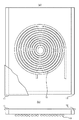
図2(a)は従来の電磁調理器の平面図、(b)はその側面図である。一般に電磁調理器は、図示するように、リッツ線などの導線を中心より外周に向かって渦巻状に密接して巻回した平形の加熱コイル10と、この加熱コイル10から10〜15mm程度離れた位置に配されたトッププレート11とを有する。このトッププレート11は、調理容器や調理板等の被加熱物を載置するもので、セラミック等の非磁性材で形成される。
【0003】
ところで、加熱コイル10に高周波電流を流して調理容器等を誘導加熱する際に、加熱コイル10自体あるいはトッププレート11が熱を持つ。そのため、この種の電磁調理器では、トッププレート11の背面周縁部を枠体12の厚み面に固定し、このトッププレート11の固定面以外の面部と加熱コイル10との間に放熱のための一定の冷却空間を形成しているのが通常である。
【0004】
【発明が解決しようとする課題】
上述のように、従来の電磁調理器は、冷却空間を確保するため枠体12の厚み面にトッププレート11の周縁部が固定される構造なので、トッププレート11の中央部付近の機械的強度が周縁部に比べて相対的に弱くなる。トッププレート11の厚みを増せば全体的な機械的強度は高まるが、反面、加熱コイル10と被加熱物との距離を大きくせざるを得ないので加熱効率が著しく低下する。そのため、このトッププレート11は、必要以上に厚くすることができず、割れ易くなる欠点があった。本発明はかかる欠点を解消することを目的とする。
【0005】
【課題を解決するための手段】
上記目的を達成する本発明の電磁調理器は、平形の加熱コイルと、この加熱コイルの被加熱物を載置するためのトッププレートと、このトッププレートを支持する複数の長尺薄板状のリブとを有し、各リブは、その主面同士が所定間隔で平行に向き合うように内部支持体に配列固定され、且つ、その一方の厚み面が前記加熱コイルを指向するとともに同一平面上に揃えられた他方の厚み面が前記トッププレートの背面に当接していることを特徴とする。
【0006】
なお、前記リブは好ましくは金属薄板であり、且つ隣設のリブと電気的に絶縁されているものとする。
【0007】
【作用】
本発明の電磁調理器では、複数のリブの厚み面がそれぞれトッププレートの背面に当接しているので、これら厚み面によってトッププレートの当接面が支持される。リブは、厚み面の強度がその主面よりも相対的に大きく、しかも所定間隔で配された複数のリブの厚み面によってトッププレートの当接面が支持されるため、被加熱物を載置する面に大きな力が加わってもこれを各リブに分散することができる。従って、トッププレートに局部的にかかる負荷を格段に小さくすることができ、リブが無い場合よりもトッププレートが割れにくくなる。
また、各リブの主面と当接面を除くトッププレートの背面とで冷却空間が形成されるので、従来通り放熱をも行うことができる。
【0008】
リブを金属薄板で形成する場合は、より十分な支持強度が得られるとともに、放熱効率も高まる。なお、この場合、加熱コイルを指向する厚み面が誘導を受け、渦電流が流れるが、この厚み面の面積が極小であり、磁界分布に与える影響や通電に伴う発熱量は僅かとなる。また、各リブはそれぞれ電気的に絶縁されているので、他のリブに流れる渦電流の影響を受けない。
【0009】
【実施例】
次に図面を参照して本発明の実施例を詳細に説明する。
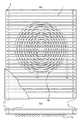
図1(a)は本発明の一実施例に係る電磁調理器の平面図、(b)はその側面図である。これらの図において、1はリブ、2はリブ端部を支持する絶縁性の支持体である。また、10は加熱コイル、11はトッププレートであり、図2に示した従来の電磁調理器と同一の構成要素である。
【0010】
本実施例の電磁調理器は、複数のリブ1をそれぞれ長尺状の硬銅薄板で形成するとともに、各リブ1の端部をそれぞれ所定間隔で支持体2の長辺部に配列固定し、隣設リブとの電気的接続を絶つようにしている。
このとき、各リブ1の一方の厚み面は加熱コイル10、他方の厚み面はトッププレート11を指向しており、各厚み面と垂直となる主面(リブの表裏面)同士は所定間隔で向き合っている。そして各リブ1の他方の厚み面が同一平面になるように主面同士の短辺幅を調節し、それぞれトッププレート11の背面(加熱コイル側の面)に当接する。これにより、トッププレート11の当接面以外の面部とリブ1の主面との間で一定の空間が形成されるので、この空間を放熱に用いることができる。
【0011】
リブ1の短辺幅は、トッププレート11の厚みと加熱効率との兼ね合いで決定する。例えば、トッププレート11の主面から加熱コイル10までの距離を15mm、加熱コイル10上の間隙を2mmとする場合において、トッププレート11の厚みが5mmであれば、リブ1の短辺幅は8mmとなる。また、リブ1の厚み面は1mm以下で足りるので、リブ1の存在による影響を余り受けずに誘導加熱が行われる。しかも加熱コイル10とトッププレート11との間は10mm程度離れているので十分な容積の冷却空間が確保される。
【0012】
このような構造の電磁調理器では、トッププレート11が複数のリブ1の厚み面にて支持されるため、トッププレート11に被加熱物を載置したときに加わる力や重量エネルギーが各リブ1や支持体2に分散され、リブ1の無い従来構造のものに比べてトッププレート11が割れにくくなる。また、リブ1の主面同士が所定間隔で向き合うように配列固定されているので、これら主面とトッププレート11の背面との間で冷却空間が形成され、従来通り放熱が行われる。
【0013】
リブ1は硬銅から成るので、高寿命をもって十分な支持強度が得られるとともに、熱伝導率にも優れているので、放熱効率も高まる。なお、使用時においては、各リブ1の加熱コイル10を指向する厚み面が誘導を受け、渦電流が流れるが、厚み面の面積が極小であり、磁界分布に与える影響や通電に伴う発熱量は僅かとなる。また、各リブ1は支持体2によってそれぞれ電気的に絶縁されているので、他のリブに流れる渦電流の影響を受けない。
【0014】
各リブ1の配列方向は、例えば図1(a)に示すように一定方向に揃えるのが好ましい。これは、図示しないファンから冷風を送り込み易くするとともに、この冷風を流通させ易くするためである。このように、冷風が流通する構造にすることにより放熱効率が更に高まる利点がある。
【0015】
また、各リブ1の配列間隔は任意で良いが、加熱コイル10又はトッププレート11の発熱量に応じて適当に疎密に変化させることもできる。
【0016】
以上、本発明を実施例を用いて説明したが、本発明は上記実施例に限定されることなく、その要旨を変更しない範囲で種々の設計変更が可能である。
例えば、リブ12は硬銅薄板に限らず、他の硬質金属板、例えば、非磁性ステンレス板やチタニウム板、多層板等で構成しても良く、あるいは主面に放熱フィンを付着するようにしても良い。また、リブ1を格子状あるいは多角形状に配列固定する構成にすることもできる。
【0017】
【発明の効果】
以上の説明から明らかなように、本発明の電磁調理器によれば、渦電流が流れにくく、しかも機械的強度の高い構造の複数のリブにてトッププレートが支持されるので、トッププレートを薄くしても割れにくくなる効果がある。
【0018】
また、リブの主面同士が所定間隔で向き合うように配列固定して冷却空間を形成するとともに各リブを金属薄板で形成したので、加熱効率を低下させることなく電磁調理器内部で発生した熱を効率的に放熱することができる。
【図面の簡単な説明】
【図1】(a)は本発明の第1実施例に係る電磁調理器の要部を示した平面図、(b)はその側面図である。
【図2】(a)は従来の一般的な電磁調理器の要部を示した平面図、(b)はその側面図である。
【符号の説明】
1 リブ
2 絶縁性支持体
10 加熱コイル
11 トッププレート
12 枠体[0001]
[Industrial application fields]
The present invention relates to an electromagnetic cooker provided with a top plate for placing an object to be heated, and more particularly to a structure for reinforcing the mechanical strength of the top plate.
[0002]
[Prior art]
Fig.2 (a) is a top view of the conventional electromagnetic cooking device, (b) is the side view. In general, as shown in the figure, the electromagnetic cooker is a
[0003]
By the way, when a high frequency current is passed through the
[0004]
[Problems to be solved by the invention]
As described above, the conventional electromagnetic cooker has a structure in which the peripheral portion of the
[0005]
[Means for Solving the Problems]
An electromagnetic cooker according to the present invention that achieves the above object includes a flat heating coil, a top plate for placing an object to be heated by the heating coil, and a plurality of long thin ribs that support the top plate. The ribs are arranged and fixed to the internal support so that their main surfaces face each other in parallel at a predetermined interval, and one thickness surface thereof is directed to the heating coil and aligned on the same plane. The other thickness surface is in contact with the back surface of the top plate.
[0006]
The rib is preferably a thin metal plate and is electrically insulated from the adjacent rib.
[0007]
[Action]
In the electromagnetic cooking device of the present invention, since the thickness surfaces of the plurality of ribs are in contact with the back surface of the top plate, the contact surfaces of the top plate are supported by these thickness surfaces. The rib has a thickness surface that is relatively stronger than the main surface, and the abutment surface of the top plate is supported by the thickness surfaces of a plurality of ribs arranged at predetermined intervals. Even if a large force is applied to the surface to be processed, it can be distributed to each rib. Therefore, the load locally applied to the top plate can be remarkably reduced, and the top plate is harder to break than when there is no rib.
Further, since the cooling space is formed by the main surface of each rib and the back surface of the top plate excluding the contact surface, heat can be radiated as usual.
[0008]
When the rib is formed of a thin metal plate, sufficient support strength can be obtained and the heat dissipation efficiency can be increased. In this case, the thickness surface directed to the heating coil is induced and eddy current flows, but the area of the thickness surface is minimal, and the influence on the magnetic field distribution and the amount of heat generated by energization are small. Moreover, since each rib is electrically insulated, it is not influenced by the eddy current which flows into another rib.
[0009]
【Example】
Next, embodiments of the present invention will be described in detail with reference to the drawings.
FIG. 1A is a plan view of an electromagnetic cooker according to one embodiment of the present invention, and FIG. In these drawings, 1 is a rib, and 2 is an insulating support that supports the end of the rib.
[0010]
The electromagnetic cooker of the present embodiment forms a plurality of ribs 1 with long hard copper thin plates, and arranges and fixes the ends of the ribs 1 on the long sides of the
At this time, one thickness surface of each rib 1 is directed to the
[0011]
The short side width of the rib 1 is determined based on the balance between the thickness of the
[0012]
In the electromagnetic cooker having such a structure, since the
[0013]
Since the rib 1 is made of hard copper, a sufficient support strength can be obtained with a long lifetime, and since the thermal conductivity is excellent, the heat dissipation efficiency is also increased. In use, the thickness surface of each rib 1 that faces the
[0014]
The arrangement direction of the ribs 1 is preferably aligned in a certain direction as shown in FIG. This is because it is easy to feed cool air from a fan (not shown) and to easily distribute this cool air. Thus, there exists an advantage which heat dissipation efficiency increases further by setting it as the structure where a cold wind distribute | circulates.
[0015]
Moreover, although the arrangement | sequence space | interval of each rib 1 may be arbitrary, according to the emitted-heat amount of the
[0016]
As mentioned above, although this invention was demonstrated using the Example, this invention is not limited to the said Example, A various design change is possible in the range which does not change the summary.
For example, the
[0017]
【The invention's effect】
As is clear from the above description, according to the electromagnetic cooking device of the present invention, the top plate is supported by a plurality of ribs having a structure in which eddy currents hardly flow and mechanical strength is high. Even if it has the effect of becoming hard to break.
[0018]
In addition, the ribs are arranged and fixed so that the main surfaces of the ribs face each other at a predetermined interval to form a cooling space and each rib is formed of a thin metal plate, so heat generated in the electromagnetic cooker can be reduced without reducing heating efficiency. Heat can be radiated efficiently.
[Brief description of the drawings]
FIG. 1A is a plan view showing a main part of an electromagnetic cooker according to a first embodiment of the present invention, and FIG. 1B is a side view thereof.
2A is a plan view showing a main part of a conventional general electromagnetic cooker, and FIG. 2B is a side view thereof.
[Explanation of symbols]
1
Claims (2)
Priority Applications (1)
| Application Number | Priority Date | Filing Date | Title |
|---|---|---|---|
| JP458594A JP3636484B2 (en) | 1994-01-20 | 1994-01-20 | Electromagnetic cooker |
Applications Claiming Priority (1)
| Application Number | Priority Date | Filing Date | Title |
|---|---|---|---|
| JP458594A JP3636484B2 (en) | 1994-01-20 | 1994-01-20 | Electromagnetic cooker |
Publications (2)
| Publication Number | Publication Date |
|---|---|
| JPH07211442A JPH07211442A (en) | 1995-08-11 |
| JP3636484B2 true JP3636484B2 (en) | 2005-04-06 |
Family
ID=11588124
Family Applications (1)
| Application Number | Title | Priority Date | Filing Date |
|---|---|---|---|
| JP458594A Expired - Lifetime JP3636484B2 (en) | 1994-01-20 | 1994-01-20 | Electromagnetic cooker |
Country Status (1)
| Country | Link |
|---|---|
| JP (1) | JP3636484B2 (en) |
Families Citing this family (1)
| Publication number | Priority date | Publication date | Assignee | Title |
|---|---|---|---|---|
| CN106018459A (en) * | 2016-05-25 | 2016-10-12 | 广西梧州日成林产化工股份有限公司 | Hot milling device for standard color lump and softening point circular block of rosin or rosin resin products |
-
1994
- 1994-01-20 JP JP458594A patent/JP3636484B2/en not_active Expired - Lifetime
Also Published As
| Publication number | Publication date |
|---|---|
| JPH07211442A (en) | 1995-08-11 |
Similar Documents
| Publication | Publication Date | Title |
|---|---|---|
| JP3938197B2 (en) | Induction heating device | |
| JP3990000B2 (en) | High efficiency induction cooking range | |
| KR970073225A (en) | Heating cooker using electromagnetic induction heating | |
| KR20180066870A (en) | Heating Module for induction range and induction range including the same | |
| JP3636484B2 (en) | Electromagnetic cooker | |
| US6121591A (en) | Flux guiding and cooling arrangements for induction heating units | |
| CN101437334B (en) | Induction heating cooking device | |
| JP2939554B2 (en) | Induction cooker | |
| EP0748577B1 (en) | Induction heating element | |
| CN221227766U (en) | Electromagnetic heating structure and cooking appliance | |
| JPH01313882A (en) | A device for protecting the electrodes of an electromagnetic induction device and an electromagnetic induction device equipped with this device | |
| JP4784130B2 (en) | Induction heating device | |
| JP3869892B2 (en) | Electromagnetic induction heating coil | |
| US12464608B2 (en) | Combined inductor shielding system | |
| JPH1140338A (en) | Electromagnetic induction heating device | |
| JPS636876Y2 (en) | ||
| CN211240153U (en) | Electromagnetic heating's coil pack, electromagnetic heating device and electromagnetic heating equipment | |
| JPH10335056A (en) | Electromagnetic induction heating coil | |
| JPH01239790A (en) | Inductive heating device of electromagnetic cooker | |
| JP4654167B2 (en) | Container to be heated | |
| JPH11204244A (en) | Induction heating cooker | |
| JP2587156B2 (en) | Induction heating coil | |
| JPS6355882A (en) | Heating coil for induction cooker | |
| WO2025200432A1 (en) | Heating apparatus and cooking utensil | |
| JPH0822888A (en) | Electromagnetic cooker |
Legal Events
| Date | Code | Title | Description |
|---|---|---|---|
| A977 | Report on retrieval |
Free format text: JAPANESE INTERMEDIATE CODE: A971007 Effective date: 20041222 |
|
| TRDD | Decision of grant or rejection written | ||
| A01 | Written decision to grant a patent or to grant a registration (utility model) |
Free format text: JAPANESE INTERMEDIATE CODE: A01 Effective date: 20050104 |
|
| A61 | First payment of annual fees (during grant procedure) |
Free format text: JAPANESE INTERMEDIATE CODE: A61 Effective date: 20050105 |
|
| R150 | Certificate of patent (=grant) or registration of utility model |
Free format text: JAPANESE INTERMEDIATE CODE: R150 |
|
| FPAY | Renewal fee payment (prs date is renewal date of database) |
Year of fee payment: 4 Free format text: PAYMENT UNTIL: 20090114 |
|
| FPAY | Renewal fee payment (prs date is renewal date of database) |
Free format text: PAYMENT UNTIL: 20090114 Year of fee payment: 4 |
|
| FPAY | Renewal fee payment (prs date is renewal date of database) |
Year of fee payment: 5 Free format text: PAYMENT UNTIL: 20100114 |
|
| FPAY | Renewal fee payment (prs date is renewal date of database) |
Free format text: PAYMENT UNTIL: 20110114 Year of fee payment: 6 |
|
| FPAY | Renewal fee payment (prs date is renewal date of database) |
Year of fee payment: 7 Free format text: PAYMENT UNTIL: 20120114 |
|
| FPAY | Renewal fee payment (prs date is renewal date of database) |
Year of fee payment: 7 Free format text: PAYMENT UNTIL: 20120114 |
|
| FPAY | Renewal fee payment (prs date is renewal date of database) |
Free format text: PAYMENT UNTIL: 20120114 Year of fee payment: 7 |
|
| FPAY | Renewal fee payment (prs date is renewal date of database) |
Free format text: PAYMENT UNTIL: 20130114 Year of fee payment: 8 |
|
| EXPY | Cancellation because of completion of term |