JP3634954B2 - Synthetic plastic bag - Google Patents
Synthetic plastic bag Download PDFInfo
- Publication number
- JP3634954B2 JP3634954B2 JP34361497A JP34361497A JP3634954B2 JP 3634954 B2 JP3634954 B2 JP 3634954B2 JP 34361497 A JP34361497 A JP 34361497A JP 34361497 A JP34361497 A JP 34361497A JP 3634954 B2 JP3634954 B2 JP 3634954B2
- Authority
- JP
- Japan
- Prior art keywords
- rib
- chuck
- discontinuous
- ribs
- opening
- Prior art date
- Legal status (The legal status is an assumption and is not a legal conclusion. Google has not performed a legal analysis and makes no representation as to the accuracy of the status listed.)
- Expired - Lifetime
Links
Images


Description
【0001】
【発明の属する技術分野】
本発明は、開口部に雌雄爪型のチャックを備えた合成樹脂製袋体の改良に関するものである。
【0002】
【従来の技術】
開口部に再開閉機能を持つ雌雄爪型のチャックを備えた合成樹脂製袋体は各種の物品の包装に広く用いられている。
【0003】
【発明が解決しようとする課題】
この種の袋体は、インフレーション成形法あるいはTダイ成形法でフィルムとチャックを一体成形したチャック付きフィルム又は既成のフィルム上にチャックを押し出し成形し、直接フィルムに溶着したチャック付きフィルムを製袋機により単体の袋体を連続的に生産している。
【0004】
ところで、前記チャック付きフィルムの段階でフィルムとチャックの冷却速度差あるいはチャック冷却過程での収縮により、チャック基部周辺のフィルムに縮みが発生し、これがシワとなって品質を低下する。
【0005】
また、フィルムが軟質であったり、薄いフィルムの場合は、前記フィルムの収縮がチャックに波及してチャックが傾斜,捩じれ,曲がり,波打ち等の変形が生じ易く、チャックの雌雄爪の咬合が困難となる。
【0006】
本発明の目的は、チャック周辺のフィルムを補強してチャックの変形を防止し、且つ開口部の拡開を容易にした合成樹脂製袋を提供することである。
【0007】
【課題を解決するための手段】
上記目的を達成するための本発明の構成は、請求項1に記載の通り、開口部の内側面に雌雄爪型のチャックを備えた合成樹脂製袋体において、前記チャック位置の上部又は上下部に任意の間隔で凹欠部を形成した1条又は複数条の不連続線のリブ条を前記チャックと平行に突設したことを特徴とするものである。
【0008】
また、上記目的を達成するための本発明の構成は、請求項2に記載の通り、開口部の内側面に雌雄爪型のチャックを備えた合成樹脂製袋体において、前記チャック位置の上部又は上下部に任意の間隔で凹欠部を形成した不連続線のリブ条と凹欠部を形成していない連続線のリブ条との混交リブ条を前記チャックと平行に突設したことを特徴とするものである。
【0009】
【発明の実施の形態】
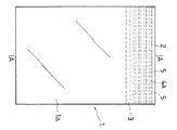
以下本発明の実施の形態を図面に基づいて説明する。図1及び図2において、1は対面する合成樹脂のフィルム1a,1bによって形成されている袋体であり、開口部2の内側面には開口の際に指先で把持する把持部を残して再開閉可能な雌雄爪型のチャック3を備えている。
【0010】
図1及び図2で示す実施形態では、袋体1の前記チャック3の位置より上方のフィルム1a,1bの内側面に任意の間隔で凹欠部5を形成した1条又は複数条の不連続線のリブ条4aを前記チャック3と平行に突設したものである。
【0011】
前記図1及び図2の実施形態における複数条の不連続線のリブ条4aの凹欠部5は全て同一位相にしているが、図3で示すように、複数条の不連続線のリブ条4aの凹欠部5が互い違いとなるよう位相をずらせてもよい。
【0012】
また、図1及び図3は全部が凹欠部5を形成した複数の不連続線のリブ条4aであるが、1条の不連続線のリブ条4aでもよいし、図4で示すように、凹欠部5を形成した不連続線のリブ条4aと凹欠部5を形成していない連続線のリブ条4bとの混交リブ条の構成としてもよい。
【0013】
さらに、図5で示すようにチャック3の位置より下方のフィルム1a,1bの内側面に不連続線のリブ条4aあるいは不連続線のリブ条4aと連続線のリブ条4bとの混交リブ条を突設してもよい。
【0014】
また、上記図示した不連続線のリブ条4aあるいは不連続線のリブ条4aと連続線のリブ条4bとの混交リブ条は、フィルム1a,1bの内側面に突設した形態であるが、外側面、内外両側面あるいはチャック3の位置より上方は内側面でチャック3の位置より下方は外側面又はチャック3の位置より上方は外側面でチャック3の位置より下方は内側面でもよい。
【0015】
さらにまた、上記不連続線のリブ条4aあるいは不連続線のリブ条4aと連続線のリブ条4bとの混交リブ条は、フィルム1a,1bに直接設けてもよいし、不連続線のリブ条4aあるいは不連続線のリブ条4aと連続線のリブ条4bとの混交リブ条を形成したテープ材をフィルム1a,1bに一体化する形で設けてもよい。
【0016】
上記不連続線のリブ条4aの成形方法について図7乃至図10で説明する。図9で示すように、連続線のリブ条4bを突設したフィルム1a,1bを成形し、これを図7で示すように、円周上に所定のピッチで突起7を突設したローラ6によって前記連続線のリブ条4bを押えることにより、突起7によって凹欠部5が形成され、図10で示す不連続線のリブ条4aが得られる。
【0017】
また、図8で示すように、フィルム1a,1bの間に緩衝材8を介在し、平面に所定のピッチで突起10を突設した上方熱バー9aと下方熱バー9bとによって連続線のリブ条4bをプレスすることにより図10で示す不連続線のリブ条4aが得られる。
【0018】
凹欠部5を形成した不連続線のリブ条4aと凹欠部5を形成していない連続線のリブ条4bとの混交リブ条は、ローラ6に突起7を又は熱バー9a,9bに突起10を突設しない部分を形成し、一部の連続線のリブ条4bに凹欠部5を形成しないようにすることで混交リブ条が得られる。
【0019】
上記の構成による本発明の合成樹脂袋体は、不連続線のリブ条4aあるいは不連続線のリブ条4aと連続線のリブ条4bとの混交リブ条によってチャック3の周辺のフィルム1a,1bが補強され、フィルム1a,1bの収縮を抑止し、チャック3の傾斜,捩じれ,曲がり,波打ち等の変形が防止され、チャック3の雌雄爪の咬合を容易にする。
【0020】
また、前記チャック3の周辺を不連続線のリブ条4aあるいは不連続線のリブ条4aと連続線のリブ条4bとの混交リブ条によって補強することにより剛性が付与され、フィルム1a,1bが軟質であったり、薄い場合でもチャック3の開閉操作性を向上する。
【0021】
さらに、不連続線のリブ条4aあるいは不連続線のリブ条4aと連続線のリブ条4bとの混交リブ条によって、開口部2を含むチャック3の周辺は前記のように剛性が付与されているものの、不連続線のリブ条4aの凹欠部5によって柔軟性を有している。
【0022】
この剛性と柔軟性とを兼ね備えていることにより、開口部2を筒状に容易に拡開することができる。すなわち、リブ条4aによって剛性を付与し凹欠部5では柔軟性を有しているため、袋体1の幅方向の両側から中央に向けて力を加えることにより開口部2は容易に拡開し、且つ筒状に拡開した形態を保持し内容物の取り出しや充填等を容易にする。この作用は、不連続線のリブ条4aと連続線のリブ条4bとの混交リブ条の方が有利である。
【0023】
前記不連続線のリブ条4aあるいは不連続線のリブ条4aと連続線のリブ条4bとの混交リブ条による剛性と柔軟性はリブ条の高さによる調整だけでなく凹欠部5のピッチあるいは長さ及び条数によって調整することができ、フィルム1a,1bの材料や袋体1のサイズ及び用途に応じて適宜設定する。
【0024】
さらに本発明による合成樹脂袋体は図6で示すように、開口部2を袋体1の外側に折り返して開口する場合にも不連続線のリブ条4aあるいは不連続線のリブ条4aと連続線のリブ条4bとの混交リブ条による剛性の弾性作用と凹欠部5の柔軟性とによって筒状に拡開した形態を保持し内容物の取り出しや充填等を容易にする。
【0025】
【発明の効果】
以上のように本発明によると、チャックの周辺のフィルムを不連続線のリブ条あるいは不連続線のリブ条と連続線のリブ条との混交リブ条によって補強することにより、チャックの変形を防止してチャックの咬合を容易にすると共に、開閉操作性を向上する。また、不連続線のリブ条あるいは不連続線のリブ条と連続線のリブ条との混交リブ条による剛性と柔軟性とによって開口部を容易に拡開し、且つ筒状に拡開した形態を保持して内容物の取り出しや充填等を容易にする利点を有している。
【図面の簡単な説明】
【図1】本発明の袋体の正面図
【図2】図1のA−A線断面図
【図3】不連続線のリブ条の配列の設計変更例を示す図
【図4】不連続線のリブ条と連続線のリブ条との混交リブ条の配列を示す図
【図5】リブ条をチャックの上下部に設けた例の断面図
【図6】開口部を袋体の外側に折り返して開口した状態の断面図
【図7】不連続線のリブ条の製造方法の説明図
【図8】不連続線のリブ条の他の製造方法の説明図
【図9】不連続線のリブ条の製造前の斜視図
【図10】不連続線のリブ条の製造後の斜視図
【符号の説明】
1 袋体
2 開口部
3 チャック
4a 不連続線のリブ条
4b 連続線のリブ条
5 凹欠部[0001]
BACKGROUND OF THE INVENTION
The present invention relates to an improvement of a synthetic resin bag body having a male and female nail type chuck in an opening.
[0002]
[Prior art]
Synthetic resin bags having a male and female nail type chuck having a reopening / closing function at the opening are widely used for packaging various articles.
[0003]
[Problems to be solved by the invention]
This type of bag body is a bag making machine that forms a film with a chuck by integrally forming a film and a chuck by an inflation molding method or a T-die molding method, or extruding a chuck onto an existing film and directly welding the film with a chuck to the film. The single bag body is continuously produced.
[0004]
By the way, due to the difference between the cooling rate of the film and the chuck at the stage of the film with the chuck or the shrinkage in the chuck cooling process, the film around the chuck base is shrunk, which becomes a wrinkle and deteriorates the quality.
[0005]
In addition, when the film is soft or thin, the shrinkage of the film affects the chuck, and the chuck tends to be inclined, twisted, bent, undulated, etc., and it is difficult to bite the male and female nails of the chuck. Become.
[0006]
An object of the present invention is to provide a synthetic resin bag that reinforces the film around the chuck to prevent deformation of the chuck and facilitates the opening of the opening.
[0007]
[Means for Solving the Problems]
In order to achieve the above object, according to the first aspect of the present invention, there is provided a synthetic resin bag body having a male and female nail type chuck on the inner side surface of the opening. In addition, one or a plurality of discontinuous rib ribs having recesses formed at arbitrary intervals are provided in parallel with the chuck.
[0008]
Further, according to a second aspect of the present invention, there is provided a synthetic resin bag body having a male and female nail type chuck on an inner surface of an opening, as described in
[0009]
DETAILED DESCRIPTION OF THE INVENTION
Embodiments of the present invention will be described below with reference to the drawings. 1 and 2,
[0010]
In the embodiment shown in FIG. 1 and FIG. 2, one or a plurality of discontinuities in which
[0011]
1 and 2 are all in the same phase, but as shown in FIG. 3, the ribs of a plurality of discontinuous lines are in the same phase. The phase may be shifted so that the recessed portions 5a of 4a are staggered.
[0012]
1 and 3 show a plurality of
[0013]
Further, as shown in FIG. 5,
[0014]
Further, the
[0015]
Furthermore, the
[0016]
A method for forming the
[0017]
Further, as shown in FIG. 8, a continuous line rib is formed by an
[0018]
The mixed rib strip of the
[0019]
The synthetic resin bag body of the present invention having the above-described configuration is formed by
[0020]
Further, rigidity is provided by reinforcing the periphery of the
[0021]
Further, the periphery of the
[0022]
By combining this rigidity and flexibility, the
[0023]
The rigidity and flexibility of the
[0024]
Furthermore, as shown in FIG. 6, the synthetic resin bag according to the present invention is continuous with the
[0025]
【The invention's effect】
As described above, according to the present invention, deformation of the chuck is prevented by reinforcing the film around the chuck with discontinuous rib strips or mixed rib strips of discontinuous rib strips and continuous rib strips. As a result, the chuck can be easily bitten and the opening / closing operability can be improved. In addition, the opening is easily expanded by the rigidity and flexibility of the ribs of discontinuous lines or the mixed ribs of the ribs of discontinuous lines and the ribs of continuous lines, and a form in which the opening is expanded into a cylindrical shape It has the advantage of facilitating the removal and filling of the contents while holding.
[Brief description of the drawings]
1 is a front view of a bag according to the present invention. FIG. 2 is a cross-sectional view taken along line AA in FIG. 1. FIG. 3 is a diagram showing a design change example of an arrangement of ribs of discontinuous lines. FIG. 5 is a cross-sectional view of an example in which rib strips are provided on the upper and lower portions of the chuck. FIG. 6 is an opening on the outside of the bag body. FIG. 7 is an explanatory view of a manufacturing method of a rib strip of a discontinuous line. FIG. 8 is an explanatory diagram of another manufacturing method of a rib strip of a discontinuous line. Perspective view before manufacturing rib ribs [Fig. 10] Perspective view after manufacturing rib ribs with discontinuous lines [Explanation of symbols]
DESCRIPTION OF
Claims (2)
Priority Applications (1)
| Application Number | Priority Date | Filing Date | Title |
|---|---|---|---|
| JP34361497A JP3634954B2 (en) | 1997-12-01 | 1997-12-01 | Synthetic plastic bag |
Applications Claiming Priority (1)
| Application Number | Priority Date | Filing Date | Title |
|---|---|---|---|
| JP34361497A JP3634954B2 (en) | 1997-12-01 | 1997-12-01 | Synthetic plastic bag |
Publications (2)
| Publication Number | Publication Date |
|---|---|
| JPH11165744A JPH11165744A (en) | 1999-06-22 |
| JP3634954B2 true JP3634954B2 (en) | 2005-03-30 |
Family
ID=18362902
Family Applications (1)
| Application Number | Title | Priority Date | Filing Date |
|---|---|---|---|
| JP34361497A Expired - Lifetime JP3634954B2 (en) | 1997-12-01 | 1997-12-01 | Synthetic plastic bag |
Country Status (1)
| Country | Link |
|---|---|
| JP (1) | JP3634954B2 (en) |
Families Citing this family (7)
| Publication number | Priority date | Publication date | Assignee | Title |
|---|---|---|---|---|
| US6186663B1 (en) * | 1999-08-17 | 2001-02-13 | Illinois Tool Works Inc. | Gusseted package with reclosable zipper |
| AU7400900A (en) * | 1999-10-11 | 2001-04-23 | Zip Pack Ip Ag | Tearable guarantee closure |
| JP2003040290A (en) * | 2001-07-30 | 2003-02-13 | Fuji Seal Inc | Pouch container |
| US20090097782A1 (en) * | 2007-10-15 | 2009-04-16 | Illinois Tool Works Inc. | Method for producing perforated zipper for transverse direction zipper applicator |
| JP5966134B2 (en) * | 2011-04-25 | 2016-08-10 | ゼネラルパッカー株式会社 | Packaging bag and its manufacturing method |
| JP6086673B2 (en) * | 2012-08-22 | 2017-03-01 | シーアイ化成株式会社 | Fitting tool and bag with fitting tool |
| CN104354973B (en) * | 2014-10-29 | 2017-02-15 | 湖北华强科技有限责任公司 | Zipper with rigid supporting structural members |
-
1997
- 1997-12-01 JP JP34361497A patent/JP3634954B2/en not_active Expired - Lifetime
Also Published As
| Publication number | Publication date |
|---|---|
| JPH11165744A (en) | 1999-06-22 |
Similar Documents
| Publication | Publication Date | Title |
|---|---|---|
| JP4316015B2 (en) | Resealable plastic bag with zipper with end stopper | |
| US5839831A (en) | Flexible package having improved gripper ridges and methods thereof | |
| JP2840498B2 (en) | Method of linearizing the heat seal part in a plastic film zipper bag | |
| US7409750B2 (en) | Plastic zipper with end stops and method for manufacturing same | |
| JP2005506938A (en) | Storage bag with mouth biased to open | |
| JP3634954B2 (en) | Synthetic plastic bag | |
| KR930001030B1 (en) | Method of forming a reclosable container with grip strip | |
| JP3643472B2 (en) | Synthetic plastic bag | |
| JP2557256Y2 (en) | Zippered bag | |
| AU770806B2 (en) | Container with closure device and gripping surface | |
| JP3025920U (en) | Multiple item binding packaging | |
| JPH0734823Y2 (en) | Wrap film storage case | |
| JP3732261B2 (en) | Plastic molded body and packaging body | |
| JP4334694B2 (en) | Bottle necker | |
| JP3790631B2 (en) | Method for forming irregularities in packaging bag and dispensing passage | |
| JP3300979B2 (en) | Bag with synthetic resin zipper | |
| JP3835835B2 (en) | Precision parts storage container | |
| JPH04118341U (en) | Packaging bag with closing string | |
| JP3046153B2 (en) | Resin cap with pill fur proof characteristics | |
| JP4380504B2 (en) | Rice ball molding machine and rice ball molding method | |
| JP2820449B2 (en) | Sealing lid | |
| JPH0751346Y2 (en) | Case | |
| JP3068283U (en) | Shoe holder | |
| JPH08310550A (en) | Packaging container with cover | |
| JPH06219454A (en) | Self-standing rectangular-bottomed bag |
Legal Events
| Date | Code | Title | Description |
|---|---|---|---|
| A977 | Report on retrieval |
Free format text: JAPANESE INTERMEDIATE CODE: A971007 Effective date: 20040901 |
|
| A131 | Notification of reasons for refusal |
Free format text: JAPANESE INTERMEDIATE CODE: A131 Effective date: 20040907 |
|
| TRDD | Decision of grant or rejection written | ||
| A01 | Written decision to grant a patent or to grant a registration (utility model) |
Free format text: JAPANESE INTERMEDIATE CODE: A01 Effective date: 20041221 |
|
| A61 | First payment of annual fees (during grant procedure) |
Free format text: JAPANESE INTERMEDIATE CODE: A61 Effective date: 20041227 |
|
| R150 | Certificate of patent or registration of utility model |
Free format text: JAPANESE INTERMEDIATE CODE: R150 |
|
| FPAY | Renewal fee payment (event date is renewal date of database) |
Free format text: PAYMENT UNTIL: 20110107 Year of fee payment: 6 |
|
| FPAY | Renewal fee payment (event date is renewal date of database) |
Free format text: PAYMENT UNTIL: 20110107 Year of fee payment: 6 |
|
| FPAY | Renewal fee payment (event date is renewal date of database) |
Free format text: PAYMENT UNTIL: 20140107 Year of fee payment: 9 |
|
| FPAY | Renewal fee payment (event date is renewal date of database) |
Free format text: PAYMENT UNTIL: 20140107 Year of fee payment: 9 |
|
| S531 | Written request for registration of change of domicile |
Free format text: JAPANESE INTERMEDIATE CODE: R313531 |
|
| FPAY | Renewal fee payment (event date is renewal date of database) |
Free format text: PAYMENT UNTIL: 20140107 Year of fee payment: 9 |
|
| R350 | Written notification of registration of transfer |
Free format text: JAPANESE INTERMEDIATE CODE: R350 |
|
| R250 | Receipt of annual fees |
Free format text: JAPANESE INTERMEDIATE CODE: R250 |
|
| R250 | Receipt of annual fees |
Free format text: JAPANESE INTERMEDIATE CODE: R250 |
|
| EXPY | Cancellation because of completion of term |