JP3634429B2 - Manufacturing method of bag-in carton - Google Patents
Manufacturing method of bag-in carton Download PDFInfo
- Publication number
- JP3634429B2 JP3634429B2 JP02678695A JP2678695A JP3634429B2 JP 3634429 B2 JP3634429 B2 JP 3634429B2 JP 02678695 A JP02678695 A JP 02678695A JP 2678695 A JP2678695 A JP 2678695A JP 3634429 B2 JP3634429 B2 JP 3634429B2
- Authority
- JP
- Japan
- Prior art keywords
- carton
- inner bag
- bag
- pair
- seal
- Prior art date
- Legal status (The legal status is an assumption and is not a legal conclusion. Google has not performed a legal analysis and makes no representation as to the accuracy of the status listed.)
- Expired - Fee Related
Links
Images


Description
【0001】
【産業上の利用分野】
本発明は略直方体状のカートン内面に、可撓性内袋を貼り付けてなるバッグインカートンの製造方法に関する。
【0002】
【従来の技術】
従来、液体包装容器としてバッグインカートンが使用されている。通常、バッグインカートンのカートンは、平坦な底面及び頂面と、その間の平坦な4側面とを有する略直方体形状をなしており、内袋はカートンの4側面の内面に貼り付けられている。このバッグインカートンは、一般にジュース、酒等の粘度の低い液体包装用として使用されており、内容物を注出口から取り出す際には、内容物の排出に伴い、その排出分に相当する空気が内袋内に入るように取り扱われている。
【0003】
【発明が解決しようとする課題】
バッグインカートンをインキ等の高粘度の液体包装用に使用する場合、高粘度液体の取り出しに当たって液体を注出口から吸引して取り出す必要があり、その際空気を内袋内に入れることが困難である。このため、内袋を内容物の取り出しに応じて容積が減少するように変形させる必要がある。従って従来のように内袋をカートンの4側面に貼り付けた形式のバッグインカートンでは、内容物の取り出し時に内袋が変形できず、結局、そのままでは高粘度液体の包装には用いることができない。
【0004】
このような場合、カートン内部に内袋を変形自在に設けてなるバッグインカートンが考えられている。内袋は一般に、筒状フィルムの両側開口をシールして密閉され、密閉された内袋がカートン内部に収納される。
【0005】
しかしながら、内袋のシール密閉部は形状が定まらず、とりわけカートン内部で不均一な形状となることがあり、この場合は内袋の内容積が一定に保たれないことが考えられる。
【0006】
さらに、バッグインカートンを印刷機用インキの包装用に使用する場合、インキをポンプ等の機械装置(吸引装置)により自動的に吸引させることになる為、容器の選定にあたって、以下の事項を考慮する必要がある。
【0007】
▲1▼印刷インキには印刷性・保存性等の種類の機能が求められる為、その組成は、極めて多成分系で複雑になることが一般的である。
【0008】
内袋は、これらのいづれの成分に対してもバリアー性を確保する必要がある為、多層構造の素材が選定される事が多い。
【0009】
その為、結果的に素材は剛度が高くなり、さらに、シール部分は素材が二層になるので、硬質になる。
【0010】
▲2▼容器にインキを充填する際は、一定の重量もしくは容量を流量計等で測定しながら、規定された充填圧力のもとでインキ入れることになる。
【0011】
その為、規定されたインキの充填圧力のもとで、安定した内袋収納状態、容量を示す内袋の形状でないと、結果として容器の中にインキ以外の空気の「溜まり」が残る事になり、残量も多くなり残量バラツキも大きくなる。
【0012】
▲3▼バッグインカートンを印刷機に装着した場合、インキはポンプ等の機械装置で自動的に吸引される為、容器中にインキの他に空気が残っていると、単位時間あたりの吸引量がばらつき、印刷物がかすれるというような障害が生じることになる。
【0013】
▲4▼バッグインカートンを使用した後の残量が少なくなることが望まれる。
【0014】
本発明はこのような点を考慮してなされたものであり、インキ等の高粘度液体を、適切に包装することができるとともに、内袋の内容積を一定に保つことができ、内袋の収納状態を常に均一とし残量を少なく安定させることが可能なバッグインカートンの製造方法を提供することを目的とする。
【0015】
【課題を解決するための手段】
本発明は、カートン成形用のカートンブランクの所定位置に、筒状フィルムからなる可撓性内袋を粘着する工程と、カートンブランクを角柱状に起こして両側に開口を有するカートンを組立てる工程と、カートンの一側開口に位置する内袋の一側開口を直線状にシールして一対の三角フラップを形成する工程と、内袋の一側開口に形成された一対の三角フラップの基端を各々シールして一側シール密閉部を形成する工程と、内袋の一対の三角フラップを内方に折畳んだ後、カートンの一側開口を折畳んで密閉して、一側密閉部を形成する工程と、を備え、カートンの一側密閉部を形成した後、カートンの他側開口および内袋の他側開口から成形治具を内袋内に挿入し、この成形治具により内袋の一側シール密閉部をカートンの一側密閉部に押し付け、内袋の一側シール密閉部をカートンの一側密閉部に合わせて成形する工程を更に備えたことを特徴とするバッグインカートンの製造方法である。
【0016】
【作用】
本発明によれば、内袋の一側開口を直線状にシールして一対の三角フラップを形成し、この一対の三角フラップの基端を各々シールして一側シール密閉部を形成したので、三角フラップ内に内容物が入り込んでその分内容物の残留が多くなることはない。
【0017】
【実施例】
以下、図面を参照して本発明の実施例について説明する。
【0018】
図1乃至図8は本発明によるバッグインカートンおよびその製造方法の一実施例を示す図である。まず図1乃至図4によりバッグインカートンの概略を説明する。このうち図1(a)はバッグインカートンの内容物を満たした状態を、図1(b)はバッグインカートンの内容物を吸い出した状態を示している。また図2はバッグインカートンの概略斜視図である。図1、図2において、バッグインカートンは、外容器を構成する略直方体状の箱状カートン2と、その内部に収容された可撓性の内袋3とを備え、その内袋3内にインキ等の液体からなる内容物4が収容されている。カートン2は、直方体の隣合う二面間に傾斜面を形成したものであり、カートン2は、平坦な四つの側面2a、2b、2c、2dと、端面2e、2fと、端面2fと側面2aとの間に形成された傾斜面2gとを有している。
【0019】
カートン2の傾斜面2gには、内袋3に連通する注出口5が取り付けられ、注出口5はキャップ6で閉じられている。この注出口5は、内袋3内に延びる筒状部5aを有しており、その筒状部5aの内袋3側端部に液体を通過させるための溝状の通路5bが形成されている。この通路5bを形成したことにより、例え、筒状部5aの先端が内袋3で塞がれたとしても、内容物4を注出口5に吸い込むことが可能である。注出口5のカートン2からの突出高さは、キャップ6を取り付けた状態でそのキャップ6が、側面2a及び端面2fの各延長面で囲まれた領域内に入るように定められている。このような構成により、多数のバックインカートンを並べ且つ積み重ねることができる。
【0020】
内袋3はカートン2の内面に対して一部が貼り付けられ、動かないように固定されている。
【0021】
すなわち、図1乃至図3に示すように、内袋3はカートン2の内面のうち、傾斜面(注出口取付面)2g、傾斜面2gに隣接するとともに互いに対向する一対の側面2b、2d、および傾斜面2gの下方に隣接する側面2aの略全域に粘着されている。また内袋3は傾斜面2gと隣接しない離れた面のうち、側面2cにも部分的に粘着されている。図2において、内袋3の粘着領域9が示されている。また、図3はカートン成形用のカートンブランク2′を示しており、図3において粘着領域9のうち、二方向のハッチング部分は剥離しない非剥離領域であり、一方向のハッチング部分は剥離領域である。
【0022】
このように、カートン2の内面のうち、内袋3を傾斜面2g、一対の側面2b、2d、および傾斜面2g下方の側面2aの略全域に粘着するとともに、側面2cにも部分的に粘着することにより、内袋3をカートン2内において堅固に固定することができる。また、カートン2と内袋3との粘着は、剥離自在の接着剤により行われる。このため、内容物4の減少とともに、内袋3を収納させて内袋3をカートン2から容易に剥離させることができる。
【0023】
なお、側面2cに対して内袋3は、粘着領域9において粘着されている。注出口5から内容物4を取出す際、内袋3は徐々に変形して注出口5方向へ移動するが、この場合、内袋3はまず注出口5から離れた側面2cから剥離し始めるので、側面2cに内袋3を点付けすることにより、内袋3を側面2cから容易に剥離させることができる。側面2cにおける内袋3の粘着領域9は、図3に示すように正方形でもよく、また長方形でもよい。
【0024】
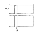
次に、上記構成のバッグインカートン1の製造方法を説明する。まず、図3において、板紙を所定形状に打ち抜いて、カートンを成形するためのカートンブランク2′を準備する。なお、このカートンブランク2′のパネル2a′、2b′、2c′、2d′、2g′(カートン2の側面2a、2b、2c、2d、および傾斜面2gとなる領域)の内面に粘着領域9が形成されている。図4に示すように、カートンブランク2′の製造と並行して、フィルムを筒状に折曲げてその端縁を筒貼りし(背シールし)、この背シールにより背シール部16を形成するとともに、所定の長さに切断した筒状フィルム3′(後工程でその上下端をシールして内袋となる)を準備する。
【0025】
次にカートンブランク2′のパネル2a′、2b′、2d′、およびパネル2g′の各々の略全域に形成された粘着領域9に接着剤、例えば、酢酸ビニル系、アクリル共重合体系、酢酸ビニル・アクリル共重合体系、変性アクリル酸エステル共重合体系等のエマルジョン型接着剤を塗布する。また、パネル2c′および糊代2h′の各々に部分的形成された粘着領域9に接着剤を塗布する。なお、カートンブランク2′の糊代2i′はカートンを組み立てる際、内側に折り込まれる部分であり、この糊代2i′にも接着剤、例えば、エチレン・酢酸ビニル共重合体系、ポリ酢酸ビニル系、ポリアミド系、ポリエチレン系、スチレン・ブタジェン共重合体系、スチレン・イソプレン共重合体系、ポリイソブチレン系、ポリエステル系等のホットメルト型接着剤が塗布される。また、糊代2h′の背面にも糊代2i′と同様の接着剤が塗布される。
【0026】
次に、図3に示すように、そのカートンブランク2′のパネル2a′、2d′、2g′に、接着剤を利用して筒状フィルム3′を貼り付ける。この場合、筒状フィルム3′は、その背シール部16がカートンブランク2′を組立てた際に側面2cに当接するとともに注出口5に対向する位置にくるよう配置される。次に、カートンブランク2′のパネル2b′、2c′を、筒状フィルム3′上に折り重ねて胴貼りし、且つパネル2b′、2c′及び糊代2h′を筒状フィルム3′に貼り付けるとともにパネル2b′とパネル2h′を貼り付ける。以上により、組み立て前の偏平なバッグインカートンが形成される。
【0027】
次に偏平なバッグインカートン1は組み立て及び充填工程に送られ、この組み立て及び充填工程においてバッグインカートン1が組立てられ内容物が充填される。バッグインカートンの組立て工程について図5乃至図8により説明する。
【0028】
まず、図5(a)に示すように、バッグインカートン1が支持部27によって支持されながら角柱状に起こして組立てられ、カートン2の両側(上下方向両側)に開口が形成されるとともに、内袋3の両側にも開口が形成される。図5(a)において、カートン2は両側の開口部に、一側パネル24および他側パネル25を有している。
【0029】
次に図5(b)に示すように、カートン2の上部開口(一側開口)から一対のアーム28が降下する。次にこの一対のアーム28が内袋3内に進入して内袋3を押し拡げ、その後図示しないアームにより他側パネル25が拡げられる(図5(c))。
【0030】
次に図5(d)に示すように、カートン2の一側開口から雌型29が降下して内袋3内に進入し、次に雌型29に対して雄型30が接近し、雌型29と雄型30との間でカートン2の注出口取付部分15(図3参照)が打抜かれる。
【0031】
その後、図6(a)に示すように、打抜かれた注出口取付部分15に対して光電管31によって注出口取付部分15が打抜かれたか否かを確認する。次に図6(b)に示すように、注出口5を保持した注出口保持部32がカートン2の一側開口から降下して内袋3内に進入し、更に注出口保持部32が注出口取付部分15側へ移動して注出口5をカートン2に取付ける。
【0032】
その後、図6(c)に示すように、光電管33によって注出口5が取付けられたか否かを確認する。次に図6(d)に示すように、超音波発振器34が注出口5側へ接近し、同時に起音波受振器35がカートン2の一側開口から降下して内袋3内に進入する。この状態で起音波発振器34から超音波が出力され、注出口5がカートン2に超音波シールされて固定される。
【0033】
その後、図7(a)に示すように、カートン2の一側開口から一対のアーム41が降下し、内袋3内に進入して内袋3を押し拡げる。同時にカートン用爪部42がカートン2に接近し、カートン2の一側パネル24を押し拡げる。
【0034】
次に図7(b)に示すように、一対のシール用アーム44がカートン2の一側開口から降下し、内袋3内に進入して内袋3の一側開口を押し拡げる。同時に図7(e)に示す一対の押えバー46および一対のシールバー47が、内袋3の一側開口に接近し、一対のシール用アーム44によって押し拡げられた内袋3の一側開口を、まず一対の押えバー46が押える。次に一対のシールバー47が内袋3の一側開口を直線状にシールして、この内袋3の一側開口に直線状の第1シール部10を形成する。この場合、内袋3の第1シール部10により一対の三角フラップ11が形成される。なお図7(e)は、図7(b)に示す内袋10を矢印E方向からみた図である。
【0035】
次に図7(c)に示すように、内袋3の一側開口に形成された第1シール部10が、冷却バー(図示せず)により冷却され、その後図7(d)に示すように内袋3の第1シール部10の上面に、一対の側板48aを有する保持板48を配置する。
【0036】
次に一対の側板48aに対して一対の押え板49,49を押し付け、内袋3の一側に形成された一対の三角フラップ11を押圧する。このようにして一対の三角フラップ11内のエアを排気する。
【0037】
次に図8(a)に示すように、一対の三角フラップ11にシールバー51が接近し、このシールバー51により一対の三角フラップ11の基端に第1シール部10と直行する第2シール部12が形成され、第1シール部10と第2シール部12により内袋3の一側シール密閉部が形成される。このように一対の三角フラップ11の基端に第2シール部12を形成することにより、一対の三角フラップ11内に内容物が入り込んで、その分内容物の残量が多くなることはない。
【0038】
次に図8(b)に示すように、内袋3の一対の三角フラップ11および三角フラップ11に対応する一側パネル24が順次折り込まれ、カートン2の上方に配置された押圧板54と、カートン2の下部開口(他側開口)から内袋3内に進入した成形用受53との間で、一側パネル24の粘着および成形が行われる。
【0039】
次に図8(c)に示すように、すべての一側パネル24が折り込まれ、カートン2の上方に配置された押圧板56と、カートン2の他側開口から内袋3内に進入した成形用受55との間でカートン2の一側の粘着および成形が行われ、このようにしてカートン2の一側が密閉される。
【0040】
次に図8(d)に示すように、カートン2の密閉された一側の上方に押圧板58が配置され、形成治具57がカートン2の他側開口および内袋3の他側開口を順次経て、内袋3内に進入する。この状態で成形治具57が、第1および第2シール部10,12によって密閉して形成された内袋3の一側シール密閉部をカートン2の一側密閉部に対して押し付ける。この時、成形治具57の押圧力は、押圧板58より受け止められる。
【0041】
このように成形治具57によって内袋3の一側シール密閉部をカートン2の一側密閉部に対して押し付けることにより、内袋3の一側シール密閉部をカートン2の一側密閉部(箱状に成形されている)の形状にあわせて規則正しく、常に安定した形状で成形することができる。
【0042】
また内袋を規則正しく、常に安定した形状で収納しないと使用後の内容物残量が多くなり、残量のバラツキが大きくなる。
【0043】
一般に、可撓性の内袋3の一側をシールし、この内袋3の一側シール密閉部をカートン2内に収納するだけでは、内袋3の一側シール密閉部がカートン2内で種々の形状をとることになり、このため内袋3の内容積にばらつきが生じてしまう。
【0044】
また、内袋を規則正しく、常に安定した形状で収納しないと使用後の内容物残量が多くなり、残量のバラツキが大きくなる。
【0045】
本発明においては、成形治具57を用いて内袋3の一側シール密閉部を、カートン2の一側密閉部の形状に合わせて成形するので、内袋3の一側シール密閉部を精度良く成形することができ、これにより内袋3の内容積を一定に保つことができる。同時に内袋を規則正しく、常に安定した形状で収納する結果、使用後の残量を少なくすることができる。このため内袋3内に一定量の内容物を精度良く収納することができる。また、注出口5がカートン2の傾斜面g(図2参照)に取付けられているので、内袋3の一側シール密閉部のうちカートン2の傾斜面2gに対応する部分については、傾斜面2gの形状に合わせて規則正しく、常に安定した形状で成形することができる
その後、内袋3の他側開口が同様にしてシールされて密閉された後、カートン2の他側が密閉され、このようにしてカートン2内に内袋を収納したバッグインカートン1が組立てられる。
【0046】
なお、これらの工程は、従来行われているバッグインカートン製造技術を適用して実施できるので、製造設備等についての説明は省略する。最後に、インキ等の内容物4が充填され、図1(a)に示す状態となる。
【0047】
内容物4を満たしたバッグインカートン1の使用に際しては、図1(a)、(b)に示すように、バッグインカートン1を、その注出口5が下になる状態で印刷機等の使用機械にセットし、その注出口5に、使用機械側に設けている吸引装置のコネクタ(図示せず)を接続し、注出口5から内容物4を吸引して取り出す。この際、内袋3は、側面2cの点付けされた粘着領域9から剥離し始め、次に一対の側面2b、2dから剥離する。内容物4の吸い出しに連れて、内袋2の剥離部分が図1(b)に二点鎖線21a、21bで示すように変形して注出口5側へ移動し、内袋3内に空気を入れることな内容物4が取り出される。そして、最終的には、内袋3の剥離部分がカートン2内面に固定された残り約半分の固定部分(非剥離部分)の中にはまり込む状態となり、ほぼ全部の内容物が取り出される。
【0048】
次に内袋3の剥離部分と非剥離部分の接着強度について説明する。
【0049】
剥離部分と非剥離部分の接着強度は、略以下のとおりである。
【0050】
接着強度(15mm幅に切断した試験片を常温で引張試験した際の剥離に要した力(gf))は、
非剥離部分 約470gf
剥離部分 約210gf
となる。
【0051】
以上説明したように、本実施例によれば、内袋3の三角フラップ11の基端に第1シール部10と直行する第2シール部12を設けたので、三角フラップ11内に内容物が入り込んで内容物の残量が多くなることはなく、このような三角フラップ11を有するバッグインカートンを容易かつ連続的に製造することができる。また第2シール部12は補強効果を有しており、内袋3を略直方体状に保つことができ、内容物の吸い出し時に内袋全体をきれいに変形させることができる。さらに成形治具57を用いて内袋3の一側シール密閉部をカートン2の一側密閉部の形状に合わせて成形するので、内袋3の一側シール密閉部を精度良く成形することができ、これにより内袋3の内容積を一定に保つことができる。
【0052】
なお、上記各実施例では注出口5として、内袋3内に延びる筒状部5aを備えたものを示したが、注出口5はこの構成に限らず、筒状部を備えていない通常のものを用いてもよい。また、内袋3の底部には、内袋3の可動部分がはまり込んだ時にも内容物の流れる通路を確実に形成しうるよう適当な通路部材(例えば断面がH形の棒状部材等)を挿入しておいてもよい。
【0053】
また内容物取り出しの際に、バッグインカートン1を注出口5が下側になるように機械にセットした場合を説明したが、バッグインカートン1からの内容物取り出しはこの状態で行う場合に限らず、バッグインカートン1をセットする機械に応じて、注出口5を上側や側方にする等、適宜変更可能である。バッグインカートン1を注出口5が上側になるように機械にセットした場合には、注出口5からの内容物の液ダレが防止できる。
【0054】
また、内装の収納状態を常に安定した形状とすることができ、使用後の残量を少なくすることができる。
【0055】
【発明の効果】
本発明によれば、内袋の一側開口を直線状にシールして一対の三角フラップを形成し、この一対の三角フラップの基端を各々シールして一側シール密閉部を形成したので、三角フラップ内に内容物が入り込まないバッグインカートンを容易かつ連続的に製造することができる。
【図面の簡単な説明】
【図1】バッグインカートンを示す側断面図。
【図2】バッグインカートンの概略斜視図。
【図3】バッグインカートンを製造するためのカートンブランク及び筒貼りしたフィルムを示す概略平面図。
【図4】カートンブランクに貼着される筒状フィルムを示す概略平面図。
【図5】バッグインカートンの製造工程を示す図。
【図6】バッグインカートンの製造工程を示す図。
【図7】バッグインカートンの製造工程を示す図。
【図8】バッグインカートンの製造工程を示す図。
【符号の説明】
1 バッグインカートン
2 カートン
2a、2b、2c、2d 側面
2e、2f 端面
2g 傾斜面
3 内袋
4 内容物
5 注出口
9 粘着領域
10 第1シール部
11 三角フラップ
12 第2シール部
16 背シール部
46 一対の押えバー
47 一対のシールバー
48 保持板
48a 一対の側板
51 シールバー
57 成形治具
58 押圧板[0001]
[Industrial application fields]
The present invention relates to a bag-in-carton manufacturing method in which a flexible inner bag is attached to the inner surface of a substantially rectangular parallelepiped carton.
[0002]
[Prior art]
Conventionally, bag-in-cartons are used as liquid packaging containers. Usually, a carton of a bag-in carton has a substantially rectangular parallelepiped shape having a flat bottom surface and a top surface and four flat side surfaces therebetween, and the inner bag is attached to the inner surface of the four side surfaces of the carton. This bag-in carton is generally used for low-viscosity liquid packaging such as juice and liquor, and when the contents are taken out from the spout, air corresponding to the discharged amount is discharged as the contents are discharged. It is handled so as to enter the inner bag.
[0003]
[Problems to be solved by the invention]
When using a bag-in carton for packaging high-viscosity liquids such as ink, it is necessary to suck out the liquid from the spout when taking out the high-viscosity liquid. At that time, it is difficult to put air into the inner bag. is there. For this reason, it is necessary to deform the inner bag so that the volume is reduced as the contents are taken out. Therefore, in the conventional bag-in carton in which the inner bag is attached to the four side surfaces of the carton, the inner bag cannot be deformed when the contents are taken out, and as a result, it cannot be used for packaging high-viscosity liquid as it is. .
[0004]
In such a case, a bag-in carton having an inner bag deformably provided inside the carton is considered. The inner bag is generally sealed by sealing both side openings of the tubular film, and the sealed inner bag is stored inside the carton.
[0005]
However, the shape of the sealed seal portion of the inner bag is not fixed, and in particular, the inner bag may have a non-uniform shape. In this case, the inner volume of the inner bag may not be kept constant.
[0006]
In addition, when using a bag-in carton for packaging ink for printing presses, the ink is automatically sucked by a mechanical device (suction device) such as a pump. There is a need to.
[0007]
(1) Since printing inks are required to have various functions such as printability and storability, their composition is generally very complex and complicated.
[0008]
Since it is necessary to secure barrier properties for any of these components, the inner bag is often selected from a multi-layer material.
[0009]
As a result, the material becomes stiff, and the seal portion becomes hard because the material is two layers.
[0010]
(2) When filling the container with ink, the ink is charged under a prescribed filling pressure while measuring a certain weight or volume with a flow meter or the like.
[0011]
Therefore, under the specified ink filling pressure, if the inner bag is not stored in a stable shape and does not have the shape of the inner bag, it will result in a “reservoir” of air other than ink remaining in the container. The remaining amount increases and the remaining amount variation also increases.
[0012]
(3) When a bag-in-carton is installed in a printing machine, ink is automatically sucked by a mechanical device such as a pump, so if air remains in the container, the suction amount per unit time This causes a problem that the printed matter is faded due to variations.
[0013]
(4) It is desired that the remaining amount after using the bag-in carton is reduced.
[0014]
The present invention has been made in consideration of the above points, and it is possible to appropriately package a high-viscosity liquid such as ink, and to keep the inner volume of the inner bag constant. It is an object of the present invention to provide a method for manufacturing a bag in carton that can be kept in a uniform state and can be stabilized with a small remaining amount.
[0015]
[Means for Solving the Problems]
The present invention includes a step of adhering a flexible inner bag made of a tubular film to a predetermined position of a carton blank for carton molding, a step of raising a carton blank into a prism shape and assembling a carton having openings on both sides, A step of linearly sealing one side opening of the inner bag located in the one side opening of the carton to form a pair of triangular flaps, and a base end of the pair of triangular flaps formed in the one side opening of the inner bag, respectively A step of sealing to form a one-side seal sealing portion, and a pair of triangular flaps of the inner bag are folded inward, then one side opening of the carton is folded and sealed to form a one-side sealing portion. And forming a sealed part on one side of the carton, and then inserting a molding jig into the inner bag from the other side opening of the carton and the other side opening of the inner bag. Push the side seal seal to one side seal of the carton With a bag-in carton manufacturing method, wherein a one side seal closure of the inner bag further comprising the step of molding in accordance with the one side closed portion of the carton.
[0016]
[Action]
According to the present invention, the one side opening of the inner bag is linearly sealed to form a pair of triangular flaps, and the base ends of the pair of triangular flaps are respectively sealed to form the one side seal sealing portion. The content does not enter into the triangular flap and the remaining content does not increase.
[0017]
【Example】
Embodiments of the present invention will be described below with reference to the drawings.
[0018]
1 to 8 are views showing an embodiment of a bag-in carton and a manufacturing method thereof according to the present invention. First, the outline of the bag-in carton will be described with reference to FIGS. Among these, Fig.1 (a) has shown the state which filled the content of the bag in carton, FIG.1 (b) has shown the state which sucked out the content of the bag in carton. FIG. 2 is a schematic perspective view of the bag-in carton. 1 and 2, the bag-in carton includes a substantially rectangular parallelepiped box-
[0019]
A
[0020]
A part of the
[0021]
That is, as shown in FIGS. 1 to 3, the
[0022]
Thus, among the inner surfaces of the
[0023]
The
[0024]
Next, a method for manufacturing the bag-in
[0025]
Next, an adhesive such as vinyl acetate, acrylic copolymer, vinyl acetate is applied to the
[0026]
Next, as shown in FIG. 3, a tubular film 3 'is bonded to the
[0027]
Next, the flat bag in
[0028]
First, as shown in FIG. 5 (a), the bag-in
[0029]
Next, as shown in FIG. 5B, the pair of
[0030]
Next, as shown in FIG. 5 (d), the female die 29 descends from one side opening of the
[0031]
Thereafter, as shown in FIG. 6A, it is confirmed whether or not the
[0032]
Then, as shown in FIG.6 (c), it is confirmed whether the
[0033]
Thereafter, as shown in FIG. 7A, the pair of
[0034]
Next, as shown in FIG. 7B, the pair of sealing
[0035]
Next, as shown in FIG. 7 (c), the
[0036]
Next, a pair of
[0037]
Next, as shown in FIG. 8A, the
[0038]
Next, as shown in FIG. 8B, the pair of triangular flaps 11 of the
[0039]
Next, as shown in FIG. 8 (c), all the one
[0040]
Next, as shown in FIG. 8 (d), a
[0041]
In this way, by pressing the one-side sealed portion of the
[0042]
Moreover, if the inner bag is not stored regularly and in a stable shape, the remaining amount of the contents after use increases and the variation in the remaining amount increases.
[0043]
In general, only by sealing one side of the flexible
[0044]
Moreover, if the inner bag is not stored regularly and in a stable shape, the remaining amount of the contents after use increases, and the variation in the remaining amount increases.
[0045]
In the present invention, the one-side seal sealing portion of the
[0046]
In addition, since these processes can be implemented by applying a conventional bag-in-carton manufacturing technique, description of manufacturing equipment and the like is omitted. Finally, the
[0047]
When the bag-in
[0048]
Next, the adhesive strength between the peeled portion and the non-peeled portion of the
[0049]
The adhesive strength between the peeled portion and the non-peeled portion is as follows.
[0050]
Adhesive strength (force (gf) required for peeling when a test piece cut to a width of 15 mm was subjected to a tensile test at room temperature)
Non-peeling part approx. 470 gf
Peeling part about 210gf
It becomes.
[0051]
As described above, according to the present embodiment, since the
[0052]
In each of the above-described embodiments, the
[0053]
Further, the case where the bag in
[0054]
Moreover, the storage state of the interior can always be a stable shape, and the remaining amount after use can be reduced.
[0055]
【The invention's effect】
According to the present invention, the one side opening of the inner bag is linearly sealed to form a pair of triangular flaps, and the base ends of the pair of triangular flaps are respectively sealed to form the one side seal sealing portion. It is possible to easily and continuously produce a bag-in carton in which the contents do not enter the triangular flap.
[Brief description of the drawings]
FIG. 1 is a side sectional view showing a bag-in carton.
FIG. 2 is a schematic perspective view of a bag in carton.
FIG. 3 is a schematic plan view showing a carton blank for producing a bag-in carton and a film with a cylinder attached thereto.
FIG. 4 is a schematic plan view showing a cylindrical film attached to a carton blank.
FIG. 5 is a view showing a manufacturing process of a bag-in carton.
FIG. 6 is a view showing a manufacturing process of a bag-in carton.
FIG. 7 is a view showing a manufacturing process of the bag-in carton.
FIG. 8 is a view showing a manufacturing process of the bag-in carton.
[Explanation of symbols]
DESCRIPTION OF
Claims (1)
カートンブランクを角柱状に起こして両側に開口を有するカートンを組立てる工程と、
カートンの一側開口に位置する内袋の一側開口を直線状にシールして一対の三角フラップを形成する工程と、
内袋の一側開口に形成された一対の三角フラップの基端を各々シールして一側シール密閉部を形成する工程と、
内袋の一対の三角フラップを内方に折畳んだ後、カートンの一側開口を折畳んで密閉して、一側密閉部を形成する工程と、
を備え、
カートンの一側密閉部を形成した後、カートンの他側開口および内袋の他側開口から成形治具を内袋内に挿入し、この成形治具により内袋の一側シール密閉部をカートンの一側密閉部に押し付け、内袋の一側シール密閉部をカートンの一側密閉部に合わせて成形する工程を更に備えたことを特徴とするバッグインカートンの製造方法。Adhering a flexible inner bag made of a tubular film to a predetermined position of a carton blank for carton molding;
Assembling a carton having a carton blank raised like a prism and having openings on both sides;
A step of linearly sealing one side opening of the inner bag located at one side opening of the carton to form a pair of triangular flaps;
Sealing the base ends of a pair of triangular flaps formed at one side opening of the inner bag to form a one side seal sealing part;
After folding the pair of triangular flaps of the inner bag inward, folding and sealing one side opening of the carton, forming a one side sealing part;
With
After forming the one side sealing part of the carton, a molding jig is inserted into the inner bag from the other side opening of the carton and the other side opening of the inner bag, and the one side sealing sealing part of the inner bag is cartoned by this molding jig. A method for manufacturing a bag-in carton, further comprising a step of pressing the inner side sealing portion against the inner side sealing portion of the inner bag so as to conform to the one side sealing portion of the carton.
Priority Applications (1)
| Application Number | Priority Date | Filing Date | Title |
|---|---|---|---|
| JP02678695A JP3634429B2 (en) | 1995-02-15 | 1995-02-15 | Manufacturing method of bag-in carton |
Applications Claiming Priority (1)
| Application Number | Priority Date | Filing Date | Title |
|---|---|---|---|
| JP02678695A JP3634429B2 (en) | 1995-02-15 | 1995-02-15 | Manufacturing method of bag-in carton |
Publications (2)
| Publication Number | Publication Date |
|---|---|
| JPH08216300A JPH08216300A (en) | 1996-08-27 |
| JP3634429B2 true JP3634429B2 (en) | 2005-03-30 |
Family
ID=12203007
Family Applications (1)
| Application Number | Title | Priority Date | Filing Date |
|---|---|---|---|
| JP02678695A Expired - Fee Related JP3634429B2 (en) | 1995-02-15 | 1995-02-15 | Manufacturing method of bag-in carton |
Country Status (1)
| Country | Link |
|---|---|
| JP (1) | JP3634429B2 (en) |
Families Citing this family (1)
| Publication number | Priority date | Publication date | Assignee | Title |
|---|---|---|---|---|
| KR101866039B1 (en) | 2016-07-19 | 2018-06-11 | 현대자동차주식회사 | Treating method of composite piston pin and surface treated piston pin |
-
1995
- 1995-02-15 JP JP02678695A patent/JP3634429B2/en not_active Expired - Fee Related
Also Published As
| Publication number | Publication date |
|---|---|
| JPH08216300A (en) | 1996-08-27 |
Similar Documents
| Publication | Publication Date | Title |
|---|---|---|
| US3986640A (en) | Package for a flowable product and material for making such package | |
| EP0008545B1 (en) | Disposable portion package | |
| US5566851A (en) | Liquid container and mouth thereof | |
| EP0779222A1 (en) | Easily laterally opened type paper container | |
| WO1998047779A1 (en) | Bag with opening tabs | |
| JP3596933B2 (en) | Bag-in carton and carton blank | |
| WO1996025346A1 (en) | Bag-in-carton and method of and apparatus for manufacturing the same | |
| JP3634429B2 (en) | Manufacturing method of bag-in carton | |
| JP3177055B2 (en) | Spout with passage member | |
| JP3285682B2 (en) | Bag in carton | |
| JPH1170599A (en) | Manufacture of branched type pouch and device for the same | |
| JP2985650B2 (en) | Bag-in-box for viscous liquids | |
| JP2001301745A (en) | Simultaneous opening structure for double package container | |
| JP4489515B2 (en) | Perforation | |
| JP3607361B2 (en) | Bag in carton | |
| JPH08217143A (en) | Bag-in carton and production thereof | |
| JP3640423B2 (en) | Bag in carton | |
| JPH10157770A (en) | Container for viscous content | |
| JP3640424B2 (en) | Bag in carton | |
| JP3260189B2 (en) | Liquid container and planar passage member | |
| JPH08217142A (en) | Bag-in carton | |
| JP3288141B2 (en) | Bag in carton | |
| JP3177056B2 (en) | Bag in carton | |
| JP3173913B2 (en) | Bag in carton | |
| EP4321450A1 (en) | Filler member for packaging container, packaging container, contents-filled packaging container, and method for manufacturing contents-filled packaging container |
Legal Events
| Date | Code | Title | Description |
|---|---|---|---|
| A977 | Report on retrieval |
Free format text: JAPANESE INTERMEDIATE CODE: A971007 Effective date: 20040915 |
|
| A131 | Notification of reasons for refusal |
Free format text: JAPANESE INTERMEDIATE CODE: A131 Effective date: 20040924 |
|
| A521 | Written amendment |
Free format text: JAPANESE INTERMEDIATE CODE: A523 Effective date: 20041122 |
|
| TRDD | Decision of grant or rejection written | ||
| A01 | Written decision to grant a patent or to grant a registration (utility model) |
Free format text: JAPANESE INTERMEDIATE CODE: A01 Effective date: 20041221 |
|
| A61 | First payment of annual fees (during grant procedure) |
Free format text: JAPANESE INTERMEDIATE CODE: A61 Effective date: 20041224 |
|
| R150 | Certificate of patent or registration of utility model |
Free format text: JAPANESE INTERMEDIATE CODE: R150 |
|
| FPAY | Renewal fee payment (event date is renewal date of database) |
Free format text: PAYMENT UNTIL: 20090107 Year of fee payment: 4 |
|
| FPAY | Renewal fee payment (event date is renewal date of database) |
Free format text: PAYMENT UNTIL: 20100107 Year of fee payment: 5 |
|
| FPAY | Renewal fee payment (event date is renewal date of database) |
Free format text: PAYMENT UNTIL: 20100107 Year of fee payment: 5 |
|
| FPAY | Renewal fee payment (event date is renewal date of database) |
Free format text: PAYMENT UNTIL: 20110107 Year of fee payment: 6 |
|
| FPAY | Renewal fee payment (event date is renewal date of database) |
Free format text: PAYMENT UNTIL: 20110107 Year of fee payment: 6 |
|
| FPAY | Renewal fee payment (event date is renewal date of database) |
Free format text: PAYMENT UNTIL: 20120107 Year of fee payment: 7 |
|
| FPAY | Renewal fee payment (event date is renewal date of database) |
Free format text: PAYMENT UNTIL: 20120107 Year of fee payment: 7 |
|
| FPAY | Renewal fee payment (event date is renewal date of database) |
Free format text: PAYMENT UNTIL: 20130107 Year of fee payment: 8 |
|
| FPAY | Renewal fee payment (event date is renewal date of database) |
Free format text: PAYMENT UNTIL: 20130107 Year of fee payment: 8 |
|
| FPAY | Renewal fee payment (event date is renewal date of database) |
Free format text: PAYMENT UNTIL: 20140107 Year of fee payment: 9 |
|
| LAPS | Cancellation because of no payment of annual fees |