JP3634412B2 - Fluid control device - Google Patents
Fluid control device Download PDFInfo
- Publication number
- JP3634412B2 JP3634412B2 JP26169094A JP26169094A JP3634412B2 JP 3634412 B2 JP3634412 B2 JP 3634412B2 JP 26169094 A JP26169094 A JP 26169094A JP 26169094 A JP26169094 A JP 26169094A JP 3634412 B2 JP3634412 B2 JP 3634412B2
- Authority
- JP
- Japan
- Prior art keywords
- valve
- diameter hole
- fluid
- pilot
- flow
- Prior art date
- Legal status (The legal status is an assumption and is not a legal conclusion. Google has not performed a legal analysis and makes no representation as to the accuracy of the status listed.)
- Expired - Fee Related
Links
- 239000012530 fluid Substances 0.000 title claims description 77
- 230000002093 peripheral effect Effects 0.000 claims description 4
- 238000000926 separation method Methods 0.000 claims 1
- 230000007935 neutral effect Effects 0.000 description 4
- 238000010586 diagram Methods 0.000 description 2
- 230000000694 effects Effects 0.000 description 2
- 230000000149 penetrating effect Effects 0.000 description 1
Images
Landscapes
- Fluid-Pressure Circuits (AREA)
Description
【0001】
【産業上の利用分野】
本発明は、流体の一方向への流れを自由流れとすると共に他方向への流れを絞り制御する一方向絞り弁と、パイロツト操作により開閉作動するパイロツト操作逆止め弁とを直列に配設した機能を備えた流体制御装置に関する。
【0002】
【従来の技術】
従来、この種の流体制御装置として図5に示す如きものがある。このものは、マニホールド1上にパイロツト操作逆止め弁24と電磁切換弁3とを積層配設し、電磁切換弁3はシリンダ4に接続した2個の負荷流路A、Bを圧力源Pに接続した供給流路P1と低圧側Tに接続した排出流路Rとに切換連通して設け、パイロツト操作逆止め弁24は各負荷流路A、Bに弁体24A、24Bを配設し、各弁体24A、24Bはシリンダ4側から電磁切換弁3側への流体の流れを、他方の負荷流路B若しくはAに接続するパイロツト流路25A、25Bを流れるパイロツト流体の圧力が作用すると開作動して許容すると共にパイロツト流体の圧力が作用しないと閉作動して阻止し、逆に電磁切換弁3側からシリンダ4側への流れを自由流れとして設けている。また、各負荷流路A、Bにはそれぞれパイロツト操作逆止め弁24の弁体24A、24Bと直列に一方向絞り弁26A、26Bを配設し、各一方向絞り弁26A、26Bは流体のシリンダ4側への流れを自由流れとすると共にシリンダ4側からの流れを絞り制御してシリンダ4をメータアウト回路で速度制御して設けている。
【0003】
作動は、図5の状態では、電磁切換弁3が中立位置に位置し、パイロツト操作逆止め弁24は各弁体24A、24Bが閉作動してシリンダ4側からの流体の流れを阻止し、シリンダ4は停止している。そして、電磁切換弁3を図5の左位置に切換操作すると、負荷流路Aを供給流路P1に切換連通し負荷流路Bを排出流路Rに切換連通し、圧力源Pから供給流路P1に供給した流体は負荷流路Aよりパイロツト操作逆止め弁24の弁体24A、一方向絞り弁26Aを自由流れで流れてシリンダ4のヘツド室4Aに導入し、シリンダ4のロツド室4Bから導出した流体は一方向絞り弁26Bで絞り制御されパイロツト操作逆止め弁24のパイロツト流路25Bを流れるパイロツト流体の圧力の作用で開作動した弁体24Bを介し排出流路Rより低圧側Tに排出され、シリンダ4は図5の右方向へメータアウト回路で速度制御して作動する。また、電磁切換弁3を図5の右位置に切換操作すると、シリンダ4は図5の左方向へメータアウト回路で速度制御して作動する。
【0004】
【発明が解決しようとする課題】
ところが、かかる従来の構成では、一方向絞り弁26A、26Bとパイロツト操作逆止め弁24とをそれぞれ格別に設けなければならず装置全体が大型化する問題点があった。
本発明は、かかる問題点を解決するもので、流体の一方向への流れを自由流れとすると共に他方向への流れを絞り制御する一方向絞り弁とパイロツト操作により開閉作動するパイロツト操作逆止め弁とを直列に配設した場合と同等の機能を単一の弁で得られて、装置全体の小型化を図った流体制御装置を提供するものである。
【0005】
【課題を解決するための手段】
このため本発明は、流体の一方向への流れを自由流れとすると共に他方向への流れを絞り制御する一方向絞り弁と、パイロツト操作により開閉作動するパイロツト操作逆止め弁とを直列に配設した機能を備えた流体制御装置において、弁本体内に小径孔と小径孔より大径の大径孔を連設し、小径孔には第1弁座を介して流体が流通する第1流通路を連通すると共に大径孔には流体が流通する第2流通路を連通して設け、小径孔と大径孔の連設段部に第2弁座を形成して設け、第2弁座に着座する弁体を大径孔へ移動自在に収装して設け、パイロツト流体の圧力の作用により弁体を第2弁座からの離座方向に押圧するパイロツトピストンを弁体と対向して移動自在に設け、パイロツトピストンは小径孔の内周面と径方向に間隙を有してロツド部を弁体と当接自在に端面より延在し、パイロツトピストンには弁体の離座方向への押圧により第1弁座に着座する弁部をロツド部の根元にテーパー形状に形成して設け、小径孔と第1流通路間を第1弁座を介する連通と並列に流体を絞り制御する絞り孔で連通し、絞り孔を弁本体に設けて成る。この場合、絞り孔を弁本体に代えてパイロツトピストンに設けても良い。
【0006】
【作用】
かかる本発明の構成において、パイロツトピストンにパイロツト流体の圧力が作用していない場合、第1流通路から流体が流入するとこの流体は第1弁座、小径孔を流れて弁体を第2弁座からの離座方向に押圧して開作動し大径孔より第2流通路へ自由流れで流れると共に、逆に第2流通路から流体が流入すると弁体が第2弁座に着座して第1流通路側への流れを阻止する。また、パイロツトピストンにパイロツト流体の圧力が作用した場合、パイロツトピストンはパイロツト流体の圧力の作用により弁体を押圧して第2弁座から離座させると共に弁部を第1弁座に着座し、第2流通路から流入した流体は大径孔より第2弁座、小径孔を流れ絞り孔で絞り制御されて第1流通路へ流れる。このため、パイロツトピストンにパイロツト流体の圧力が作用していないと第1流通路から第2流通路へ流体を自由流れで流すと共に第2流通路から第1流通路への流体の流れを阻止し、パイロツトピストンにパイロツト流体の圧力が作用すると第2流通路から第1流通路へ流体を絞り制御して流すことができるから、流体の一方向への流れを自由流れとすると共に他方向への流れを絞り制御する一方向絞り弁とパイロツト操作により開閉作動するパイロツト操作逆止め弁とを直列に配設した場合と同等の機能を単一の弁で得ることができて、装置全体の小型化を図ることができる。
【0007】
【実施例】
以下、本発明の一実施例を図面に基づいて説明する。尚、従来例と同一個所には同符号を付す。
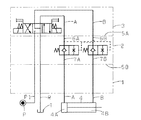
図1および図2において、1はマニホールドで、弁2と電磁切換弁3とを積層配設している。電磁切換弁3はシリンダ4のヘツド室4Aとロツド室4Bとに接続した2個の負荷流路A、Bを圧力源Pに接続した供給流路P1と低圧側Tに接続した排出流路Rとに切換連通して設けている。
【0008】
5は弁2の弁本体で、マニホールド1上に電磁切換弁3との間に積層配設を自在に直方体形状に設け、供給流路P1と排出流路Rとを縦方向に貫通して上下端面5A、5Bに開口して設けると共に、上端面5Aには電磁切換弁3側の負荷流路A、Bに接続して流体が流通する第1流通路6A、6Bを開口し、下端面5Bにはマニホールド1側の負荷流路A、Bに接続して流体が流通する第2流通路7A、7Bを開口している。8は貫通孔で、弁本体5に貫通して上下端面5A、5Bと直交する両側面5C、5Dに開口して設け、貫通孔8には第1流通路6A、6Bと第2流通路7A、7Bとを軸方向に間隙を有して開口して設けている。
【0009】
9A、9Bは円筒形状のスリーブ部材で、貫通孔8に両側面5C、5Dの開口からそれぞれ挿入して設け、貫通孔8の両側面5C、5Dの開口を着脱自在に閉塞する蓋部材20A、20Bで軸方向へ位置決め固定して弁本体5の一部を構成している。スリーブ部材9A、9Bには小径孔10A、10Bと小径孔10A、10Bより大径の大径孔11A、11Bを連設して軸方向に貫通して両端面に開口して設けている。小径孔10A、10Bはスリーブ部材9A、9B一端面への開口より第1流通路6A、6Bに連通して設け、大径孔11A、11Bはスリーブ部材9A、9Bに径方向へ穿設の流路12A、12Bを介して第2流通路7A、7Bに連通している。
【0010】
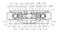
13A、13Bは第1弁座で、小径孔10A、10Bのスリーブ部材9A、9B一端面への開口稜部に形成して設けている。14A、14Bは第2弁座で、小径孔10A、10Bと大径孔11A、11Bとの連設段部に形成して設けている。15A、15Bは弁体で、大径孔11A、11Bへ移動自在に収装し、第2弁座14A、14Bに着座して設けている。16A、16Bはばねで、弁体15A、15B背部に収装し、弁体15A、15Bを第2弁座14A、14Bへの着座方向に付勢して設けている。17はパイロツトピストンで、貫通孔8の軸方向中央へ移動自在に収装して設け、その両端面よりロツド部17A、17Bを突設し、ロツド部17A、17Bは小径孔10A、10Bをこの内周面と径方向に間隙を有して延在し、ロツド部17A、17Bの延在した端部を弁体15A、15B頭部と当接自在に対向して設けている。
【0011】
パイロツトピストン17はロツド部17A、17Bの根元にテーパー形状の弁部18A、18Bを形成して設け、第1流通路6A若しくは6Bを流通する流体がパイロツト流体としてこの圧力が端面に作用することで図2の右方向若しくは左方向へ移動して弁体15B若しくは15Aを第2弁座14B若しくは14Aからの離座方向に押圧すると共に、弁部18B若しくは18Aを第1弁座13B若しくは13Aに着座自在に設けている。19A、19Bは流体を絞り制御する絞り孔で、小径孔10A、10Bと第1流通路6A、6B間を第1弁座13A、13Bを介する連通と並列に連通するようスリーブ部材9A、9Bに径方向へ穿設している。
【0012】
次にかかる構成の作動を説明する。
図1および図2はシリンダ4の停止状態を示し、電磁切換弁3は中立位置に位置して負荷流路A、Bを排出流路Rに連通し供給流路P1を遮断し、弁2は弁体15A、15Bがばね16A、16B力により第2弁座14A、14Bに着座してシリンダ4側から電磁切換弁3側への流体の流れを阻止し、シリンダ4は左端に停止している。
【0013】
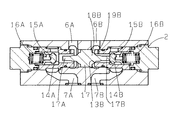
図1の状態より、電磁切換弁3を左位置に切換操作すると、負荷流路Aを供給流路P1に切換連通し負荷流路Bを排出流路Rに切換連通する。圧力源Pから供給流路P1に供給した流体は負荷流路Aより図3に示す如き弁2の第1流通路6Aを流れて弁体15A頭部に作用して弁体15Aをばね16A力に抗して第2弁座14Aから離座して自由流れで第2流通路7Aに流れてシリンダ4のヘツド室4Aに導入する。また、第1流通路6Aを流れた流体はパイロツト流体としてパイロツトピストン17のロツド部17Aを突設した端面に作用し、パイロツトピストン17はパイロツト流体の圧力の作用で右方向に移動してロツド部17Bが弁体15B頭部に当接し、弁体15Bをばね16B力に抗して押圧して第2弁座14Bから離座すると共に、弁部18Bが第1弁座13Bに着座する。シリンダ4のロツド室4Bから負荷流路Bに導出した流体は第2流通路7Bより絞り孔19Bで絞り制御されて第1流通路6Bを流れて排出流路Rより低圧側Tに排出され、シリンダ4は図1の右方向へメータアウト回路で速度制御して作動する。
【0014】
シリンダ4が図1の右端まで作動すると、電磁切換弁3を中立位置に復帰操作する。これにより、第1流通路6A、6Bが負荷流路A、Bより排出流路Rに切換連通され、パイロツトピストン17にパイロツト流体が作用しなくなり、弁体15A、15Bはばね16A、16B力により第2弁座14A、14Bに着座すると共に、パイロツトピストン17はばね16B力により図3の左方向に移動して弁部18Bが第1弁座13Bから離座する。シリンダ4は右端で停止する。
【0015】
この状態より、電磁切換弁3を右位置に切換操作すると、負荷流路Aを排出流路Rに切換連通し負荷流路Bを供給流路P1に切換連通する。供給流路P1の流体は負荷流路Bを流れて弁体15Bを第2弁座14Bから離座して自由流れで第2流通路7Bに流れてシリンダ4のロツド室4Bに導入する。また、パイロツトピストン17は第1流通路6Bを流れる流体がパイロツト流体として作用し、前述と逆に図2の左方向に移動して弁体15Aを第2弁座14Aから離座すると共に、弁部18Aが第1弁座13Aに着座する。シリンダ4のヘツド室4Aから導出した流体は第2流通路7Aより絞り孔19Aで絞り制御されて第1流通路6Aを流れて排出流路Rより低圧側Tに排出され、シリンダ4は右端より図1の左方向へメータアウト回路で速度制御して作動する。そして、シリンダ4が左端まで作動すると、電磁切換弁3を中立位置に復帰操作し、弁2は弁体15A、15Bが第2弁座14A、14Bに着座すると共に、パイロツトピストン17は右方向に移動して弁部18Aが第1弁座13Aから離座する。シリンダ4は図1に示す左端で停止する。
【0016】
かかる作動で、弁2は、パイロツトピストン17にパイロツト流体が作用していない場合には弁体15A、15Bが第2弁座14A、14Bに着座して第2流通路7A、7Bから第1流通路6A、6Bへの流体の流れを阻止すると共に、パイロツトピストン17にパイロツト流体が作用した場合には弁体15A若しくは15Bを第2弁座14A若しくは14Bから離座して弁部18A若しくは18Bを第1弁座13A若しくは13Bに着座して第2流通路7A若しくは7Bからの流体を絞り孔19A若しくは19Bで絞り制御して第1流通路6A若しくは6Bに流すため、図5に示す従来の装置における一方向絞り弁26A、26Bとパイロツト操作逆止め弁24とを負荷流路A、Bに直列に配設した場合と同等の機能を単一の弁2で得ることができて、装置全体の小型化を図ることができる。また、弁2はパイロツトピストン17に弁部18A、18Bを形成して設け、移動する部材として弁体15A、15B、パイロツトピストン17で良く、既存のパイロツト操作逆止め弁と比較して移動する部材を増加することなくできて、構成の複雑化を良好に抑制することができる。さらにまた、蓋部材20A、20Bを取り外して絞り孔19A、19Bの径が異なる他のスリーブ部材9A、9Bに交換することで、絞り開度を適宜変更することができる。
【0017】
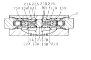
図4は本発明の他実施例を示し、一実施例と同一個所には同符号を付して説明を省略し、異なる個所についてのみ説明する。
流体を絞り制御する絞り孔21A、21Bは、パイロツトピストン22にその一端を小径孔10A、10B内に延在するロツド部22A、22B外周面に開口すると共に、その他端を弁部23A、23Bの常に第1流通路6A、6Bに面する根元に開口して設け、小径孔10A、10Bと第1流通路6A、6B間を第1弁座13A、13Bを介する連通と並列に連通している。そして、一実施例と同様の作動で、一実施例と同様に装置全体の小型化を図ることができると共に、弁2は構成の複雑化を良好に抑制することができる。
【0018】
尚、本実施例では、負荷流路A、Bに対応して弁体15A、15Bを2個設けてシリンダ4の右方向および左方向への作動でともにメータアウト回路で速度制御したが、一方向への作動のみをメータアウト回路で速度制御する場合には必要な負荷流路A若しくはBに対応して1個の弁体を設ければ良いことは勿論である。
【0019】
【発明の効果】
このように、本発明は、流体の一方向への流れを自由流れとすると共に他方向への流れを絞り制御する一方向絞り弁と、パイロツト操作により開閉作動するパイロツト操作逆止め弁とを直列に配設した機能を備えた流体制御装置において、弁本体内に小径孔と小径孔より大径の大径孔を連設し、小径孔には第1弁座を介して流体が流通する第1流通路を連通すると共に大径孔には流体が流通する第2流通路を連通して設け、小径孔と大径孔の連設段部に第2弁座を形成して設け、第2弁座に着座する弁体を大径孔へ移動自在に収装して設け、パイロツト流体の圧力の作用により弁体を第2弁座からの離座方向に押圧するパイロツトピストンを弁体と対向して移動自在に設け、パイロツトピストンは小径孔の内周面と径方向に間隙を有してロツド部を弁体と当接自在に端面より延在し、パイロツトピストンには弁体の離座方向への押圧により第1弁座に着座する弁部をロツド部の根元にテーパー形状に形成して設け、小径孔と第1流通路間を第1弁座を介する連通と並列に流体を絞り制御する絞り孔で連通し、絞り孔を弁本体若しくはパイロツトピストンに設けているため、流体の一方向への流れを自由流れとすると共に他方向への流れを絞り制御する一方向絞り弁とパイロツト操作により開閉作動するパイロツト操作逆止め弁とを直列に配設した場合と同等の機能を単一の弁で得ることができて、装置全体の小形化を図ることができる。
また、弁はパイロツトピストンのロツド部根元にテーパー形状の弁部を形成して設け、移動する部材として弁体、パイロツトピストンで良く、既存のパイロツト操作逆止め弁と比較して移動する部材を増加することなくできて、構成の複雑化を良好に抑制することができる効果を有する。
【図面の簡単な説明】
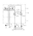
【図1】本発明の一実施例を示した流体制御装置の回路図である。
【図2】一実施例の要部を示した弁の縦断面図である。
【図3】図2の作動状態を示した縦断面図である。
【図4】他実施例を示した弁の縦断面図である。
【図5】従来例を示した流体制御装置の回路図である。
【符号の説明】
2弁
5弁本体
6A、6B第1流通路
7A、7B第2流通路
10A、10B小径孔
11A、11B大径孔
13A、13B第1弁座
14A、14B第2弁座
15A、15B弁体
17、22パイロツトピストン
18A、18B、23A、23B弁部
19A、19B、21A、21B絞り孔[0001]
[Industrial application fields]
In the present invention, a one-way throttle valve that controls the flow in one direction of the fluid while restricting the flow in one direction of the fluid and a pilot operation check valve that opens and closes by a pilot operation are arranged in series. The present invention relates to a fluid control device having a function.
[0002]
[Prior art]
Conventionally, there is such a fluid control apparatus as shown in FIG. In this system, a pilot
[0003]
In the state shown in FIG. 5, the electromagnetic switching valve 3 is located in the neutral position, and the pilot
[0004]
[Problems to be solved by the invention]
However, in the conventional configuration, the one-
The present invention solves such a problem, and a one-way throttle valve for restricting the flow in one direction of the fluid and controlling the flow in the other direction and a pilot operation non-return operation that opens and closes by a pilot operation. The present invention provides a fluid control device in which a function equivalent to that in the case where valves are arranged in series can be obtained with a single valve, and the entire device is reduced in size.
[0005]
[Means for Solving the Problems]
For this reason, the present invention is arranged in series with a one-way throttle valve that restricts the flow in one direction of the fluid and controls the flow in the other direction, and a pilot check valve that opens and closes by a pilot operation. In the fluid control apparatus having the provided function, a first flow in which a small-diameter hole and a large-diameter hole larger in diameter than the small-diameter hole are continuously provided in the valve body, and the fluid circulates through the first valve seat in the small-diameter hole. And a second flow passage through which the fluid flows, and a second valve seat formed on the connecting step portion of the small diameter hole and the large diameter hole. A valve body seated on the valve body is slidably disposed in the large-diameter hole, and a pilot piston that presses the valve body in the direction away from the second valve seat by the action of the pressure of the pilot fluid is opposed to the valve body. provided movably, pilot piston with a gap on the inner circumferential surface in the radial direction of the small-diameter hole rod portion Extending from the valve body and the abutting freely end surface, provided to form a valve portion to be seated on the first valve seat by the pressure of the pilot piston to separating direction of the valve body is tapered at the base of the rod portion, The small-diameter hole and the first flow passage communicate with each other via a throttle hole that controls the fluid in parallel with the communication via the first valve seat , and the throttle hole is provided in the valve body . In this case, the throttle hole may be provided in the pilot piston instead of the valve body.
[0006]
[Action]
In such a configuration of the present invention, when the pressure of the pilot fluid does not act on the pilot piston, when the fluid flows in from the first flow passage, the fluid flows through the first valve seat and the small diameter hole, and the valve body is moved to the second valve seat. When the fluid flows into the second flow path from the large-diameter hole, the valve body is seated on the second valve seat and the second valve seat is opened. The flow to the 1st flow path side is blocked. Further, when the pressure of the pilot fluid acts on the pilot piston, the pilot piston presses the valve body by the action of the pressure of the pilot fluid to separate from the second valve seat, and the valve portion is seated on the first valve seat, The fluid flowing in from the second flow passage flows from the large-diameter hole through the second valve seat and the small-diameter hole, and is controlled by the throttle hole to flow to the first flow passage. For this reason, if the pressure of the pilot fluid is not acting on the pilot piston, the fluid flows freely from the first flow path to the second flow path and prevents the flow of fluid from the second flow path to the first flow path. When the pressure of the pilot fluid acts on the pilot piston, the fluid can be controlled to flow from the second flow passage to the first flow passage, so that the flow in one direction of the fluid is a free flow and the flow in the other direction. A single valve can provide the same function as a one-way throttle valve that controls the flow and a pilot operated check valve that opens and closes by pilot operation. Can be achieved.
[0007]
【Example】
Hereinafter, an embodiment of the present invention will be described with reference to the drawings. In addition, the same code | symbol is attached | subjected to the same location as a prior art example.
In FIG. 1 and FIG. 2, reference numeral 1 denotes a manifold, in which a
[0008]
[0009]
9A and 9B are cylindrical sleeve members, which are provided by being inserted into the through-
[0010]
13A and 13B are 1st valve seats, and are formed and formed in the opening ridge part to
[0011]
The pilot piston 17 is provided by forming tapered
[0012]
Next, the operation of this configuration will be described.
1 and 2 show a stopped state of the
[0013]
When the electromagnetic switching valve 3 is switched to the left position from the state of FIG. 1, the load flow path A is switched to the supply flow path P1 and the load flow path B is switched to the discharge flow path R. The fluid supplied from the pressure source P to the supply flow path P1 flows from the load flow path A through the
[0014]
When the
[0015]
When the electromagnetic switching valve 3 is switched to the right position from this state, the load channel A is switched to the discharge channel R and the load channel B is switched to the supply channel P1. The fluid in the supply flow path P1 flows through the load flow path B, leaves the
[0016]
With this operation, when the pilot fluid is not acting on the pilot piston 17, the
[0017]
FIG. 4 shows another embodiment of the present invention. The same reference numerals are given to the same portions as those of the first embodiment, the description thereof is omitted, and only different portions will be described.
The throttle holes 21A and 21B for throttle-controlling the fluid open one end of the
[0018]
In this embodiment, two
[0019]
【The invention's effect】
As described above, the present invention provides a series of a one-way throttle valve for controlling the flow in one direction of the fluid to be a free flow and controlling the flow in the other direction, and a pilot operation check valve that opens and closes by a pilot operation. In the fluid control device having the function disposed in the valve body, a small-diameter hole and a large-diameter hole larger in diameter than the small-diameter hole are continuously provided in the valve body, and fluid flows through the small-diameter hole via the first valve seat. The second flow passage is provided in communication with the first flow passage and the fluid is circulated in the large-diameter hole, and the second valve seat is provided in the continuous step portion of the small-diameter hole and the large-diameter hole. A valve body seated on the valve seat is slidably disposed in the large-diameter hole, and a pilot piston that presses the valve body in the direction away from the second valve seat by the action of the pressure of the pilot fluid faces the valve body. and provided movably, pilot piston Rotsu with a gap on the inner circumferential surface in the radial direction of the small diameter hole Parts extending from the valve body and the abutting freely end surface and to form a valve portion to be seated on the first valve seat by the pressure of the pilot piston to separating direction of the valve body is tapered at the base of the rod portion The small-diameter hole and the first flow passage are communicated by a throttle hole that controls the fluid in parallel with the communication through the first valve seat , and the throttle hole is provided in the valve body or the pilot piston, so that one direction of the fluid A one-way throttle valve that throttles and controls the flow in the other direction and a pilot operation check valve that opens and closes by pilot operation are provided in a single function. It can be obtained with a valve, and the overall size of the apparatus can be reduced.
Also, the valve is provided with a tapered valve at the base of the rod part of the pilot piston, and the valve body and pilot piston may be used as the moving member, and the number of moving members is increased compared to existing pilot operation check valves. This has the effect that the complication of the configuration can be satisfactorily suppressed.
[Brief description of the drawings]
FIG. 1 is a circuit diagram of a fluid control apparatus showing an embodiment of the present invention.
FIG. 2 is a longitudinal sectional view of a valve showing the main part of one embodiment.
FIG. 3 is a longitudinal sectional view showing the operating state of FIG. 2;
FIG. 4 is a longitudinal sectional view of a valve showing another embodiment.
FIG. 5 is a circuit diagram of a fluid control apparatus showing a conventional example.
[Explanation of symbols]
2
Claims (2)
Priority Applications (1)
| Application Number | Priority Date | Filing Date | Title |
|---|---|---|---|
| JP26169094A JP3634412B2 (en) | 1994-09-30 | 1994-09-30 | Fluid control device |
Applications Claiming Priority (1)
| Application Number | Priority Date | Filing Date | Title |
|---|---|---|---|
| JP26169094A JP3634412B2 (en) | 1994-09-30 | 1994-09-30 | Fluid control device |
Publications (2)
| Publication Number | Publication Date |
|---|---|
| JPH08105406A JPH08105406A (en) | 1996-04-23 |
| JP3634412B2 true JP3634412B2 (en) | 2005-03-30 |
Family
ID=17365367
Family Applications (1)
| Application Number | Title | Priority Date | Filing Date |
|---|---|---|---|
| JP26169094A Expired - Fee Related JP3634412B2 (en) | 1994-09-30 | 1994-09-30 | Fluid control device |
Country Status (1)
| Country | Link |
|---|---|
| JP (1) | JP3634412B2 (en) |
Families Citing this family (2)
| Publication number | Priority date | Publication date | Assignee | Title |
|---|---|---|---|---|
| JP2006105227A (en) * | 2004-10-04 | 2006-04-20 | Kayaba Ind Co Ltd | Operate check valve, hydraulic drive unit |
| WO2014069435A1 (en) * | 2012-11-05 | 2014-05-08 | カヤバ工業株式会社 | Cylinder control device |
-
1994
- 1994-09-30 JP JP26169094A patent/JP3634412B2/en not_active Expired - Fee Related
Also Published As
| Publication number | Publication date |
|---|---|
| JPH08105406A (en) | 1996-04-23 |
Similar Documents
| Publication | Publication Date | Title |
|---|---|---|
| EP0869418B1 (en) | Pressure regulating valve mounted in base-mounted transfer valve | |
| JPH0583405U (en) | Control valve with pressure compensation valve | |
| JPH11218253A (en) | Proportional solenoid type direction throttle valve | |
| JP3634412B2 (en) | Fluid control device | |
| JP2006017273A (en) | Spool valve | |
| US3266520A (en) | Hydraulic valves | |
| JPH06229402A (en) | Flow rate direction control valve device | |
| JP3714726B2 (en) | Pilot operated check valve | |
| JPS6021590Y2 (en) | Pilot operated directional valve | |
| JP2020133695A (en) | Solenoid valve and work machine | |
| JPH0650302A (en) | Control valve device | |
| JP3574171B2 (en) | Valve device | |
| JPS6123985Y2 (en) | ||
| JP3793666B2 (en) | Hydraulic control device | |
| JPS6319405A (en) | Flow control valve | |
| JPH0249361Y2 (en) | ||
| JP2954790B2 (en) | Control device for transmission operation actuator | |
| JPH0640322Y2 (en) | Liquid control device | |
| JPS62194008A (en) | Fluid control device | |
| JPH0375762B2 (en) | ||
| JPH0438135Y2 (en) | ||
| JPS5824699Y2 (en) | Pilot operated switching valve | |
| JP4504144B2 (en) | On-off valve and hydraulic device for injection control using the on-off valve | |
| JP2571246Y2 (en) | Pilot operated check valve | |
| JPS62194007A (en) | Fluid control device |
Legal Events
| Date | Code | Title | Description |
|---|---|---|---|
| A977 | Report on retrieval |
Free format text: JAPANESE INTERMEDIATE CODE: A971007 Effective date: 20040730 |
|
| A131 | Notification of reasons for refusal |
Free format text: JAPANESE INTERMEDIATE CODE: A131 Effective date: 20040810 |
|
| A521 | Written amendment |
Free format text: JAPANESE INTERMEDIATE CODE: A523 Effective date: 20040924 |
|
| TRDD | Decision of grant or rejection written | ||
| A01 | Written decision to grant a patent or to grant a registration (utility model) |
Free format text: JAPANESE INTERMEDIATE CODE: A01 Effective date: 20041221 |
|
| A61 | First payment of annual fees (during grant procedure) |
Free format text: JAPANESE INTERMEDIATE CODE: A61 Effective date: 20041224 |
|
| R150 | Certificate of patent or registration of utility model |
Free format text: JAPANESE INTERMEDIATE CODE: R150 |
|
| FPAY | Renewal fee payment (event date is renewal date of database) |
Free format text: PAYMENT UNTIL: 20090107 Year of fee payment: 4 |
|
| FPAY | Renewal fee payment (event date is renewal date of database) |
Free format text: PAYMENT UNTIL: 20100107 Year of fee payment: 5 |
|
| FPAY | Renewal fee payment (event date is renewal date of database) |
Free format text: PAYMENT UNTIL: 20100107 Year of fee payment: 5 |
|
| FPAY | Renewal fee payment (event date is renewal date of database) |
Free format text: PAYMENT UNTIL: 20110107 Year of fee payment: 6 |
|
| FPAY | Renewal fee payment (event date is renewal date of database) |
Free format text: PAYMENT UNTIL: 20120107 Year of fee payment: 7 |
|
| LAPS | Cancellation because of no payment of annual fees |