JP3633552B2 - Data transfer method, data transfer system, terminal adapter, and control program for the terminal adapter - Google Patents
Data transfer method, data transfer system, terminal adapter, and control program for the terminal adapter Download PDFInfo
- Publication number
- JP3633552B2 JP3633552B2 JP2001384841A JP2001384841A JP3633552B2 JP 3633552 B2 JP3633552 B2 JP 3633552B2 JP 2001384841 A JP2001384841 A JP 2001384841A JP 2001384841 A JP2001384841 A JP 2001384841A JP 3633552 B2 JP3633552 B2 JP 3633552B2
- Authority
- JP
- Japan
- Prior art keywords
- data
- peripheral device
- time width
- terminal
- prompting
- Prior art date
- Legal status (The legal status is an assumption and is not a legal conclusion. Google has not performed a legal analysis and makes no representation as to the accuracy of the status listed.)
- Expired - Fee Related
Links
- 238000012546 transfer Methods 0.000 title claims description 85
- 238000000034 method Methods 0.000 title claims description 11
- 230000002093 peripheral effect Effects 0.000 claims description 69
- 238000004891 communication Methods 0.000 claims description 35
- 238000004573 interface analysis Methods 0.000 claims description 17
- 230000005540 biological transmission Effects 0.000 claims description 12
- 238000012545 processing Methods 0.000 claims description 10
- 238000004458 analytical method Methods 0.000 claims description 6
- 238000010586 diagram Methods 0.000 description 19
- 230000004308 accommodation Effects 0.000 description 5
- 230000006870 function Effects 0.000 description 4
- 238000001994 activation Methods 0.000 description 1
- 238000012790 confirmation Methods 0.000 description 1
- 238000013461 design Methods 0.000 description 1
- 230000000694 effects Effects 0.000 description 1
- 238000000605 extraction Methods 0.000 description 1
Images


Landscapes
- Data Exchanges In Wide-Area Networks (AREA)
- Communication Control (AREA)
- Telephonic Communication Services (AREA)
Description
【0001】
【発明の属する技術分野】
この発明は、データ転送方法、データ転送システム、ターミナルアダプタ、及び該ターミナルアダプタの制御プログラムに係り、特に、ユーザ端末に例えばUSB(ユニバーサル・シリアル・バス)規格の周辺機器が多数接続される場合に用いて好適なデータ転送方法、データ転送システム、ターミナルアダプタ、及び該ターミナルアダプタの制御プログラムに関する。
【0002】
【従来の技術】
従来のデータ転送システムでは、ユーザ端末に例えばマウス、キーボード、スキャナ、ディジタルカメラなどの周辺機器が接続される場合、それぞれ専用のケーブルを介して接続される。ところが、近年では、これらの周辺機器にUSB規格のインタフェースが設けられ、USB規格のケーブル(以下、「USBケーブル」という)を介してユーザ端末に接続されることが多くなっている。
【0003】
この種のデータ転送システムは、従来では例えば図10に示すように、ユーザ端末1と、ディジタルカメラ2と、スキャナ3と、ターミナルアダプタ4と、サーバ5とからなっている。ディジタルカメラ2はUSBケーブル2aを介してユーザ端末1のUSBポートに接続され、スキャナ3がUSBケーブル3aを介してユーザ端末1に接続されている。また、ユーザ端末1には、ターミナルアダプタ4が接続され、同ターミナルアダプタ4はISDN回線NWを介してサーバ5に接続されている。
【0004】
このデータ転送システムでは、ディジタルカメラ2のデータAは、USBケーブル2aを介してユーザ端末1に送出され、同ユーザ端末1からターミナルアダプタ4及びISDN回線NWを介してサーバ5に転送される。同様に、スキャナ3のデータBは、USBケーブル3aを介してユーザ端末1に送出され、る。ユーザ端末1に蓄積された前記データは、ユーザ端末1からターミナルアダプタ4およびISDN回線NWを介してサーバ5に転送をおこなったり、ディジタルカメラ2やスキャナ3とは独立して、ターミナルアダプタ4はインターネット等に接続し、データ送受信に使用される。この場合、ユーザ端末1から例えば1msに1回ずつSOF(Start of Frame)パケットが発生し、ディジタルカメラ2のデータA,スキャナ3のデータB及びターミナルアダプタ4のデータCは、この1msの時間幅のフレーム内に同データA,B,Cのデータ量に応じた時間幅に分割されてUSBケーブルを介して転送される。
【0005】
【発明が解決しようとする課題】
しかしながら、上記従来のデータ転送システムでは、次のような問題点があった。
すなわち、ユーザ端末1に接続される周辺機器が例えばディジタルカメラ2とターミナルアダプタ4のみの場合、同ディジタルカメラ2とターミナルアダプタ4とがユーザ端末1のUSB規格の1フレームの時間幅(すなわち、1ms)を占有できるので、例えばISDN回線NWを介して最大の回線速度128kbpsで通信を行うために十分な転送速度が確保される。ところが、近年では、ディジタルカメラ2やスキャナ3の他、例えば、マウスやキーボードなどの他、諸々の周辺機器にもUSB規格のインタフェースが設けられてユーザ端末1のUSBポートに同時に接続されることが多くなり、1フレーム内で各周辺機器に割り当てられる時間幅が十分に確保されなくなるという問題点がある。
【0006】
この場合、各周辺機器では、ユーザ端末1に他の周辺機器が接続されていることを検出する機能がないため、ISDN回線NWの回線速度とデータA,B,Cの転送速度との整合が取れない状態が検出されなかった。また、ターミナルアダプタ4も、ユーザ端末1とISDN回線NWとの間のインタフェースとしての働きを行うのみであり、このような状態を検出することができなかった。このため、データA,B,Cの転送速度が十分に確保されない場合でも、回線速度が128kbpsで設定され、ISDN回線NWにおける例えば2チャネル分の料金がユーザに課金されることがあるという問題点があった。また、ユーザ端末1に多数の周辺機器が接続された場合、同ユーザ端末1に対する負荷が重くなり、データ転送システムが不安定になることがあるという問題点があった。
【0007】
これらの問題点を改善するものとして、例えば、特開2000−48186号公報に記載されたデータ転送システム(同公報では、画像処理システムとして説明されている)が提案されている。同公報に記載されたデータ転送システムでは、1つのパーソナルコンピュータ(以下、「パソコン」という)がUSB規格の周辺機器に対するユーザ端末として用いられ、USBホスト(ユーザ端末)が主導権であるUSBは、同パソコンによって各周辺機器にUSB規格で割り当てられる時間幅が比較的容易に調整される。ところが、パソコンが古い機種や低機能の機種の場合、各周辺機器に割り当てられる時間幅を調整する機能がなく、前記問題点に対処できないことがあるという問題点があった。
【0008】
この発明は、上述の事情に鑑みてなされたもので、十分な転送速度が確保され、安定したデータ転送を行うデータ転送システム、該システムに用いられるターミナルアダプタ、及びデータ転送方法を提供することを目的としている。
【0009】
【課題を解決するための手段】
上記課題を解決するために、請求項1記載の発明は、複数の周辺機器が、1対1にあてがわれたUSB(ユニバーサル・シリアル・バス)ケーブルを介して、それぞれ接続され、前記各周辺機器から対応する前記USBケーブルを介して入出力されるデータを、データ量に応じて割り当てた割当時間幅で所定のフレーム時間幅のフレームごとに時分割多重して処理を行うユーザ端末と、別のUSBケーブルを介して前記ユーザ端末に接続され、前記別のUSBケーブルを介して入出力される送受信データを、所定の回線速度が設定されている通信回線へ送出するターミナルアダプタと、前記通信回線を介して送受信データを送受信する受信端末とを備えてなるデータ転送システムに係り、前記ターミナルアダプタは、前記各周辺機器のデータ量に応じて割り当てられた割当時間幅から前記各データの転送速度を求め、これらの転送速度の合計が前記通信回線に設定されている回線速度に整合しないとき、前記回線速度の変更を促すための情報、又は前記各周辺機器の数の変更を促すための情報をユーザに伝達する構成にされていることを特徴としている。
【0010】
請求項2記載の発明は、請求項1記載のデータ転送システムに係り、前記ターミナルアダプタは、前記各周辺機器に割り当てられた割当時間幅、及び前記各割当時間幅におけるデータ量に基づいて各データの転送速度を求め、これらの転送速度の合計が前記通信回線に設定されている回線速度に整合しないとき、前記回線速度の変更を促すための情報、又は前記各周辺機器の数の変更を促すための情報を生成する制御部と、前記回線速度の変更を促すための情報、又は前記各周辺機器の数の変更を促すための情報をユーザに対して表示する表示部とを備えてなることを特徴としている。
【0011】
請求項3記載の発明は、1対1にあてがわれたUSB(ユニバーサル・シリアル・バス)ケーブルを介して、複数の周辺機器と共にユーザ端末に接続され、前記ユーザ端末から入出力される通信相手先への送受信のデータをデータ量に応じて割り当てられた割当時間幅で所定のフレーム時間幅のフレームごとに時分割多重したフレーム列を、所定の回線速度が設定されている通信回線へ送出するターミナルアダプタに係り、前記各周辺機器のデータ量に応じて割り当てられた割当時間幅から前記各データの転送速度を求め、これらの転送速度の合計が前記通信回線に設定されている回線速度に整合しないとき、前記回線速度の変更を促すための情報、又は前記各周辺機器の数の変更を促すための情報をユーザに伝達する構成にされていることを特徴としている。
【0012】
請求項4記載の発明は、請求項3記載のターミナルアダプタに係り、前記ユーザ端末から供給される周辺機器情報に基づいて、データの転送方式を少なくとも含む前記各周辺機器の内容を解析して解析結果を生成するインタフェース解析部を備えていることを特徴としている。
【0013】
請求項5記載の発明は、請求項4記載のターミナルアダプタに係り、前記インタフェース解析部は、前記各周辺機器のトークンのパケットを受信して解析する構成になされていることを特徴としている。
【0014】
請求項6記載の発明は、請求項4又は5記載のターミナルアダプタに係り、前記インタフェース解析部の解析結果に基づき、前記ユーザ端末に接続されている前記周辺機器の数、及び、各周辺機器の転送モードや占有バンド予測値を含む管理テーブルを生成して、前記各周辺機器を管理する制御部を備えてなることを特徴としている。
【0015】
請求項7記載の発明は、1対1にあてがわれたUSB(ユニバーサル・シリアル・バス)ケーブルを介して、複数の周辺機器と共にユーザ端末に接続され、前記ユーザ端末から入出力される通信相手先への送受信データをデータ量に応じて割り当てられた割当時間幅で所定のフレーム時間幅のフレームごとに時分割多重したフレーム列を、所定の回線速度が設定されている通信回線へ送出するターミナルアダプタに係り、前記各周辺機器に割り当てられた割当時間幅、及び前記各割当時間幅におけるデータ量に基づいて各データの転送速度を求め、これらの転送速度の合計が前記通信回線に設定されている回線速度に整合しないとき、前記回線速度の変更を促すための情報、又は前記各周辺機器の数の変更を促すための情報を生成する制御部と、前記回線速度の変更を促すための情報、又は前記各周辺機器の数の変更を促すための情報をユーザに対して表示する表示部とを備えてなることを特徴としている。
【0016】
請求項8記載の発明は、データ転送方法に係り、複数の周辺機器が、1対1にあてがわれたUSB(ユニバーサル・シリアル・バス)ケーブルを介して、それぞれ接続され、前記各周辺機器から対応する前記USBケーブルを介して入力されるデータを、データ量に応じて割り当てた割当時間幅で所定のフレーム時間幅のフレームごとに時分割多重してデータとして入出力するユーザ端末と、別のUSBケーブルを介して前記ユーザ端末に接続され、前記別のUSBケーブルを介して入出力される前記フレーム列を、所定の回線速度が設定されている通信回線へ送出するターミナルアダプタと、前記通信回線を介して前記データを送受信する端末とを備えてなるデータ転送システムにおいて、前記ターミナルアダプタが、前記各周辺機器のデータ量に応じて割り当てられた割当時間幅から前記各データの転送速度を求め、これらの転送速度の合計が前記通信回線に設定されている回線速度に整合しないとき、前記回線速度の変更を促すための情報、又は前記各周辺機器の数の変更を促すための情報をユーザに伝達することを特徴としている。
【0017】
請求項9記載の発明は、制御プログラムに係り、コンピュータに請求項3又は4記載のターミナルアダプタの機能を実現させる構成とされていることを特徴としている。
【0018】
【発明の実施の形態】
以下、図面を参照して、この発明の実施の形態について説明する。
図1は、この発明の実施形態であるデータ転送システムの構成図である。
この形態のデータ転送システムは、同図に示すように、ユーザ端末11と、ディジタルカメラ12と、スキャナ13と、ターミナルアダプタ20と、通信相手端末30とからなっている。
ユーザ端末11は、例えばパソコンで構成され、USBケーブル12aを介してディジタルカメラ12が接続される共に、USBケーブル13aを介してスキャナ13が接続され、同ディジタルカメラ12及びスキャナ13から同USBケーブル12a,13aを介して入出力されるデータA,Bを、同データA,Bのデータ量に応じて割り当てられた割当時間幅で所定のフレーム時間幅(例えば、1ms)のフレームごとに時分割多重する。
【0019】
ターミナルアダプタ20は、USBケーブル20aを介してユーザ端末11に接続され、同USBケーブル20aを介して入出力される送受信データを所定の回線速度が設定されている通信回線(ISDN回線)NWへ送出すると共に、ディジタルカメラ12及びスキャナ13から入出力されるデータA,Bのデータ量に応じて割り当てられた割当時間幅から各データA,Bの転送速度を求め、これらの転送速度の合計が送受信しているデータ速度に影響し、送受信データがISDN回線NWの回線速度に整合しないとき、同回線速度の変更を促すための情報、又はディジタルカメラ12及びスキャナ13の数の変更を促すための情報をユーザに伝達する。通信相手端末30は、例えばパソコンなどで構成され、ISDN回線NWを介してデータを送受信する。
【0020】
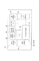
図2は、図1中のターミナルアダプタ20の構成図である。
このターミナルアダプタ20は、同図2に示すように、端末収容部21と、回線収容部22と、インタフェース解析部23と、情報記憶部24と、表示部25と、制御部40とから構成されている。端末収容部21は、ユーザ端末11をUSBケーブル20aを介して収容し、同ユーザ端末11に接続されている周辺機器の種類や仕様などを表す周辺機器情報を出力する。回線収容部22は、通信相手端末30とのインタフェースを提供する。インタフェース解析部23は、端末収容部21から送出される周辺機器情報に基づいてディジタルカメラ12及びスキャナ13の内容(例えば、USBデバイスの数やデータの転送方式)を解析して解析結果を生成する。
【0021】
情報記憶部24は、インタフェース解析部23の解析結果及びターミナルアダプタ20全体のシステムデータを保持する。制御部40は、ターミナルアダプタ20全体の制御を行うと共に、インタフェース解析部23の解析結果に基づき、周辺機器(ディジタルカメラ12及びスキャナ13)の数、ディジタルカメラ12及びスキャナ13に割り当てられた各割当時間幅、及び同各割当時間幅におけるデータ量に基づいて各データA,Bの転送速度を求め、同転送速度の合計が送受信しているデータ速度に影響し、送受信データがISDN回線NWの回線速度に整合しないとき、同回線速度の変更を促すための情報、又はディジタルカメラ12及びスキャナ13の数の変更を促すための情報を生成する。表示部25は、制御部40で生成されたこれらの情報をユーザに対して表示する。
【0022】
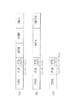
図3は、図2中の制御部40の構成図である。
この制御部40は、図3に示すように、端末収容部I/F(インタフェース)41と、端末制御部42と、情報記憶部I/F43と、時間幅算出部44と、回線収容部I/F45と、プロトコル制御部46と、中央演算処理部47と、メモリ48と、表示部I/F49とから構成されている。端末収容部I/F41は、端末収容部21と端末制御部42との間のインタフェースである。端末制御部42は、所定のプロトコルに基づいて端末収容部I/F41を介して周辺機器や信号線に対する制御を行う。情報記憶部I/F43は、情報記憶部24と中央演算処理部47との間のインタフェースである。
【0023】
時間幅算出部44は、ディジタルカメラ12及びスキャナ13に割り当てられた各割当時間幅、及び同各割当時間幅におけるデータ量に基づいて各データの転送速度を求め、同転送速度の合計を算出する。回線収容部I/F45は、回線収容部22とプロトコル制御部46との間のインタフェースである。プロトコル制御部46は、所定のプロトコルに基づいて回線収容部I/F45を介してISDN回線NWにおける切断/発信などの制御を行う。中央演算処理部47は、制御部40全体を制御すると共に、時間幅算出部44で算出された転送速度の合計と、ISDN回線NWの回線速度(128kbps)とを比較し、同転送速度の合計が128kbpsを下回った場合、同回線速度の低下を促すための情報を生成する。メモリ48は、制御部40動作させるための制御プログラムが記録される。表示部I/F49は、表示部25と中央演算処理部47との間のインタフェースである。
【0024】
図4は、ターミナルアダプタ20の接続時のシーケンスを示す図、図5がUSBデータの流れを示す図、図6はUSBパケットの例を示す図、図7がOUTトークンのシーケンスの例を示す図、図8はINトークンのシーケンスの例を示す図、及び図9が管理テーブルの例を示す図である。
これらの図を参照して、この形態のデータ転送システムにおけるデータ転送方法の処理内容について説明する。
図4に示すように、ユーザ端末11にUSBケーブル20aを介してターミナルアダプタ20が接続されたとき、同ユーザ端末11によって同ターミナルアダプタ20がリセットされる。その後、ユーザ端末11によってターミナルアダプタ20の活性化(Enumeration) 処理が行われ、同ターミナルアダプタ20が同ユーザ端末11にUSBデバイスとして登録される。この場合、USBデバイスがターミナルアダプタ20のみであれば、同ターミナルアダプタ20がユーザ端末11のUSB規格のフレーム時間幅(すなわち、1ms)を占有できるので、ISDN回線NWにてインターネット接続を行う場合、同ISDN回線NWの最大速度128kbpsで通信を行うために十分な転送速度が確保される。
【0025】
ところが、最近では、USBデバイスが豊富に出揃ったため、図1に示すように、USB規格のディジタルカメラ12、USB規格のスキャナ13の他、USB規格の図示しないマウスやキーボードなどがユーザ端末11のUSBポートに同時接続されることが多くなり、これらのUSB規格のデバイスに割り当てられる割当時間幅が十分に確保されなくなることがある。ターミナルアダプタ20は、これらのUSBデバイスがユーザ端末11に接続されて割当時間幅が圧迫されたときに有効になるものである。
【0026】
ユーザ端末11にターミナルアダプタ20がUSBデバイスとして登録された後、図5に示すように、同ユーザ端末11のUSBポートに接続されている他のUSBデバイス(ディジタルカメラ12及びスキャナ13)に対するINトークン(すなわち、USBデバイスからユーザ端末11へデータパケットを送出させるための指示)及びOUTトークン(すなわち、ユーザ端末11からUSBデバイスへデータパケットを送出するための指示)が同ターミナルアダプタ20で監視される。この場合、ターミナルアダプタ20中のインタフェース解析部23が、図6(a)に示すトークンパケットを構成するフィールド“SYNC”(同期信号),“PID|PID/”,“ADDR”,“ENDP”を抽出した後、同フィールド“PID|PID/”に基づいてUSBパケットの種別、同フィールド“ADDR”に基づいてUSBデバイスのアドレス、及び同フィールド“ENDP”に基づいてUSBデバイスが使用しているエンドポイント(すなわち、USBデバイスが保持している元データを図6(b)に示す転送用のデータパケットのサイズに分割するためのもの)を認識し、ユーザ端末11に接続されているUSBデバイスの周辺機器情報を解析する。また、インタフェース解析部23は、トークン受信から図6(c)に示すハンドシェークパケットまでの所要時間、及びトークン受信からSOF(Start Of Frame)や他のトークン受信までの所要時間を解析して制御部40に伝達する。
【0027】
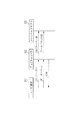
インタフェース解析部23におけるUSBトークンの解析方法は、OUTトークンとINトークンとで異なる。すなわち、図7に示すように、ユーザ端末11からOUTトークンがディジタルカメラ12に向けて送出されたとき、同OUTトークンは、ターミナルアダプタ20にも伝達される。通常のUSBデバイスは、自デバイス宛以外のトークンを受信しないが、この実施形態のターミナルアダプタ20は、端末収容部21及びインタフェース解析部23にて、他のUSBデバイス宛のトークンのパケットを受信して解析する。インタフェース解析部23は、OUTトークンの直後のデータパケットからOUT方向(ユーザ端末11からUSBデバイスへ向かう方向)のデータパケットのレングス(データ長)を解析して制御部40に通知する。制御部40は、図9に示す管理テーブルを情報記憶部24に構築し、ユーザ端末11に接続されているUSBデバイス(ディジタルカメラ12及びスキャナ13)を管理する。この図9中の転送モードの“Bulk”は、大量のデータをまとめて一度に転送するバルク転送モード、“Isochronous”は、動画や音声を扱うために一定の帯域でのデータ転送が保証され、送信側が送り出したタイミングを保持して受信側まで送り届けるモードであるアイソクロナス転送モード、及び“Interrupt”が、例えばマウスやジョイスティックなどのリアルタイム性が要求されるUSBデバイスに用いられ、同USBデバイスからユーザ端末11に周期的に少量のデータを入力するインタラプト転送モードである。
【0028】
また、図8(a),(b)に示すように、ユーザ端末11からINトークンがディジタルカメラ12に対して送出されたとき、同INトークンは、OUTトークンと同様に、ターミナルアダプタ20にも伝達される。ターミナルアダプタ20中のインタフェース解析部23は、INトークンを受信した直後では、ディジタルカメラ12から送信されるデータパケットを受信できないため、データの送受信においてハンドシェークを行う転送の場合には、同図(a)に示すように、INトークンの受信完了からACK(確認通知)の受信までの時間に基づいて同データパケットのサイズを類推する。
【0029】
また、データの送受信においてハンドシェークを行わない転送の場合には、同図(b)に示すように、インタフェース解析部23は、INトークンの受信完了から次のUSB上に流れるパケット(SOFや、他のINトークン、OUTトークンなど)の受信までの時間に基づいてIN方向のデータパケットのサイズを判断して制御部40に通知する。制御部40は、図9に示す管理テーブルを情報記憶部24に構築し、ユーザ端末11に接続されているUSBデバイスを管理する。これにより、制御部40は、ディジタルカメラ12のIN方向及びOUT方向のパケットサイズを類推することができ、同様に、スキャナ13に対するパケットサイズを類推し、このデータ転送システム全体のUSBのパケット占有率を把握する。
【0030】
ターミナルアダプタ20がISDN回線NWに接続される場合、INSネット64では、回線速度64kbpsの2つのデータ伝送チャネル(Bチャネル)が時分割多重化され、回線速度が最大で128kbpsになるため、同ターミナルアダプタ20におけるUSB規格の1フレームの時間幅におけるデータ量から求められる転送速度が128kbps以上である必要がある。このため、制御部40中の時間幅算出部44が、情報記憶部24(図9に示す管理テーブル)に記憶されている他のUSBデバイスの割当時間幅からターミナルアダプタ20の転送速度を算出し、中央演算処理部47が、同転送速度と、ISDN回線NWの回線速度(128kbps)とを比較し、同転送速度が128kbpsを下回った場合、回線速度の設定が適切でないことを表すメッセージを表示部25に送出する。例えば、回線速度がISDN回線NWの128kbpsに設定されていた場合、同回線速度を64kbpsへ下げる要求を表すメッセージを表示部25に送出する。また、転送速度が64kbpsを下回った場合には、中央演算処理部47は、十分な転送速度が確保できないことを表すメッセージを表示部25に送出してユーザに通知する。そして、ユーザが不要なUSBデバイスをユーザ端末11から外すことにより、ユーザが必要とするUSBデバイスに対して1フレーム中の割当時間幅が確保される。
【0031】
以上のように、この実施形態では、USBデバイスのデータの転送速度が確保できない状態で高速の回線を使用することが回避され、ISDN回線NWの使用料を低減できる。また、USBデバイスの増加により、1フレーム中に同USBデバイスに割り当てられる割当時間幅が圧迫された状態で使用を続けると、ユーザ端末11が不安定になる懸念があるが、この実施形態のデータ転送システムにより、割当時間幅が圧迫された状態では、ユーザに対してUSBデバイスの削除を促すので、同ユーザが不要なUSBデバイスを削除することにより、ユーザ端末11の動作が安定する。
【0032】
以上、この発明の実施形態を図面により詳述してきたが、具体的な構成はこの実施形態に限られるものではなく、この発明の要旨を逸脱しない範囲の設計の変更などがあってもこの発明に含まれる。
例えば、実施形態では、通信回線としてISDN回線NWが用いられているが、ローカル・エリア・ネットワーク(LAN)回線を用いても良い。ただし、この場合、回線収容部22及びプロトコル制御部46をLANに対応したものに変更する必要がある。また、ターミナルアダプタ20にADSL(Asymmetric Digital Subscriber Line)やCATV(Cable Television)などに対応したインタフェースを設け、ADSLやCATVを接続しても良い。この場合、ISDN回線とは異なり、回線速度が速くなるので、1フレーム中に割り当てられる時間幅を確保することを目的とした本発明は、非常に有効なものとなる。また、表示部25に送出されるメッセージは、ユーザ端末11に送出して表示しても良い。
【0033】
【発明の効果】
以上説明したように、この発明の構成によれば、周辺機器のデータの転送速度が確保できない状態で高速の回線を使用することを回避でき、回線使用料を低減できる。また、周辺機器の増加により、1フレーム中に割り当てられる割当時間幅が圧迫された状態で使用を続けると、ユーザ端末が不安定になる懸念があるが、この発明のデータ転送システムにより、割当時間幅が圧迫された状態では、ユーザに対して周辺機器の削除を促すので、同ユーザが不要なUSBデバイスを削除することにより、ユーザ端末の動作を安定させることができる。
【図面の簡単な説明】
【図1】この発明の実施形態であるデータ転送システムの構成図である。
【図2】図1中のターミナルアダプタ20の構成図である。
【図3】図2中の制御部40の構成図である。
【図4】ターミナルアダプタ20の接続時のシーケンスを示す図である。
【図5】USBデータの流れを示す図である。
【図6】USBパケットの例を示す図である。
【図7】OUTトークンのシーケンスの例を示す図である。
【図8】INトークンのシーケンスの例を示す図である。
【図9】管理テーブルの例を示す図である。
【図10】従来のデータ転送システムの構成図である。
【符号の説明】
11 ユーザ端末
12 ディジタルカメラ(周辺機器)
13 スキャナ(周辺機器)
20 ターミナルアダプタ
30 通信相手端末
23 インタフェース解析部
40 制御部[0001]
BACKGROUND OF THE INVENTION
The present invention relates to a data transfer method, a data transfer system, a terminal adapter, and a control program for the terminal adapter, and in particular, when a large number of peripheral devices of the USB (Universal Serial Bus) standard, for example, are connected to a user terminal. The present invention relates to a data transfer method suitable for use, a data transfer system, a terminal adapter, and a control program for the terminal adapter.
[0002]
[Prior art]
In a conventional data transfer system, when peripheral devices such as a mouse, a keyboard, a scanner, and a digital camera are connected to a user terminal, they are connected via dedicated cables. In recent years, however, these peripheral devices are provided with USB standard interfaces and are often connected to user terminals via USB standard cables (hereinafter referred to as “USB cables”).
[0003]
Conventionally, this type of data transfer system includes a user terminal 1, a
[0004]
In this data transfer system, data A of the
[0005]
[Problems to be solved by the invention]
However, the conventional data transfer system has the following problems.
That is, when the peripheral devices connected to the user terminal 1 are, for example, only the
[0006]
In this case, since each peripheral device does not have a function of detecting that another peripheral device is connected to the user terminal 1, the line speed of the ISDN line NW and the transfer speed of the data A, B, and C are matched. An unremovable state was not detected. Further, the
[0007]
In order to improve these problems, for example, a data transfer system described in Japanese Patent Application Laid-Open No. 2000-48186 (described in the publication as an image processing system) has been proposed. In the data transfer system described in the publication, a single personal computer (hereinafter referred to as a “personal computer”) is used as a user terminal for a USB standard peripheral device, and a USB host (user terminal) is the initiative of USB. The personal computer can adjust the time width allocated to each peripheral device according to the USB standard relatively easily. However, in the case where the personal computer is an old model or a low-functional model, there is no function for adjusting the time width allocated to each peripheral device, and there is a problem that the above problem may not be dealt with.
[0008]
The present invention has been made in view of the above circumstances, and provides a data transfer system that secures a sufficient transfer speed and performs stable data transfer, a terminal adapter used in the system, and a data transfer method. It is aimed.
[0009]
[Means for Solving the Problems]
In order to solve the above-described problem, the invention according to claim 1 includes a plurality of peripheral devices. 1-to-1 via USB (Universal Serial Bus) cable Connected to each peripheral device Corresponding USB cable A user terminal that performs processing by time-division multiplexing for each frame of a predetermined frame time width with an allocated time width allocated according to the amount of data, Another USB cable Connected to the user terminal via another Data comprising a terminal adapter that sends / receives transmission / reception data input / output via a USB cable to a communication line for which a predetermined line speed is set, and a receiving terminal that transmits / receives transmission / reception data via the communication line. According to a transfer system, the terminal adapter calculates a transfer rate of each data from an allocated time width allocated according to the data amount of each peripheral device, and the total of these transfer rates is set in the communication line. When the line speed does not match, the information for prompting the change of the line speed or the information for prompting the change of the number of each peripheral device is transmitted to the user.
[0010]
According to a second aspect of the present invention, there is provided the data transfer system according to the first aspect, wherein the terminal adapter is configured to allocate each data based on an allocated time width allocated to each peripheral device and a data amount in each allocated time width. When the total of these transfer rates does not match the line speed set for the communication line, information for prompting the change of the line speed or the change of the number of each peripheral device is prompted. And a display unit for displaying information for prompting the change of the line speed or information for prompting the change of the number of each peripheral device to the user. It is characterized by.
[0011]
The invention described in
[0012]
The invention according to
[0013]
According to a fifth aspect of the present invention, there is provided the terminal adapter according to the fourth aspect, wherein the interface analysis unit is configured to receive and analyze a token packet of each peripheral device.
[0014]
The invention according to claim 6 relates to the terminal adapter according to
[0015]
The invention described in claim 7 Via a USB (universal serial bus) cable assigned to one-to-one, Connected to a user terminal together with a plurality of peripheral devices, transmission / reception data to / from a communication partner input / output from / to the user terminal is time-divided for each frame of a predetermined frame time width with an allocated time width assigned according to the data amount The present invention relates to a terminal adapter that sends a multiplexed frame sequence to a communication line for which a predetermined line speed is set, and each allocation time width allocated to each peripheral device and each data amount based on the data amount in each allocation time width. When the data transfer rate is obtained and the sum of these transfer rates does not match the line speed set for the communication line, the information for prompting the change of the line speed or the number of each peripheral device is changed. A control unit that generates information for prompting, and information for prompting a change in the line speed or information for prompting a change in the number of each peripheral device to the user It is characterized by comprising a display unit for displaying.
[0016]
The invention according to claim 8 relates to a data transfer method, wherein a plurality of peripheral devices are provided. 1-to-1 via USB (Universal Serial Bus) cable Connected to each peripheral device Corresponding USB cable A user terminal that inputs and outputs data inputted through time division multiplexing for each frame of a predetermined frame time width with an assigned time width assigned according to the data amount; Another USB cable Connected to the user terminal via Another USB cable A data transfer system comprising: a terminal adapter that transmits the frame sequence input / output via a communication line to a communication line for which a predetermined line speed is set; and a terminal that transmits and receives the data via the communication line The terminal adapter determines the transfer rate of each data from the allocated time width allocated according to the data amount of each peripheral device, and the total of these transfer rates is set to the communication line. When the information does not match, the information for prompting the change of the line speed or the information for prompting the change of the number of each peripheral device is transmitted to the user.
[0017]
The invention described in claim 9 relates to a control program, and is characterized in that a computer is configured to realize the function of the terminal adapter described in
[0018]
DETAILED DESCRIPTION OF THE INVENTION
Embodiments of the present invention will be described below with reference to the drawings.
FIG. 1 is a configuration diagram of a data transfer system according to an embodiment of the present invention.
As shown in the figure, the data transfer system of this form includes a
The
[0019]
The
[0020]
FIG. 2 is a configuration diagram of the
As shown in FIG. 2, the
[0021]
The
[0022]
FIG. 3 is a configuration diagram of the
As shown in FIG. 3, the
[0023]
The time
[0024]
4 is a diagram showing a sequence when the
With reference to these drawings, processing contents of the data transfer method in the data transfer system of this embodiment will be described.
As shown in FIG. 4, when the
[0025]
Recently, however, since a large number of USB devices are available, as shown in FIG. 1, a USB standard
[0026]
After the
[0027]
The method of analyzing the USB token in the
[0028]
8A and 8B, when an IN token is sent from the
[0029]
Further, in the case of transfer without handshaking in data transmission / reception, as shown in FIG. 5B, the
[0030]
When the
[0031]
As described above, in this embodiment, it is possible to avoid using a high-speed line in a state where the data transfer speed of the USB device cannot be secured, and to reduce the usage fee of the ISDN line NW. Further, there is a concern that the
[0032]
The embodiment of the present invention has been described in detail with reference to the drawings. However, the specific configuration is not limited to this embodiment, and the present invention can be changed even if there is a design change without departing from the gist of the present invention. include.
For example, in the embodiment, the ISDN line NW is used as the communication line, but a local area network (LAN) line may be used. However, in this case, it is necessary to change the line accommodating unit 22 and the
[0033]
【The invention's effect】
As described above, according to the configuration of the present invention, it is possible to avoid the use of a high-speed line in a state where the data transfer rate of the peripheral device cannot be secured, and the line usage fee can be reduced. Further, there is a concern that the user terminal may become unstable if the use is continued in a state where the allocated time width allocated in one frame is compressed due to an increase in peripheral devices. In a state where the width is pressed, the user is prompted to delete the peripheral device, so that the user terminal can be stabilized by deleting unnecessary USB devices.
[Brief description of the drawings]
FIG. 1 is a configuration diagram of a data transfer system according to an embodiment of the present invention.
FIG. 2 is a configuration diagram of the
FIG. 3 is a configuration diagram of a
FIG. 4 is a diagram showing a sequence when the
FIG. 5 is a diagram showing a flow of USB data.
FIG. 6 is a diagram illustrating an example of a USB packet.
FIG. 7 is a diagram illustrating an example of a sequence of OUT tokens.
FIG. 8 is a diagram illustrating an example of a sequence of IN tokens.
FIG. 9 is a diagram illustrating an example of a management table.
FIG. 10 is a configuration diagram of a conventional data transfer system.
[Explanation of symbols]
11 User terminal
12 Digital cameras (peripheral devices)
13 Scanner (peripheral equipment)
20 Terminal adapter
30 Communication partner terminal
23 Interface Analysis Unit
40 Control unit
Claims (9)
別のUSBケーブルを介して前記ユーザ端末に接続され、前記別のUSBケーブルを介して入出力される送受信データを、所定の回線速度が設定されている通信回線へ送出するターミナルアダプタと、
前記通信回線を介して送受信データを送受信する受信端末とを備えてなるデータ転送システムであって、
前記ターミナルアダプタは、
前記各周辺機器のデータ量に応じて割り当てられた割当時間幅から前記各データの転送速度を求め、これらの転送速度の合計が前記通信回線に設定されている回線速度に整合しないとき、前記回線速度の変更を促すための情報、又は前記各周辺機器の数の変更を促すための情報をユーザに伝達する構成にされていることを特徴とするデータ転送システム。A plurality of peripheral devices are connected to each other via a USB (Universal Serial Bus) cable assigned one-to-one, and data input / output from / to each peripheral device via the corresponding USB cable A user terminal that performs processing by time-division multiplexing for each frame of a predetermined frame time width with an allocated time width that is allocated according to the data amount;
Via another USB cable is connected to the user terminal, a terminal adapter for sending the received data to be input and output via the another USB cable, to the communication line a given line speed is set,
A data transfer system comprising a receiving terminal for transmitting and receiving transmission / reception data via the communication line,
The terminal adapter is
When the transfer rate of each data is obtained from the allocated time width allocated according to the data amount of each peripheral device, and the total of these transfer rates does not match the line speed set for the communication line, the line A data transfer system configured to transmit information for prompting a change in speed or information for prompting a change in the number of each peripheral device to a user.
前記各周辺機器に割り当てられた割当時間幅、及び前記各割当時間幅におけるデータ量に基づいて各データの転送速度を求め、これらの転送速度の合計が前記通信回線に設定されている回線速度に整合しないとき、前記回線速度の変更を促すための情報、又は前記各周辺機器の数の変更を促すための情報を生成する制御部と、
前記回線速度の変更を促すための情報、又は前記各周辺機器の数の変更を促すための情報をユーザに対して表示する表示部とを備えてなることを特徴とする請求項1記載のデータ転送システム。The terminal adapter is
A transfer rate of each data is determined based on the allocated time width allocated to each peripheral device and the data amount in each allocated time width, and the total of these transfer rates is the line speed set for the communication line. When not matched, a control unit that generates information for prompting a change in the line speed or information for prompting a change in the number of each peripheral device;
The data according to claim 1, further comprising a display unit that displays information for prompting a change in the line speed or information for prompting a change in the number of each peripheral device to a user. Transfer system.
前記各周辺機器のデータ量に応じて割り当てられた割当時間幅から前記各データの転送速度を求め、これらの転送速度の合計が前記通信回線に設定されている回線速度に整合しないとき、前記回線速度の変更を促すための情報、又は前記各周辺機器の数の変更を促すための情報をユーザに伝達する構成にされていることを特徴とするターミナルアダプタ。Connected to a user terminal together with a plurality of peripheral devices via a USB (universal serial bus) cable assigned to one-to-one, and data transmitted / received to / from a communication partner input / output from / to the user terminal A terminal adapter that sends a frame sequence time-division multiplexed for each frame of a predetermined frame time width with an allocated time width allocated according to the amount to a communication line for which a predetermined line speed is set,
When the transfer rate of each data is obtained from the allocated time width allocated according to the data amount of each peripheral device, and the total of these transfer rates does not match the line speed set for the communication line, the line A terminal adapter configured to transmit information for prompting a change in speed or information for prompting a change in the number of each peripheral device to a user.
前記各周辺機器に割り当てられた割当時間幅、及び前記各割当時間幅におけるデータ量に基づいて各データの転送速度を求め、これらの転送速度の合計が前記通信回線に設定されている回線速度に整合しないとき、前記回線速度の変更を促すための情報、又は前記各周辺機器の数の変更を促すための情報を生成する制御部と、
前記回線速度の変更を促すための情報、又は前記各周辺機器の数の変更を促すための情報をユーザに対して表示する表示部とを備えてなることを特徴とするターミナルアダプタ。Sending and receiving data to and from a communication partner connected to a user terminal together with a plurality of peripheral devices via a USB (universal serial bus) cable assigned one-to-one. A frame adapter that is time-division multiplexed for each frame of a predetermined frame time width with an allocated time width allocated according to the above, to a communication line for which a predetermined line speed is set,
A transfer rate of each data is determined based on the allocated time width allocated to each peripheral device and the data amount in each allocated time width, and the total of these transfer rates is the line speed set for the communication line. When not matched, a control unit that generates information for prompting a change in the line speed or information for prompting a change in the number of each peripheral device;
A terminal adapter comprising: a display unit that displays information for prompting a change in the line speed or information for prompting a change in the number of each peripheral device to a user.
別のUSBケーブルを介して前記ユーザ端末に接続され、前記別のUSBケーブルを介して入出力される前記フレーム列を、所定の回線速度が設定されている通信回線へ送出するターミナルアダプタと、
前記通信回線を介して前記データを送受信する端末とを備えてなるデータ転送システムにおいて、
前記ターミナルアダプタが、前記各周辺機器のデータ量に応じて割り当てられた割当時間幅から前記各データの転送速度を求め、これらの転送速度の合計が前記通信回線に設定されている回線速度に整合しないとき、前記回線速度の変更を促すための情報、又は前記各周辺機器の数の変更を促すための情報をユーザに伝達することを特徴とするデータ転送方法。A plurality of peripheral devices are connected to each other via a USB (Universal Serial Bus) cable assigned one-to-one, and data input from the peripheral devices via the corresponding USB cable , A user terminal that inputs and outputs data as time-division multiplexed for each frame of a predetermined frame time width with an allocated time width allocated according to the amount of data;
Connected to the user terminal via another USB cable, the frame sequence which is input through the another USB cable, a terminal adapter to be sent to the communication line a given line speed is set,
In a data transfer system comprising a terminal that transmits and receives the data via the communication line,
The terminal adapter obtains the transfer rate of each data from the allocated time width allocated according to the data amount of each peripheral device, and the sum of these transfer rates matches the line rate set for the communication line. When not, a data transfer method characterized in that information for prompting a change in the line speed or information for prompting a change in the number of each peripheral device is transmitted to a user.
Priority Applications (1)
| Application Number | Priority Date | Filing Date | Title |
|---|---|---|---|
| JP2001384841A JP3633552B2 (en) | 2001-12-18 | 2001-12-18 | Data transfer method, data transfer system, terminal adapter, and control program for the terminal adapter |
Applications Claiming Priority (1)
| Application Number | Priority Date | Filing Date | Title |
|---|---|---|---|
| JP2001384841A JP3633552B2 (en) | 2001-12-18 | 2001-12-18 | Data transfer method, data transfer system, terminal adapter, and control program for the terminal adapter |
Publications (2)
| Publication Number | Publication Date |
|---|---|
| JP2003188935A JP2003188935A (en) | 2003-07-04 |
| JP3633552B2 true JP3633552B2 (en) | 2005-03-30 |
Family
ID=27594473
Family Applications (1)
| Application Number | Title | Priority Date | Filing Date |
|---|---|---|---|
| JP2001384841A Expired - Fee Related JP3633552B2 (en) | 2001-12-18 | 2001-12-18 | Data transfer method, data transfer system, terminal adapter, and control program for the terminal adapter |
Country Status (1)
| Country | Link |
|---|---|
| JP (1) | JP3633552B2 (en) |
Families Citing this family (1)
| Publication number | Priority date | Publication date | Assignee | Title |
|---|---|---|---|---|
| WO2016038685A1 (en) * | 2014-09-09 | 2016-03-17 | 富士機械製造株式会社 | Multiplex communication apparatus |
-
2001
- 2001-12-18 JP JP2001384841A patent/JP3633552B2/en not_active Expired - Fee Related
Also Published As
| Publication number | Publication date |
|---|---|
| JP2003188935A (en) | 2003-07-04 |
Similar Documents
| Publication | Publication Date | Title |
|---|---|---|
| US6381666B1 (en) | Method and apparatus for extending the range of the universal serial bus protocol | |
| US8347008B2 (en) | Method and system for hardware based implementation of USB 1.1 over a high speed link | |
| TWI575918B (en) | Apparatus, method and non-transitory computer-readable storage medium utilizing time division operations | |
| CA2219526C (en) | System for determining the frequency of repetitions of polling active stations relative to the polling of inactive stations | |
| EP1258101B1 (en) | Cable modem system and method for specialized data transfer | |
| EP0924593A2 (en) | Power control system and power control method | |
| EP1703674A1 (en) | Wireless communication apparatus (e.g. WLAN dongle with USB interface) for testing availability of a wireless connection and its control method | |
| JPH11331801A (en) | Digital video receiver, conditional accessing module and transferring method | |
| KR20030082724A (en) | Dsl modem supporting high-speed usb interface | |
| CN104461978B (en) | Method and device for unidirectional data transmission | |
| JP3633552B2 (en) | Data transfer method, data transfer system, terminal adapter, and control program for the terminal adapter | |
| US6732262B1 (en) | Method and system for controlling reset of IEEE 1394 network | |
| JP4153207B2 (en) | Method for transmitting data over a data line in a network | |
| CN105895130A (en) | Method, device and control terminal for adjusting volume of playback equipment | |
| CN113672532B (en) | USB equipment control device and data transmission device | |
| CN1703686B (en) | Direct memory access (DMA) detection | |
| RU2243589C1 (en) | Method for transferring data via computer network from device provided with usb interface | |
| CA2269961C (en) | Method and apparatus for extending the range of the universal serial bus protocol as it applies to asynchronous transfers | |
| JP3343905B2 (en) | HDLC high-speed communication system | |
| JP2715137B2 (en) | Communication network control method | |
| JP3819228B2 (en) | Terminal device and communication method | |
| JP2003324435A (en) | Data communication method | |
| JP5121789B2 (en) | Data transmission system and computer | |
| KR100297840B1 (en) | Host interface method of cable modem | |
| KR100395655B1 (en) | Information exchanging apparatus |
Legal Events
| Date | Code | Title | Description |
|---|---|---|---|
| A977 | Report on retrieval |
Free format text: JAPANESE INTERMEDIATE CODE: A971007 Effective date: 20040419 |
|
| A131 | Notification of reasons for refusal |
Free format text: JAPANESE INTERMEDIATE CODE: A131 Effective date: 20040421 |
|
| A521 | Written amendment |
Free format text: JAPANESE INTERMEDIATE CODE: A523 Effective date: 20040621 |
|
| TRDD | Decision of grant or rejection written | ||
| A01 | Written decision to grant a patent or to grant a registration (utility model) |
Free format text: JAPANESE INTERMEDIATE CODE: A01 Effective date: 20041207 |
|
| A61 | First payment of annual fees (during grant procedure) |
Free format text: JAPANESE INTERMEDIATE CODE: A61 Effective date: 20041220 |
|
| R150 | Certificate of patent or registration of utility model |
Ref document number: 3633552 Country of ref document: JP Free format text: JAPANESE INTERMEDIATE CODE: R150 Free format text: JAPANESE INTERMEDIATE CODE: R150 |
|
| FPAY | Renewal fee payment (event date is renewal date of database) |
Free format text: PAYMENT UNTIL: 20080107 Year of fee payment: 3 |
|
| FPAY | Renewal fee payment (event date is renewal date of database) |
Free format text: PAYMENT UNTIL: 20090107 Year of fee payment: 4 |
|
| FPAY | Renewal fee payment (event date is renewal date of database) |
Free format text: PAYMENT UNTIL: 20100107 Year of fee payment: 5 |
|
| FPAY | Renewal fee payment (event date is renewal date of database) |
Free format text: PAYMENT UNTIL: 20110107 Year of fee payment: 6 |
|
| FPAY | Renewal fee payment (event date is renewal date of database) |
Free format text: PAYMENT UNTIL: 20110107 Year of fee payment: 6 |
|
| FPAY | Renewal fee payment (event date is renewal date of database) |
Free format text: PAYMENT UNTIL: 20120107 Year of fee payment: 7 |
|
| FPAY | Renewal fee payment (event date is renewal date of database) |
Free format text: PAYMENT UNTIL: 20130107 Year of fee payment: 8 |
|
| FPAY | Renewal fee payment (event date is renewal date of database) |
Free format text: PAYMENT UNTIL: 20130107 Year of fee payment: 8 |
|
| LAPS | Cancellation because of no payment of annual fees |