JP3633507B2 - Data transfer processing device, data transfer method, and data transfer program - Google Patents
Data transfer processing device, data transfer method, and data transfer program Download PDFInfo
- Publication number
- JP3633507B2 JP3633507B2 JP2001157173A JP2001157173A JP3633507B2 JP 3633507 B2 JP3633507 B2 JP 3633507B2 JP 2001157173 A JP2001157173 A JP 2001157173A JP 2001157173 A JP2001157173 A JP 2001157173A JP 3633507 B2 JP3633507 B2 JP 3633507B2
- Authority
- JP
- Japan
- Prior art keywords
- data
- data transfer
- serial bus
- amount
- transfer
- Prior art date
- Legal status (The legal status is an assumption and is not a legal conclusion. Google has not performed a legal analysis and makes no representation as to the accuracy of the status listed.)
- Expired - Fee Related
Links
Images


Classifications
-
- H—ELECTRICITY
- H04—ELECTRIC COMMUNICATION TECHNIQUE
- H04L—TRANSMISSION OF DIGITAL INFORMATION, e.g. TELEGRAPHIC COMMUNICATION
- H04L12/00—Data switching networks
- H04L12/28—Data switching networks characterised by path configuration, e.g. LAN [Local Area Networks] or WAN [Wide Area Networks]
- H04L12/40—Bus networks
- H04L12/40052—High-speed IEEE 1394 serial bus
- H04L12/40071—Packet processing; Packet format
-
- H—ELECTRICITY
- H04—ELECTRIC COMMUNICATION TECHNIQUE
- H04L—TRANSMISSION OF DIGITAL INFORMATION, e.g. TELEGRAPHIC COMMUNICATION
- H04L12/00—Data switching networks
- H04L12/28—Data switching networks characterised by path configuration, e.g. LAN [Local Area Networks] or WAN [Wide Area Networks]
- H04L12/40—Bus networks
- H04L12/40006—Architecture of a communication node
- H04L12/40032—Details regarding a bus interface enhancer
-
- H—ELECTRICITY
- H04—ELECTRIC COMMUNICATION TECHNIQUE
- H04L—TRANSMISSION OF DIGITAL INFORMATION, e.g. TELEGRAPHIC COMMUNICATION
- H04L47/00—Traffic control in data switching networks
- H04L47/10—Flow control; Congestion control
- H04L47/13—Flow control; Congestion control in a LAN segment, e.g. ring or bus
-
- H—ELECTRICITY
- H04—ELECTRIC COMMUNICATION TECHNIQUE
- H04L—TRANSMISSION OF DIGITAL INFORMATION, e.g. TELEGRAPHIC COMMUNICATION
- H04L47/00—Traffic control in data switching networks
- H04L47/10—Flow control; Congestion control
- H04L47/22—Traffic shaping
-
- H—ELECTRICITY
- H04—ELECTRIC COMMUNICATION TECHNIQUE
- H04L—TRANSMISSION OF DIGITAL INFORMATION, e.g. TELEGRAPHIC COMMUNICATION
- H04L47/00—Traffic control in data switching networks
- H04L47/10—Flow control; Congestion control
- H04L47/24—Traffic characterised by specific attributes, e.g. priority or QoS
- H04L47/2416—Real-time traffic
-
- H—ELECTRICITY
- H04—ELECTRIC COMMUNICATION TECHNIQUE
- H04L—TRANSMISSION OF DIGITAL INFORMATION, e.g. TELEGRAPHIC COMMUNICATION
- H04L47/00—Traffic control in data switching networks
- H04L47/10—Flow control; Congestion control
- H04L47/30—Flow control; Congestion control in combination with information about buffer occupancy at either end or at transit nodes
Landscapes
- Engineering & Computer Science (AREA)
- Computer Networks & Wireless Communication (AREA)
- Signal Processing (AREA)
- Multimedia (AREA)
- Information Transfer Systems (AREA)
- Small-Scale Networks (AREA)
- Communication Control (AREA)
Description
【0001】
【発明の属する技術分野】
本発明は、IEEE1394シリアスバスを用いてデータ転送を行う際にフロー制御を実現するデータ転送装置、データ転送方法およびデータ転送プログラムに関する。
【0002】
【従来の技術】
従来より、ポータブルおよびデスクトップ・コンピュータ環境や、オーディオ装置やビデオ装置などの民生用機器に適したインターフェースとして、シリアルバス規格の1つであるIEEE(Institute of Electrical and Electronics Engineers)1394シリアスバスが知られている。IEEE1394規格による通信は、データのアイソクロナス(isochronous)転送および非同期転送、高速転送(100〜3200Mbps)、複数の機器(ノード)を接続などができることから、大きく注目されている。
【0003】
【発明が解決しようとする課題】
ところで、従来、IEEE1394シリアスバスにおいて、フロー制御を実現する際には、送信側装置のアプリケーションクロックをバリピッチにて送信データ量を制御していた。しかしながら、バリピッチに対応していない機器ではフロー制御を行うことができないという問題があった。また、従来のIEEE1394シリアスバスによるデータ転送では、クロック情報も転送していたので、通信中にノイズが重畳したり、量子化誤差が発生したりしていた。このため、特に、音楽データを転送する場合、転送による音質劣化が発生するという問題があった。
【0004】
そこで本発明は、シリアルバスを介してのデータ転送において、容易にフロー制御を実現することができ、また、データにノイズが重畳せず、量子化誤差を無視することができるデータ転送装置、データ転送方法およびデータ転送プログラムを提供することを目的とする。
【0005】
【課題を解決するための手段】
上記目的達成のため、請求項1記載の発明によるデータ転送処理装置は、前段回路から供給されるデータをパケット単位でシリアルバス上へ送信するデータ転送装置であって、データ転送増減値を保持する保持手段と、前記前段回路からのデータを一旦保持し、該保持したデータを所定の送信タイミングで出力するバッファ手段と、所定の転送期間における、前記バッファ手段から前記シリアルバス上へ送信されるパケット数をカウントするカウント手段と、前記保持手段に保持されているデータ転送増減値および前記カウント手段によるカウント値に基づいて、前記バッファ手段から前記シリアルバス上へ送信されるデータパケット数を増減し、データ転送量を増加するときには、前記所定の転送期間に送信されるパケット群に含まれる空パケットの転送時にデータパケットを送信し、データ転送量を減少させるときには、データパケットの送信タイミングで空パケットを送信する送信制御手段とを具備することを特徴とする。
【0006】
また、好ましい態様として、例えば請求項2記載のように、請求項1記載のデータ転送処理装置において、前記バッファ手段に保持されるデータ量を監視する監視手段と、前記監視手段により監視された前記バッファ手段のデータ量と前記保持手段に保持されているデータ転送増減値とに基づいて、前記前段回路に対し、当該装置へのデータ供給量を指示するデータ供給量指示手段とを具備するようにしてもよい。
【0007】
また、好ましい態様として、例えば請求項3記載のように、請求項1記載のデータ転送処理装置において、前記シリアルバスは、IEEE1394シリアルバスであってもよい。
【0008】
また、上記目的達成のため、請求項4記載の発明によるデータ転送方法は、前段回路から供給されるデータをパケット単位でシリアルバス上へ送信するデータ転送方法であって、前記前段回路からのデータを一旦保持し、該保持したデータを所定の送信タイミングでシリアルバス上へ送信する際に、所定の転送期間における、シリアルバス上へ送信されるパケット数をカウントし、データ転送増減値および前記カウント値に基づいて、前記シリアルバス上へ送信されるデータパケット数を増減し、データ転送量を増加するときには、前記所定の転送期間に送信されるパケット群に含まれる空パケットの転送時にデータパケットを送信し、データ転送量を減少させるときには、データパケットの送信タイミングで空パケットを送信することを特徴とする。
【0009】
また、好ましい態様として、例えば請求項5記載のように、請求項4記載のデータ転送方法において、前記保持されるデータ量を監視し、前記監視されたデータ量と前記データ転送増減値とに基づいて、前記前段回路に対し、当該装置へのデータ供給量を指示するようにしてもよい。
【0010】
また、上記目的達成のため、請求項6記載の発明によるデータ転送プログラムは、前段回路からのデータを一旦保持し、該保持したデータを所定の送信タイミングで、パケット単位でシリアルバス上へ送信するステップと、所定の転送期間における、シリアルバス上へ送信されるパケット数をカウントするステップと、データ転送増減値および前記カウント値に基づいて、前記シリアルバス上へ送信されるデータパケット数を増減し、データ転送量を増加するときには、前記所定の転送期間に送信されるパケット群に含まれる空パケットの転送時にデータパケットを送信し、データ転送量を減少させるときには、データパケットの送信タイミングで空パケットを送信するステップとをコンピュータに実行させることを特徴とする。
【0011】
また、好ましい態様として、例えば請求項7記載のように、請求項6記載のデータ転送プログラムにおいて、前記保持されるデータ量を監視するステップと、前記監視されたデータ量と前記データ転送増減値とに基づいて、前記前段回路に対し、当該装置へのデータ供給量を指示するステップとをコンピュータに実行させるようにしてもよい。
【0012】
この発明では、保持手段にデータ転送増減値を保持する。バッファ手段に前段回路からのデータを一旦保持し、該保持したデータを所定の送信タイミングで出力する際に、カウント手段により、所定の転送期間における、前記バッファ手段から前記シリアルバス上へ送信されるパケット数をカウントし、送信制御手段により、前記保持手段に保持されているデータ転送増減値および前記カウント手段によるカウント値に基づいて、前記バッファ手段から前記シリアルバス上へ送信されるデータパケット数を増減する。したがって、シリアルバスを介してのデータ転送において、容易にフロー制御を実現することが可能となり、また、データにノイズが重畳せず、量子化誤差を無視することが可能となる。
【0013】
【発明の実施の形態】
以下、本発明の実施の形態を、図面を参照して説明する。
A.実施形態の構成
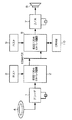
図1は、本発明の実施形態によるデータ送受信システムの構成を示すブロック図である。送信側装置は、デコーダ1と、IEEE1394インターフェース回路2と、ホスト(マイクロコンピュータ)3とからなる。デコーダ1は、スーパー・オーディオCD(SACD)などのメディア4からデータを読み込んで復号化する。IEEE1394インターフェース回路2は、復号化されたデータをIEEE1394規格のアイソクロノスパケットとして、IEEE1394シリアルバスを介して受信側装置へ転送する。ホスト3は、IEEE1394インターフェース回路2に対して送信指示を与える。
【0014】
受信側装置は、IEEE1394インターフェース回路6と、D/A変換回路7と、スピーカ8と、ホスト(マイクロコンピュータ)9と、DRAM10とからなる。IEEE1394インターフェース回路6は、IEEE1394シリアルバスを介して送信側装置から転送されてくるアイソクロノスパケットを受信し、D/A変換回路7へ供給する。D/A変換回路7は、上記データをアナログ信号に変換する。スピーカ8は、D/A変換回路7からのアナログ信号を音声として出力する。ホスト9は、IEEE1394インターフェース回路6の動作を制御する。
【0015】
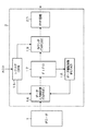
次に、図2は、データ送受信システムにおける送信側装置のIEEE1394インターフェース回路の構成を示すブロック図である。IEEE1394インターフェース回路2は、レジスタ(CFR:Configuration Register)15、データ入力制御部(TXPRE:Tx pre process)16、FIFO17、データ量監視部(FSTAT:Fifo STATus check)18、カウンタ(TXPOST:Tx post process)19、PHY回路(PHY:物理層)20から構成されている。レジスタ15は、ホストからの送信指示(±1%)を格納する。データ入力制御部16は、デコーダ1からのデータを、レジスタ15に格納された送信指示およびデータ量監視部18の制御に従って、デコーダ1に対して当該回路へのデータ転送量を指示するとともに、デコーダ1からのデータをFIFO17に供給する。このとき、IEEE1394送信用のクワドレットに変換する。
【0016】
FIFO17は、バンク単位でデータ入力制御部16からのデータを格納するとともに、順次、カウンタ19へ送出する。データ量監視部18は、FIFO17のデータ容量を監視し(オーバフロー/空)、FIFO17がオーバフローになったり、空になったりしないように、データ入力制御部16に対してデコーダ1へのデータ要求・停止を行う。カウンタ19は、レジスタ15に格納された送信指示に従って、FIFO17から出力されるアイソクロノスパケット送信回数をカウントする(フリーランカウンタ)。また、カウンタ19は、データ転送量を増加するときには、前記所定の転送期間に送信されるパケット群に含まれる空(Empty)パケットの転送時にデータパケットを送信し、データ転送量を減少させるときには、データパケットの送信タイミングで空パケットを送信するようになっている。空パケットは、送信データがないときに転送する、1394ヘッダ、CIP1/2のみからなるパケットである。また、カウンタ19は、送信時に、送信用のIEEE1394クワドレットにヘッダ、CRCを付加する。PHY回路20は、上記FIFO17からのアイソクロノスパケットを実際のIEEE1394バス上に流れる電気信号に変換するとともに、バスを獲得するための調停などを行う。
【0017】
次に、図3は、デコーダとIEEE1394インターフェース回路との接続関係を示すブロック図である。デコーダ1とIEEE1394インターフェース回路2とは、図3に示すように接続され、IEEE1394インターフェース回路2からデコーダ1に対してデータ要求・停止指示を送信することにより、デコーダ1におけるデータ転送期間を制御し、デコーダ1からIEEE1394インターフェース回路2側へ入力されるデータ量を制御するようになっている。dtx2は、デコーダ側への倍速要求信号であり、xreq_outはデコーダ側へのデータ停止要求信号である。
【0018】
IEEE1394インターフェース回路2は、+1%送信時には、FIFO17内のデータが不足する場合が想定されるので、dtx2を「H」とし、デコーダ1に2倍速転送を要求する。そして、データ量監視部18によってFIFO17のFULL(オーバフローの手前)信号が認識されると、デコーダ1側へのデータ要求を停止する。すなわち、dtx2=L/XREQ=Hとする。一方、FULL信号が非アクティブになると、IEEE1394インターフェース回路2は、再び、dtx2を「H」とし、デコーダ1に2倍速転送を要求するようになっている。これは、FIFO17内のデータが空になって、+1%で転送することができなくなることを防止するためである。
【0019】
これに対して、−1%送信時には、IEEE1394バス上への転送速度が遅くなるので、通常書き込みが基本となるが、FIFO17内のデータ量はFULL方向へ増加する。この場合、IEEE1394インターフェース回路2は、FIFO17のデータ容量がオーバフローの手前に達したことを示すFULL信号に従って、XREQ=Hとし、デコーダ1からの転送を停止させるようになっている。
【0020】
B.実施形態の動作
次に、上述した実施形態の動作について説明する。ここで、図4は、図3に示すデコーダとIEEE1394インターフェース回路との制御信号およびデータ授受を示すタイミングチャートである。また、図5は、送信側装置における送信制御を示す概念図である。【0021】
±1%送信の指示は、ホスト3からレジスタ15に書き込まれる。データ入力制御部16は、デコーダ1からのデータをFIFO17に供給する。FIFO17では、バンク単位でデータを格納するとともに、所定の送信タイミングでデータを出力する。カウンタ19では、上記レジスタ15に格納された送信指示に基づいてFIFO17からのアイソクロノスパケットの送信回数をカウントする(フリーランカウンタ)。
【0022】
このとき、FIFO17のデータ容量がオーバフローしないか、空にならないかを、データ量監視部18で監視しながら、オーバフローの直前になるか、空になる直前で、データ入力制御部16を介してデコーダ1へのデータ要求・停止を行う。
【0023】
すなわち、図4に示すタイムチャートのように、+1%送信時には、dtx2=Hとし、デコーダ1に2倍速転送を要求する(2倍速期間)。そして、データ量監視部18によってFIFO17のFULL(オーバフローの手前)信号が認識されると、dtx2=L/xreq_out=Hとし、デコーダ1側へのデータ要求を停止する(停止期間)。一方、FULL信号が非アクティブになると、再び、デコーダ1に2倍速転送を要求する(図示略)。
【0024】
一方、−1%送信時には、バス上への転送速度が遅くなるので、通常書き込みとするが、FIFO17内のデータ量が増加してオーバフローの直前になると、xreq_out=Hとし、デコーダ1からのデータ転送を停止させる。
【0025】
さらに、送信側装置では、図5に示すように、IEEE1394インターフェース回路2において、カウンタ19によるカウント値に従って、IEEE1394バス上にデータを送信するタイミングを制御する。例えば、アイソクロノスサイクルが100回あった場合、通常、データを99回送信し、1回は空パケットを送信する。これを基準に±1%の送受信を制御する。すなわち、+1%送信時には、カウンタ19によりカウントした送信回数に従って、通常ならば空パケットを転送するタイミングでデータパケットを送信する。一方、−1%送信時には、+1%送信時とは逆に、カウンタ19によりカウントした送信回数に従って、送信するタイミングにおいて空パケットを送信する。すなわち、FIFO17にデータが残っていても空パケットを送信する。
【0026】
例えば、スーパー・オーディオCD(SACD)においては100回のアイソクロノスサイクルに91.87回の転送がある。したがって、+1%送信時には92.7887回、−1%送信時には90.9513回、アイソクロノスパケットを転送すればよい。そこで、本実施形態によるIEEE1394インターフェース回路2では、ホスト3から+1%送信の指示が出た際には、100回のアイソクロノスサイクルに93回のアイソクロノスパケットを送信する(厳密には+1.012%になる)。また、−1%送信の指示が出た際には、90回のアイソクロノスパケットを送信する(厳密には−2%になる)。言い換えると、−1%送信時には、90回を越える部分で空パケットを送信する。
【0027】
上述した実施形態によれば、IEEE1394シリアルバスを介してのデータ転送において、送信側装置と受信側装置とで、クロックの非同期化が可能になる。このため、受信側装置は、マスタクロックからデータを読み出せるので、音楽データにノイズが重畳せず、IEEE1394による量子化誤差を無視することができる。
【0028】
【発明の効果】
請求項1記載の発明によれば、保持手段にデータ転送増減値を保持し、バッファ手段に前段回路からのデータを一旦保持し、該保持したデータを所定の送信タイミングで出力する際に、カウント手段により、所定の転送期間における、前記バッファ手段から前記シリアルバス上へ送信されるパケット数をカウントし、送信制御手段により、前記保持手段に保持されているデータ転送増減値および前記カウント手段によるカウント値に基づいて、前記バッファ手段から前記シリアルバス上へ送信されるデータパケット数を増減し、データ転送量を増加するときには、前記所定の転送期間に送信されるパケット群に含まれる空パケットの転送時にデータパケットを送信し、データ転送量を減少させるときには、データパケットの送信タイミングで空パケットを送信するようにしたので、シリアルバスを介してのデータ転送において、容易にフロー制御を実現することができ、また、データにノイズが重畳せず、量子化誤差を無視することができるという利点が得られる。
【0029】
また、請求項2記載の発明によれば、監視手段により、前記バッファ手段に保持されるデータ量を監視し、データ供給量指示手段により、前記監視手段により監視された前記バッファ手段のデータ量と前記保持手段に保持されているデータ転送増減値とに基づいて、前記前段回路に対し、当該装置へのデータ供給量を指示するようにしたので、シリアルバスを介してのデータ転送において、容易に、かつ円滑にフロー制御を実現することができ、また、データにノイズが重畳せず、量子化誤差を無視することができるという利点が得られる。
【0030】
また、請求項3記載の発明によれば、前記シリアルバスを、IEEE1394シリアルバスとしたので、IEEE1394シリアルバスを介してのデータ転送において、容易にフロー制御を実現することができ、また、データにノイズが重畳せず、量子化誤差を無視することができるという利点が得られる。
【0031】
また、請求項4記載の発明によれば、前記前段回路からのデータを一旦保持し、該保持したデータを所定の送信タイミングでシリアルバス上へ送信する際に、所定の転送期間における、シリアルバス上へ送信されるパケット数をカウントし、データ転送増減値および前記カウント値に基づいて、前記シリアルバス上へ送信されるデータパケット数を増減し、データ転送量を増加するときには、前記所定の転送期間に送信されるパケット群に含まれる空パケットの転送時にデータパケットを送信し、データ転送量を減少させるときには、データパケットの送信タイミングで空パケットを送信するようにしたので、シリアルバスを介してのデータ転送において、容易にフロー制御を実現することができ、また、データにノイズが重畳せず、量子化誤差を無視することができるという利点が得られる。
【0032】
また、請求項5記載の発明によれば、前記保持されるデータ量を監視し、前記監視されたデータ量と前記データ転送増減値とに基づいて、前記前段回路に対し、当該装置へのデータ供給量を指示するようにしたので、シリアルバスを介してのデータ転送において、容易に、かつ円滑にフロー制御を実現することができ、また、データにノイズが重畳せず、量子化誤差を無視することができるという利点が得られる。
【0033】
また、請求項6記載の発明によれば、前段回路からのデータを一旦保持し、該保持したデータを所定の送信タイミングで、パケット単位でシリアルバス上へ送信するステップと、所定の転送期間における、シリアルバス上へ送信されるパケット数をカウントするステップと、データ転送増減値および前記カウント値に基づいて、前記シリアルバス上へ送信されるデータパケット数を増減し、データ転送量を増加するときには、前記所定の転送期間に送信されるパケット群に含まれる空パケットの転送時にデータパケットを送信し、データ転送量を減少させるときには、データパケットの送信タイミングで空パケットを送信するステップとをコンピュータに実行させるようにしたので、シリアルバスを介してのデータ転送において、容易にフロー制御を実現することができ、また、データにノイズが重畳せず、量子化誤差を無視することができるという利点が得られる。
【0034】
また、請求項7記載の発明によれば、前記保持されるデータ量を監視するステップと、前記監視されたデータ量と前記データ転送増減値とに基づいて、前記前段回路に対し、当該装置へのデータ供給量を指示するステップとをコンピュータに実行させるようにしたので、シリアルバスを介してのデータ転送において、容易に、かつ円滑にフロー制御を実現することができ、また、データにノイズが重畳せず、量子化誤差を無視することができるという利点が得られる。
【図面の簡単な説明】
【図1】本発明の実施形態によるデータ送受信システムの構成を示すブロック図である。
【図2】データ送受信システムにおける送信側装置のIEEE1394インターフェース回路の構成を示すブロック図である。
【図3】デコーダとIEEE1394インターフェース回路との接続関係を示すブロック図である。
【図4】図3に示すデコーダとIEEE1394インターフェース回路との制御信号およびデータ授受を示すタイミングチャートである。
【図5】送信側装置における送信制御を示す概念図である。
【符号の説明】
1……デコーダ、2……IEEE1394インターフェース回路、3……ホスト、6……IEEE1394インターフェース回路、7……D/A変換回路、8……スピーカ、9……ホスト、15……レジスタ(保持手段)、16……データ入力制御部(データ供給量指示手段)、17……FIFO(バッファ手段)、18……データ量監視部(監視手段)、19……カウンタ(カウント手段、送信制御手段)、20……PHY回路。[0001]
BACKGROUND OF THE INVENTION
The present invention relates to a data transfer apparatus, a data transfer method, and a data transfer program that realize flow control when performing data transfer using an IEEE 1394 serial bus.
[0002]
[Prior art]
Conventionally, IEEE (Institute of Electrical and Electronics Engineers) 1394 serial bus is known as one of the serial bus standards as an interface suitable for portable and desktop computer environments and consumer devices such as audio devices and video devices. ing. Communication according to the IEEE 1394 standard has attracted a great deal of attention because it allows isochronous and asynchronous transfer of data, high-speed transfer (100 to 3200 Mbps), connection of a plurality of devices (nodes), and the like.
[0003]
[Problems to be solved by the invention]
By the way, conventionally, in the IEEE 1394 serial bus, when the flow control is realized, the transmission data amount is controlled by using the application clock of the transmission side device at a variable pitch. However, there is a problem in that flow control cannot be performed with a device that does not support the vari pitch. Further, in the conventional data transfer using the IEEE 1394 serial bus, the clock information is also transferred, so that noise is superimposed or a quantization error occurs during communication. For this reason, in particular, when music data is transferred, there is a problem that sound quality deterioration occurs due to the transfer.
[0004]
Therefore, the present invention provides a data transfer apparatus and data that can easily realize flow control in data transfer via a serial bus, and that noise is not superimposed on data and quantization errors can be ignored. It is an object to provide a transfer method and a data transfer program.
[0005]
[Means for Solving the Problems]
To achieve the above object, a data transfer processing device according to the first aspect of the present invention is a data transfer device for transmitting data supplied from a preceding circuit on a serial bus in units of packets, and holds a data transfer increase / decrease value. Holding means; buffer means for temporarily holding data from the preceding circuit; and outputting the held data at a predetermined transmission timing; and a packet transmitted from the buffer means to the serial bus during a predetermined transfer period Based on the count means for counting the number, the data transfer increase / decrease value held in the holding means and the count value by the count means, the number of data packets transmitted from the buffer means onto the serial bus is increased / decreased , When increasing the data transfer amount, empty packets included in the packet group transmitted during the predetermined transfer period are used. Transmitting data packets during packet transfer, when reducing the amount of data transfer, characterized by comprising a transmission control means for transmitting an empty packet at the transmission timing of data packets.
[ 0006 ]
Further, as a preferred aspect, for example, as in
[ 0007 ]
As a preferred mode, for example, as in
[ 0008 ]
In order to achieve the above object, a data transfer method according to a fourth aspect of the present invention is a data transfer method for transmitting data supplied from a preceding circuit onto a serial bus in units of packets, the data being transferred from the preceding circuit. Is temporarily stored, and when the stored data is transmitted to the serial bus at a predetermined transmission timing, the number of packets transmitted on the serial bus in a predetermined transfer period is counted, and the data transfer increase / decrease value and the count are counted. Based on the value, when increasing or decreasing the number of data packets transmitted on the serial bus and increasing the data transfer amount, the data packets are transferred during the transfer of empty packets included in the packet group transmitted during the predetermined transfer period. transmitted, when reducing the amount of data transfer, especially to send an empty packet at the transmission timing of data packets To.
[ 0009 ]
Further, as a preferred aspect, for example, as in claim 5, in the data transfer method according to
[ 0010 ]
In order to achieve the above object, a data transfer program according to a sixth aspect of the present invention temporarily holds data from the preceding circuit and transmits the held data to the serial bus in packet units at a predetermined transmission timing. a method, in a given transfer period, the steps of counting the number of packets to be transmitted onto the serial bus, the data transfer variable and based on the count value, and increasing or decreasing the number of data packets transmitted on the serial bus When increasing the data transfer amount, a data packet is transmitted at the time of transferring an empty packet included in the packet group transmitted during the predetermined transfer period, and when decreasing the data transfer amount, an empty packet is transmitted at the transmission timing of the data packet. The step of transmitting is executed by a computer.
[ 0011 ]
As a preferred aspect, for example, as in claim 7, in the data transfer program according to claim 6 , the step of monitoring the amount of data held, the monitored data amount, and the data transfer increase / decrease value, Based on the above, the computer may be caused to execute a step of instructing the data supply amount to the device for the preceding circuit.
[ 0012 ]
In the present invention, the data transfer increase / decrease value is held in the holding means. When the buffer means temporarily holds the data from the previous circuit and outputs the held data at a predetermined transmission timing, the count means transmits the data from the buffer means to the serial bus during a predetermined transfer period. The number of packets is counted, and the number of data packets transmitted from the buffer means to the serial bus is determined by the transmission control means based on the data transfer increase / decrease value held in the holding means and the count value by the counting means. Increase or decrease. Therefore, it is possible to easily realize flow control in data transfer via the serial bus, and it is possible to ignore the quantization error without superimposing noise on the data.
[ 0013 ]
DETAILED DESCRIPTION OF THE INVENTION
Hereinafter, embodiments of the present invention will be described with reference to the drawings.
A. Configuration of Embodiment FIG. 1 is a block diagram showing a configuration of a data transmission / reception system according to an embodiment of the present invention. The transmission side device includes a
[ 0014 ]
The receiving side device includes an IEEE 1394 interface circuit 6, a D / A conversion circuit 7, a speaker 8, a host (microcomputer) 9, and a
[ 0015 ]
Next, FIG. 2 is a block diagram showing the configuration of the IEEE 1394 interface circuit of the transmission side apparatus in the data transmission / reception system. The IEEE 1394
[ 0016 ]
The
[ 0017 ]
FIG. 3 is a block diagram showing a connection relationship between the decoder and the
[ 0018 ]
The
[ 0019 ]
On the other hand, at the time of -1% transmission, the transfer rate on the
[ 0020 ]
B. Operation of Embodiment Next, the operation of the above-described embodiment will be described. FIG. 4 is a timing chart showing control signals and data exchange between the decoder shown in FIG. 3 and the
The ± 1% transmission instruction is written from the
[ 0022 ]
At this time, the data amount monitoring
[ 0023 ]
That is, as shown in the time chart of FIG. 4, at the time of + 1% transmission, dtx2 = H is set, and the
[ 0024 ]
On the other hand, at the time of -1% transmission, the transfer speed on the bus becomes slow, so normal writing is performed. However, when the amount of data in the
[ 0025 ]
Further, as shown in FIG. 5, the transmission side apparatus controls the timing of transmitting data on the
[ 0026 ]
For example, in Super Audio CD (SACD), there are 91.87 transfers in 100 isochronous cycles. Therefore, an isochronous packet may be transferred 92.7878 times for + 1% transmission and 90.9513 times for -1% transmission. Therefore, in the
[ 0027 ]
According to the above-described embodiment, in the data transfer via the
[ 0028 ]
【The invention's effect】
According to the first aspect of the present invention, the data transfer increase / decrease value is held in the holding means, the data from the previous circuit is temporarily held in the buffer means, and the stored data is output at a predetermined transmission timing. Means for counting the number of packets transmitted from the buffer means onto the serial bus during a predetermined transfer period, and the transmission control means counts the data transfer increase / decrease value held in the holding means and the count means counts. When the number of data packets transmitted from the buffer means to the serial bus is increased or decreased based on the value to increase the data transfer amount, transfer of empty packets included in the packet group transmitted during the predetermined transfer period Sometimes when sending data packets and reducing the amount of data transfer, Since so as to transmit the packet, the data transfer via the serial bus, it is possible to easily realize a flow control, also, noise is not superimposed on the data, being able to ignore quantization error Benefits are gained.
[ 0029 ]
According to the second aspect of the present invention, the monitoring unit monitors the amount of data held in the buffer unit, and the data supply amount instruction unit monitors the data amount of the buffer unit monitored by the monitoring unit. Based on the data transfer increase / decrease value held in the holding means, the previous circuit is instructed about the amount of data supplied to the device, so that data transfer via the serial bus is easy. In addition, the flow control can be realized smoothly, and there is an advantage that noise is not superimposed on the data and the quantization error can be ignored.
[ 0030 ]
According to the third aspect of the present invention, since the serial bus is an
[ 0031 ]
According to a fourth aspect of the present invention, when the data from the preceding circuit is temporarily held and the held data is transmitted onto the serial bus at a predetermined transmission timing, the serial bus in a predetermined transfer period When the number of packets transmitted upward is counted and the number of data packets transmitted on the serial bus is increased or decreased based on the data transfer increase / decrease value and the count value, the predetermined transfer is performed. Data packets are transmitted during transfer of empty packets included in a group of packets transmitted during the period, and when reducing the amount of data transfer, empty packets are transmitted at the transmission timing of data packets. Can easily realize flow control, and no noise is superimposed on the data. The advantage is obtained that it is possible to ignore the difference.
[ 0032 ]
According to a fifth aspect of the present invention, the data amount to be held is monitored, and the data to the device is sent to the preceding circuit based on the monitored data amount and the data transfer increase / decrease value. Since the supply amount is instructed, flow control can be realized easily and smoothly in data transfer via the serial bus, noise is not superimposed on the data, and quantization errors are ignored. The advantage of being able to do is obtained.
[ 0033 ]
According to the sixth aspect of the present invention, the step of temporarily holding the data from the previous circuit and transmitting the held data to the serial bus in units of packets at a predetermined transmission timing; The step of counting the number of packets transmitted on the serial bus, the data transfer increase / decrease value, and the count value are used to increase / decrease the number of data packets transmitted on the serial bus to increase the data transfer amount. Transmitting a data packet at the time of transferring an empty packet included in a packet group transmitted during the predetermined transfer period and reducing the amount of data transfer to the computer by transmitting the empty packet at the transmission timing of the data packet. Since it is executed, it is easy to flow in data transfer via the serial bus. Control can be realized, also data without noise superimposed to obtain the advantage of being able to ignore the quantization error.
[ 0034 ]
According to the seventh aspect of the present invention, based on the monitored data amount, the monitored data amount and the data transfer increase / decrease value, the preceding circuit is transferred to the device. The step of instructing the data supply amount is executed by the computer, so that flow control can be realized easily and smoothly in data transfer via the serial bus, and there is noise in the data. There is an advantage that the quantization error can be ignored without superimposing.
[Brief description of the drawings]
FIG. 1 is a block diagram showing a configuration of a data transmission / reception system according to an embodiment of the present invention.
FIG. 2 is a block diagram showing a configuration of an
FIG. 3 is a block diagram showing a connection relationship between a decoder and an
4 is a timing chart showing control signals and data exchange between the decoder shown in FIG. 3 and an
FIG. 5 is a conceptual diagram illustrating transmission control in a transmission-side apparatus.
[Explanation of symbols]
DESCRIPTION OF
Claims (7)
データ転送増減値を保持する保持手段と、
前記前段回路からのデータを一旦保持し、該保持したデータを所定の送信タイミングで出力するバッファ手段と、
所定の転送期間における、前記バッファ手段から前記シリアルバス上へ送信されるパケット数をカウントするカウント手段と、
前記保持手段に保持されているデータ転送増減値および前記カウント手段によるカウント値に基づいて、前記バッファ手段から前記シリアルバス上へ送信されるデータパケット数を増減し、データ転送量を増加するときには、前記所定の転送期間に送信されるパケット群に含まれる空パケットの転送時にデータパケットを送信し、データ転送量を減少させるときには、データパケットの送信タイミングで空パケットを送信する送信制御手段と
を具備することを特徴とするデータ転送処理装置。A data transfer device that transmits data supplied from a preceding circuit onto a serial bus in units of packets,
Holding means for holding data transfer increase / decrease values;
Buffer means for temporarily holding data from the preceding circuit and outputting the held data at a predetermined transmission timing;
Counting means for counting the number of packets transmitted from the buffer means onto the serial bus in a predetermined transfer period;
Based on the data transfer increase / decrease value held in the holding means and the count value by the count means , when increasing / decreasing the number of data packets transmitted from the buffer means onto the serial bus , Transmission control means for transmitting a data packet at the time of transferring an empty packet included in the packet group transmitted during the predetermined transfer period and transmitting the empty packet at the data packet transmission timing when reducing the data transfer amount. A data transfer processing device.
前記監視手段により監視された前記バッファ手段のデータ量と前記保持手段に保持されているデータ転送増減値とに基づいて、前記前段回路に対し、当該装置へのデータ供給量を指示するデータ供給量指示手段と
を具備することを特徴とする請求項1記載のデータ転送処理装置。Monitoring means for monitoring the amount of data held in the buffer means;
Based on the data amount of the buffer means monitored by the monitoring means and the data transfer increase / decrease value held in the holding means, the data supply amount for instructing the data supply amount to the apparatus to the preceding circuit The data transfer processing device according to claim 1, further comprising an instruction unit.
前記前段回路からのデータを一旦保持し、該保持したデータを所定の送信タイミングでシリアルバス上へ送信する際に、
所定の転送期間における、シリアルバス上へ送信されるパケット数をカウントし、
データ転送増減値および前記カウント値に基づいて、前記シリアルバス上へ送信されるデータパケット数を増減し、データ転送量を増加するときには、前記所定の転送期間に送信されるパケット群に含まれる空パケットの転送時にデータパケットを送信し、
データ転送量を減少させるときには、データパケットの送信タイミングで空パケットを送信する
ことを特徴とするデータ転送方法。A data transfer method for transmitting data supplied from a preceding circuit onto a serial bus in units of packets,
When temporarily holding the data from the previous circuit and transmitting the held data to the serial bus at a predetermined transmission timing,
Count the number of packets sent on the serial bus during a given transfer period,
Based on the data transfer increase / decrease value and the count value, the number of data packets transmitted on the serial bus is increased / decreased to increase the data transfer amount, and the empty packet included in the packet group transmitted during the predetermined transfer period is increased. Send data packets when transferring packets,
An empty packet is transmitted at a data packet transmission timing when the data transfer amount is reduced .
前記監視されたデータ量と前記データ転送増減値とに基づいて、前記前段回路に対し、当該装置へのデータ供給量を指示することを特徴とする請求項4記載のデータ転送方法。Monitoring the amount of data retained;
5. The data transfer method according to claim 4 , wherein a data supply amount to the device is instructed to the pre-stage circuit based on the monitored data amount and the data transfer increase / decrease value.
所定の転送期間における、シリアルバス上へ送信されるパケット数をカウントするステップと、
データ転送増減値および前記カウント値に基づいて、前記シリアルバス上へ送信されるデータパケット数を増減し、データ転送量を増加するときには、前記所定の転送期間に送信されるパケット群に含まれる空パケットの転送時にデータパケットを送信し、データ転送量を減少させるときには、データパケットの送信タイミングで空パケットを送信するステップと をコンピュータに実行させることを特徴とするデータ転送プログラム。Temporarily holding data from the previous circuit, and transmitting the held data to the serial bus in units of packets at a predetermined transmission timing;
Counting the number of packets transmitted on the serial bus during a predetermined transfer period;
Based on the data transfer increase / decrease value and the count value, the number of data packets transmitted on the serial bus is increased / decreased to increase the data transfer amount, and the empty packet included in the packet group transmitted during the predetermined transfer period is increased. A data transfer program for causing a computer to execute a step of transmitting a data packet at the time of packet transfer and transmitting an empty packet at the transmission timing of the data packet when reducing the amount of data transfer.
前記監視されたデータ量と前記データ転送増減値とに基づいて、前記前段回路に対し、当該装置へのデータ供給量を指示するステップと
をコンピュータに実行させることを特徴とする請求項6記載のデータ転送プログラム。Monitoring the amount of data retained;
7. The computer according to claim 6, further comprising: causing the computer to execute a step of instructing a data supply amount to the device based on the monitored data amount and the data transfer increase / decrease value. Data transfer program.
Priority Applications (2)
| Application Number | Priority Date | Filing Date | Title |
|---|---|---|---|
| JP2001157173A JP3633507B2 (en) | 2001-05-25 | 2001-05-25 | Data transfer processing device, data transfer method, and data transfer program |
| US10/155,495 US7177280B2 (en) | 2001-05-25 | 2002-05-23 | Data transfer processing apparatus, data transfer method, and data transfer program |
Applications Claiming Priority (1)
| Application Number | Priority Date | Filing Date | Title |
|---|---|---|---|
| JP2001157173A JP3633507B2 (en) | 2001-05-25 | 2001-05-25 | Data transfer processing device, data transfer method, and data transfer program |
Publications (2)
| Publication Number | Publication Date |
|---|---|
| JP2002354051A JP2002354051A (en) | 2002-12-06 |
| JP3633507B2 true JP3633507B2 (en) | 2005-03-30 |
Family
ID=19001071
Family Applications (1)
| Application Number | Title | Priority Date | Filing Date |
|---|---|---|---|
| JP2001157173A Expired - Fee Related JP3633507B2 (en) | 2001-05-25 | 2001-05-25 | Data transfer processing device, data transfer method, and data transfer program |
Country Status (2)
| Country | Link |
|---|---|
| US (1) | US7177280B2 (en) |
| JP (1) | JP3633507B2 (en) |
Families Citing this family (8)
| Publication number | Priority date | Publication date | Assignee | Title |
|---|---|---|---|---|
| US6782208B1 (en) * | 1999-11-16 | 2004-08-24 | Motorola, Inc. | Wireless communication device and method having coordinated primary and secondary transmitters |
| JP4217386B2 (en) * | 2001-05-15 | 2009-01-28 | 株式会社リコー | FIFO device |
| US7599456B1 (en) * | 2004-12-13 | 2009-10-06 | Marvell International Ltd. | Input/output data rate synchronization using first in first out data buffers |
| US8126030B2 (en) * | 2005-08-31 | 2012-02-28 | Motorola Mobility, Inc. | Multi-mode wireless communication device and method |
| US7894435B2 (en) * | 2006-09-14 | 2011-02-22 | Intel Corporation | Indicator packets for process/forward decision |
| US20100035562A1 (en) * | 2008-08-05 | 2010-02-11 | Motorola, Inc. | Method and System for Signal Processing and Transmission |
| CN102460972B (en) * | 2009-06-30 | 2015-10-14 | 拉姆伯斯公司 | For adjusting clock signal with the method for comfort noise, system and integrated circuit |
| US10447461B2 (en) * | 2015-12-01 | 2019-10-15 | Infineon Technologies Austria Ag | Accessing data via different clocks |
Family Cites Families (7)
| Publication number | Priority date | Publication date | Assignee | Title |
|---|---|---|---|---|
| JPH1065758A (en) * | 1996-08-23 | 1998-03-06 | Sony Corp | Data transmitting method and device therefor |
| JPH11275122A (en) * | 1998-03-25 | 1999-10-08 | Sony Corp | Data transmitter |
| JP4112717B2 (en) * | 1998-12-10 | 2008-07-02 | 日本テキサス・インスツルメンツ株式会社 | Data processing device |
| JP2001156807A (en) * | 1999-09-14 | 2001-06-08 | Sony Corp | Method, system, and device for transmission |
| JP2001230821A (en) * | 2000-02-16 | 2001-08-24 | Sony Corp | Data repeater and method, and serving medium |
| JP2001244952A (en) * | 2000-02-29 | 2001-09-07 | Sony Corp | Communication controller |
| US6940873B2 (en) * | 2000-12-27 | 2005-09-06 | Keen Personal Technologies, Inc. | Data stream control system for associating counter values with stored selected data packets from an incoming data transport stream to preserve interpacket time interval information |
-
2001
- 2001-05-25 JP JP2001157173A patent/JP3633507B2/en not_active Expired - Fee Related
-
2002
- 2002-05-23 US US10/155,495 patent/US7177280B2/en not_active Expired - Fee Related
Also Published As
| Publication number | Publication date |
|---|---|
| US20020176425A1 (en) | 2002-11-28 |
| US7177280B2 (en) | 2007-02-13 |
| JP2002354051A (en) | 2002-12-06 |
Similar Documents
| Publication | Publication Date | Title |
|---|---|---|
| US9558142B2 (en) | Split transaction protocol for a bus system | |
| KR100381646B1 (en) | Data transfer control device and electronic equipment | |
| US6792495B1 (en) | Transaction scheduling for a bus system | |
| KR100464468B1 (en) | Data transfer controller and electronic device | |
| JP2009506682A (en) | Explicit flow control in gigabit / 10 gigabit ethernet systems | |
| KR19990088404A (en) | Method and apparatus transmitting data over data bus at maximum speed | |
| JP3584789B2 (en) | Data transfer control device and electronic equipment | |
| KR100405250B1 (en) | Data transfer control device and electronic apparatus | |
| JP3633507B2 (en) | Data transfer processing device, data transfer method, and data transfer program | |
| JP3780776B2 (en) | Data transfer control device and electronic device | |
| US6580711B1 (en) | Serial interface circuit and signal processing method of the same | |
| US9571397B2 (en) | Flow control mechanisms on synchronous serial TDMA bus | |
| JP3539287B2 (en) | Data transfer control device and electronic equipment | |
| JP3494040B2 (en) | Data transfer control device and electronic equipment | |
| KR100464469B1 (en) | Data transfer controller and electronic device | |
| US20040019712A1 (en) | Semiconductor device and method for controlling data transfer | |
| JP5776346B2 (en) | Communication apparatus, network system, and packet processing method | |
| JP2004235747A (en) | Data transmission method, data transmission device and data transmission system | |
| JP2003196227A (en) | Data transfer method in bus interface and bus interface | |
| JP2003167844A (en) | Data transferring method in bus interface, and bus interface | |
| JP2000151738A (en) | Data processor, data transmission system and method therefor | |
| JP2005267324A (en) | Private branch exchange and data transfer processing system | |
| JP2002288107A (en) | Device and method for data transfer, program and recording medium | |
| JP2002077309A (en) | Signal-processing circuit | |
| JP2004118704A (en) | Interface device and its control method |
Legal Events
| Date | Code | Title | Description |
|---|---|---|---|
| A977 | Report on retrieval |
Free format text: JAPANESE INTERMEDIATE CODE: A971007 Effective date: 20040426 |
|
| A131 | Notification of reasons for refusal |
Free format text: JAPANESE INTERMEDIATE CODE: A131 Effective date: 20040511 |
|
| A521 | Written amendment |
Free format text: JAPANESE INTERMEDIATE CODE: A523 Effective date: 20040618 |
|
| RD02 | Notification of acceptance of power of attorney |
Free format text: JAPANESE INTERMEDIATE CODE: A7422 Effective date: 20040621 |
|
| TRDD | Decision of grant or rejection written | ||
| A01 | Written decision to grant a patent or to grant a registration (utility model) |
Free format text: JAPANESE INTERMEDIATE CODE: A01 Effective date: 20041207 |
|
| A61 | First payment of annual fees (during grant procedure) |
Free format text: JAPANESE INTERMEDIATE CODE: A61 Effective date: 20041220 |
|
| FPAY | Renewal fee payment (event date is renewal date of database) |
Free format text: PAYMENT UNTIL: 20080107 Year of fee payment: 3 |
|
| FPAY | Renewal fee payment (event date is renewal date of database) |
Free format text: PAYMENT UNTIL: 20090107 Year of fee payment: 4 |
|
| FPAY | Renewal fee payment (event date is renewal date of database) |
Free format text: PAYMENT UNTIL: 20100107 Year of fee payment: 5 |
|
| FPAY | Renewal fee payment (event date is renewal date of database) |
Free format text: PAYMENT UNTIL: 20100107 Year of fee payment: 5 |
|
| FPAY | Renewal fee payment (event date is renewal date of database) |
Free format text: PAYMENT UNTIL: 20110107 Year of fee payment: 6 |
|
| FPAY | Renewal fee payment (event date is renewal date of database) |
Free format text: PAYMENT UNTIL: 20110107 Year of fee payment: 6 |
|
| FPAY | Renewal fee payment (event date is renewal date of database) |
Free format text: PAYMENT UNTIL: 20120107 Year of fee payment: 7 |
|
| FPAY | Renewal fee payment (event date is renewal date of database) |
Free format text: PAYMENT UNTIL: 20130107 Year of fee payment: 8 |
|
| R250 | Receipt of annual fees |
Free format text: JAPANESE INTERMEDIATE CODE: R250 |
|
| R250 | Receipt of annual fees |
Free format text: JAPANESE INTERMEDIATE CODE: R250 |
|
| LAPS | Cancellation because of no payment of annual fees |