JP3633382B2 - Functional block connection device and functional block connection method - Google Patents
Functional block connection device and functional block connection method Download PDFInfo
- Publication number
- JP3633382B2 JP3633382B2 JP20543499A JP20543499A JP3633382B2 JP 3633382 B2 JP3633382 B2 JP 3633382B2 JP 20543499 A JP20543499 A JP 20543499A JP 20543499 A JP20543499 A JP 20543499A JP 3633382 B2 JP3633382 B2 JP 3633382B2
- Authority
- JP
- Japan
- Prior art keywords
- functional block
- bus
- access
- functional
- detection signal
- Prior art date
- Legal status (The legal status is an assumption and is not a legal conclusion. Google has not performed a legal analysis and makes no representation as to the accuracy of the status listed.)
- Expired - Fee Related
Links
Images


Landscapes
- Mounting Of Printed Circuit Boards And The Like (AREA)
Description
【0001】
【発明の属する技術分野】
本発明は、電気回路および電気素子を有する複数の機能ブロックをバスに接続する機能ブロック接続装置および機能ブロック接続方法に関する。
【0002】
【従来の技術】
従来より、交換機システムにおいて、各機能ブロックを制御するためにバス構成を用いて接続を行うように構成された様々なシステムが採用されている。このようなシステムにおいて、バスに対して機能ブロックを追加しようとした場合、既に運用している動作に対して障害とならないよう様々な対策が採られている。図5に示すような、従来の機能ブロック接続方法の1つとして、機能ブロックを挿入して物理的にバスに接続する物理的接続ステップS11と、機能ブロックの動作を確認する動作確認ステップS12と、前記機能ブロックを前記バスに論理的に接続する論理的接続ステップ13とを有するものがある。
【0003】
【発明が解決しようとする課題】
しかし、従来の機能ブロック接続方法においては、動作(アクセス)中のバスの状態に関わらず、追加される機能ブロックの機能が正常である確認が終了すると当該機能ブロックが論理的にバスに接続されてしまうため、バスに接続したと同時に前記確認時において他の機能ブロックの間同士でアクセスをおこなっている場合であっても、このアクセスに追加された機能ブロックも他の機能ブロックの間同士のアクセスに反応してしまうといった可能性があるという問題がある。
【0004】
例えば、図6に示すように、機能ブロックA11、A12、A13は、交換機における各機能を実現する機能ブロックであり、物理的にも論理的にも既にバスB11に接続されている状態である。機能ブロックA14を、今まさにバスに接続しようとしている新規の機能ブロックを表わしているものとする。そして機能ブロックA12、A13、A14は機能ブロックA11によって制御されるものとし、機能ブロックA14の接続時には機能ブロックA11から機能ブロックA13へアクセス中であるものとする。このような状態のときに、図7に示すように、新たに機能ブロックA14をバスB11に接続した場合、本来なら機能ブロックA11は、機能ブロックA13とは独占的にアクセスしているにも関わらず、新たに機能ブロックA14が新たに付加されたことによって、機能ブロックA14が自分へのアクセスと誤認識して誤動作しまう虞が生じる可能性があるという問題がある。
【0005】
本発明の目的は、機能ブロックをバスに接続する時に接続する機能ブロックの誤動作を防止することができる機能ブロック接続装置および機能ブロック接続方法を提供することにある。
【0006】
【課題を解決するための手段】
前記課題を解決するために、請求項1に記載の発明は、電気回路および電気素子を有する複数の機能ブロックをバスに接続する機能ブロック接続装置において、前記各機能ブロックは、前記バスに既に接続されている前記機能ブロックがアクセスをしていることを検出してアクセス時間検出信号を発生するアクセス検出手段と、このアクセス検出手段が前記アクセス時間検出信号を発生していない時に当該各前記各機能ブロックを前記バスに論理的に接続する論理的接続手段とを有することを特徴とする。
【0007】
請求項2に記載の発明は、電気回路および電気素子を有する複数の機能ブロックをバスに接続する機能ブロック接続装置において、前記各機能ブロックは、当該各機能ブロックを物理的に前記バスに接続する物理的接続手段と、前記バスに既に接続されている前記機能ブロックがアクセスをしていることを検出してアクセス時間検出信号を発生するアクセス検出手段と、このアクセス検出手段が前記アクセス時間検出信号を発生していない時に当該各機能ブロックを前記バスに論理的に接続する論理的接続手段とを有することを特徴とする。
【0008】
請求項3に記載の発明は、前記請求項1または2において、前記アクセス信号が、バス使用信号であることを特徴とする。
【0009】
請求項4に記載の発明は、電気回路および電気素子を有する複数の機能ブロックをバスに接続する機能ブロック接続方法において、前記各機能ブロックのアクセス検出手段が前記バスに既に接続されている前記機能ブロックがアクセスをしていることを検出してアクセス時間検出信号を発生するアクセス検出ステップと、前記アクセス検出手段が前記アクセス時間検出信号を発生していない時に当該各機能ブロックを前記バスに当該各機能ブロックの論理的接続手段が論理的に接続する論理的接続ステップとを有することを特徴とする。
【0010】
請求項5に記載の発明は、電気回路および電気素子を有する複数の機能ブロックをバスに接続する機能ブロック接続方法において、前記各機能ブロックの物理的接続手段が当該各機能ブロックを物理的に前記バスに接続する物理的接続ステップと、前記バスに既に接続されている前記機能ブロックがアクセスをしていることを当該各機能ブロックのアクセス検出手段が検出してアクセス時間検出信号を発生するアクセス検出ステップと、前記アクセス検出手段が前記アクセス時間検出信号を発生していない時に当該各機能ブロックを前記バスに当該各機能ブロックの論理的接続手段が論理的に接続する論理的接続ステップとを有することを特徴とする。
【0011】
請求項6に記載の発明は、電気回路および電気素子を有する複数の機能ブロックをバスに接続する機能ブロック接続方法において、前記各機能ブロックのアクセス検出手段が前記バスに既に接続されている前記機能ブロックがアクセスをしていることを示すバス使用信号を検出してアクセス時間検出信号を発生するアクセス検出ステップと、前記アクセス検出手段が前記アクセス時間検出信号を発生していない時に当該各機能ブロックを前記バスに当該各機能ブロックの論理的接続手段が論理的に接続する論理的接続ステップとを有することを特徴とする。
【0012】
請求項7に記載の発明は、電気回路および電気素子を有する複数の機能ブロックをバスに接続する機能ブロック接続方法において、前記各機能ブロックの物理的接続手段が当該各機能ブロックを物理的に前記バスに接続する物理的接続手段と、前記バスに既に接続されている前記機能ブロックがアクセスをしていることを示すバス使用信号を当該各機能ブロックのアクセス検出手段が検出してアクセス時間検出信号を発生するアクセス検出ステップと、前記アクセス検出手段が前記アクセス時間検出信号を発生していない時に当該各機能ブロックを前記バスに当該各機能ブロックの論理的接続手段が論理的に接続する論理的接続ステップとを有することを特徴とする。
【0013】
【発明の実施の形態】
次に、発明の実施の形態を図面に基づいて詳細に説明する。
本発明の1つの実施の形態としての機能ブロック接続装置は、図1に示すように、電気回路および電気素子を有する複数の機能ブロックA1、A2、A3、・・・、A4をバスB1に接続する機能ブロック接続装置において、各機能ブロックA1、A2、A3、・・・、A4は、当該各機能ブロックA1、A2、A3、・・・、A4を物理的にバスB1に接続する物理的接続手段1と、バスB1に既に接続されている前記機能ブロックA1、A2、A3の1つがアクセスをしていることを示すバス使用信号を検出してアクセス時間検出信号を発生するアクセス検出手段2と、このアクセス検出手段2が前記アクセス時間検出信号を発生していない時に当該各機能ブロックA1、A2、A3、・・・、A4を前記バスB1に論理的に接続する論理的接続手段3とを有している。
【0014】
例えば、図1に示すように、機能ブロックA1、A2、A3は、交換機における各機能を実現する機能ブロックであり、物理的にも論理的にも既にバスB1に接続されている状態を示す。また機能ブロックA4は、バスに接続しようとしている新規の機能ブロックを表わしているものとする。機能ブロックA2、A3、A4は機能ブロックA1によって制御され、機能ブロックA4の接続時には機能ブロックA1から機能ブロックA3へアクセス中であるものとする。ここで、図2に示すように、本発明の機能ブロック接続装置においては、新たに機能ブロックA4をバスB1に接続する場合に、物理的接続手段1により機能ブロックA4をバスB1に物理的に接続し、バスB1に既に接続されている前記機能ブロックA1、A2、A3の1つがアクセスをしていることを示すバス使用信号をアクセス検出手段2が検出してアクセス時間検出信号を発生し、次にアクセス検出手段2が前記アクセス時間検出信号を発生していない時に当該各機能ブロックA4をバスB1に論理的接続手段3が論理的に接続するものである。
【0015】
図3に示すように、前記バス使用信号Cは、機能ブロックA1、A2、A3の1つがアクセス中である時にローレベルとなり、機能ブロックA1、A2、A3の全部がアクセス中でない時(非アクセス中)にハイレベルとなる。アクセス検出手段2は、バス使用信号Cを検出してバス使用信号Cがローレベルである時にのみアクセス時間検出信号を発生して論理的接続手段3に伝達する。この論理的接続手段3は、アクセス検出手段2からのアクセス時間検出信号を受けていない時にのみ当該各機能ブロックA4をバスB1に論理的に接続する。
【0016】
すなわち、本発明の機能ブロック接続装置においては、各機能ブロックA1、A2、A3、A4ごとにバスアクセス状況を監視する機能を持たせ、アクセス中であるならばそのアクセスが終了するまで論理的にバスB1に接続させないようにする。このようにして機能ブロックA4の物理的な接続によって、即時にバスB1に論理的に接続するのではなく、機能ブロックA4をバスB1に論理的に接続するタイミングを調整することにより、本発明では誤動作を防止している。
【0017】
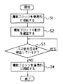
次に、本発明の機能ブロック接続方法を図4に基づいて説明する。電気回路および電気素子を有する複数の機能ブロックをバスに接続する機能ブロック接続方法において、まず、ステップS1において各機能ブロックの物理的接続手段1が当該各機能ブロックを物理的に前記バスに接続する。次に、ステップS2において各機能ブロックの動作を確認する。次に、ステップS3においてバスに既に接続されている機能ブロックがアクセスをしていることを示すバス使用信号を当該各機能ブロックのアクセス検出手段2が検出しているかを判断する。テップS3においてバス使用信号を当該各機能ブロックのアクセス検出手段2が検出していない時、すなわち、アクセス検出手段2がアクセス時間検出信号を発生していない時に、ステップS4において当該各機能ブロックをバスに当該各機能ブロックの論理的接続手段3が論理的に接続する。
【0018】
【発明の効果】
本発明によれば、機能ブロックをバスに接続する時に、接続する機能ブロックの誤動作を防止することができる。
【図面の簡単な説明】
【図1】本発明の1つの実施の形態としての機能ブロック接続装置を示すブロック図である。
【図2】図1の機能ブロック接続装置の構成および動作を説明するためのブロック図である。
【図3】図1の機能ブロック接続装置におけるバス使用信号を説明するための図である。
【図4】本発明の1つの実施の形態としての機能ブロック接続方法を説明するためのフローチャートである。
【図5】従来の機能ブロック接続方法を説明するためのフローチャートである。
【図6】従来の機能ブロック接続方法を説明するためのブロック図である。
【図7】従来の機能ブロック接続方法を説明するための他のブロック図である。
【符号の説明】
A1〜A4 機能ブロック
B1 バス
1 物理的接続手段
2 アクセス検出手段
3 論理的接続手段[0001]
BACKGROUND OF THE INVENTION
The present invention relates to a functional block connection device and a functional block connection method for connecting a plurality of functional blocks each having an electric circuit and an electric element to a bus.
[0002]
[Prior art]
2. Description of the Related Art Conventionally, in a switching system, various systems configured to connect using a bus configuration to control each functional block have been adopted. In such a system, when a functional block is added to the bus, various measures are taken so as not to cause an obstacle to the operation already in operation. As one of the conventional functional block connection methods as shown in FIG. 5, a physical connection step S11 for inserting a functional block and physically connecting it to the bus, and an operation confirmation step S12 for confirming the operation of the functional block, And a logical connection step 13 for logically connecting the functional block to the bus.
[0003]
[Problems to be solved by the invention]
However, in the conventional function block connection method, the function block is logically connected to the bus after the confirmation that the function of the function block to be added is normal regardless of the state of the bus being operated (accessed). Therefore, even if the access is made between other functional blocks at the time of the confirmation at the same time as the connection to the bus, the function block added to this access is also between the other functional blocks. There is a problem that it may react to access.
[0004]
For example, as shown in FIG. 6, functional blocks A11, A12, and A13 are functional blocks that realize each function in the exchange and are already physically and logically connected to the bus B11. Let functional block A14 represent the new functional block that is just about to be connected to the bus. The function blocks A12, A13, and A14 are controlled by the function block A11. When the function block A14 is connected, the function block A11 is accessing the function block A13. In this state, as shown in FIG. 7, when a new function block A14 is connected to the bus B11, the function block A11 is originally accessed exclusively by the function block A13. However, there is a problem that there is a possibility that the function block A14 may be erroneously recognized as access to itself and malfunction due to the newly added function block A14.
[0005]
An object of the present invention is to provide a functional block connection device and a functional block connection method capable of preventing malfunction of a functional block connected when the functional block is connected to a bus.
[0006]
[Means for Solving the Problems]
In order to solve the above-mentioned problem, the invention according to claim 1 is a functional block connection device for connecting a plurality of functional blocks having an electric circuit and an electric element to a bus, wherein each functional block is already connected to the bus. An access detection means for detecting that the function block being accessed is accessing and generating an access time detection signal, and each of the functions when the access detection means does not generate the access time detection signal Logical connection means for logically connecting blocks to the bus.
[0007]
According to a second aspect of the present invention, in the functional block connection device for connecting a plurality of functional blocks having an electric circuit and an electric element to a bus, each of the functional blocks physically connects the functional block to the bus. Physical connection means, access detection means for detecting that the functional block already connected to the bus is accessing and generating an access time detection signal, and the access detection means is the access time detection signal And a logical connection means for logically connecting the functional blocks to the bus when no error occurs.
[0008]
According to a third aspect of the present invention, in the first or second aspect, the access signal is a bus use signal.
[0009]
According to a fourth aspect of the present invention, in the functional block connection method for connecting a plurality of functional blocks each having an electric circuit and an electric element to a bus, the function in which the access detection means of each functional block is already connected to the bus An access detection step for detecting that the block is accessing and generating an access time detection signal; and when the access detection means does not generate the access time detection signal, the function blocks are connected to the bus. The function block logical connection means includes a logical connection step for logical connection.
[0010]
According to a fifth aspect of the present invention, in the functional block connection method for connecting a plurality of functional blocks each having an electric circuit and an electric element to a bus, the physical connection means of the functional blocks physically connects the functional blocks. A physical connection step for connecting to the bus, and an access detection for generating an access time detection signal by detecting that the function block already connected to the bus is accessing the function block access detecting means And a logical connection step in which each functional block is logically connected to the bus when the access detecting means does not generate the access time detection signal. It is characterized by.
[0011]
According to a sixth aspect of the present invention, in the functional block connection method for connecting a plurality of functional blocks having an electric circuit and an electric element to a bus, the function in which the access detection means of each functional block is already connected to the bus An access detection step of detecting a bus use signal indicating that the block is accessing and generating an access time detection signal; and when the access detection means does not generate the access time detection signal, And a logical connection step in which logical connection means of each functional block is logically connected to the bus.
[0012]
According to a seventh aspect of the present invention, in the functional block connection method for connecting a plurality of functional blocks each having an electric circuit and an electric element to a bus, the physical connection means of the functional blocks physically connects the functional blocks. An access time detection signal when a physical connection means connected to the bus and a bus use signal indicating that the functional block already connected to the bus is accessing are detected by the access detection means of each functional block. And a logical connection in which each functional block is logically connected to the bus when the access detecting means does not generate the access time detection signal. And a step.
[0013]
DETAILED DESCRIPTION OF THE INVENTION
Next, an embodiment of the invention will be described in detail based on the drawings.
As shown in FIG. 1, the functional block connection device according to one embodiment of the present invention connects a plurality of functional blocks A1, A2, A3,..., A4 each having an electric circuit and an electric element to a bus B1. In the functional block connection device, each functional block A1, A2, A3,..., A4 is a physical connection that physically connects each functional block A1, A2, A3,. Means 1 and access detection means 2 for detecting a bus use signal indicating that one of the functional blocks A1, A2, A3 already connected to the bus B1 is accessing and generating an access time detection signal; The logical connection of the functional blocks A1, A2, A3,..., A4 to the bus B1 when the access detection means 2 does not generate the access time detection signal. And a connecting means 3.
[0014]
For example, as shown in FIG. 1, functional blocks A1, A2, and A3 are functional blocks that realize each function in the exchange and indicate a state in which they are already physically and logically connected to the bus B1. Function block A4 represents a new function block to be connected to the bus. The function blocks A2, A3, A4 are controlled by the function block A1, and it is assumed that the function block A1 is accessing the function block A3 when the function block A4 is connected. Here, as shown in FIG. 2, in the functional block connection device of the present invention, when the functional block A4 is newly connected to the bus B1, the physical connection means 1 physically connects the functional block A4 to the bus B1. The access detection means 2 detects a bus use signal indicating that one of the functional blocks A1, A2, A3 already connected to the bus B1 is accessing, and generates an access time detection signal; Next, when the access detection means 2 does not generate the access time detection signal, the logical connection means 3 logically connects each functional block A4 to the bus B1.
[0015]
As shown in FIG. 3, the bus use signal C is at a low level when one of the functional blocks A1, A2, and A3 is being accessed, and when all of the functional blocks A1, A2, and A3 are not being accessed (non-accessed). Middle) becomes high level. The access detection means 2 detects the bus use signal C, generates an access time detection signal only when the bus use signal C is at a low level, and transmits it to the logical connection means 3. The logical connection means 3 logically connects each functional block A4 to the bus B1 only when the access time detection signal from the access detection means 2 is not received.
[0016]
That is, in the functional block connection device of the present invention, each functional block A1, A2, A3, A4 has a function of monitoring the bus access status, and if it is being accessed, logically until the access is completed. Do not connect to bus B1. In the present invention, the physical connection of the functional block A4 is not immediately logically connected to the bus B1, but the timing at which the functional block A4 is logically connected to the bus B1 is adjusted. It prevents malfunction.
[0017]
Next, the functional block connection method of the present invention will be described with reference to FIG. In the functional block connection method for connecting a plurality of functional blocks having electric circuits and electric elements to a bus, first, in step S1, the physical connection means 1 of each functional block physically connects each functional block to the bus. . Next, in step S2, the operation of each functional block is confirmed. Next, in step S3, it is determined whether the access detecting means 2 of each functional block detects a bus use signal indicating that the functional block already connected to the bus is accessing. When the access detection means 2 of each functional block does not detect the bus use signal in step S3, that is, when the access detection means 2 does not generate the access time detection signal, the function block is bused in step S4. The logical connection means 3 of each functional block is logically connected.
[0018]
【The invention's effect】
According to the present invention, when a functional block is connected to a bus, malfunction of the connected functional block can be prevented.
[Brief description of the drawings]
FIG. 1 is a block diagram showing a functional block connection device as one embodiment of the present invention.
2 is a block diagram for explaining the configuration and operation of the functional block connection device of FIG. 1; FIG.
FIG. 3 is a diagram for explaining a bus use signal in the functional block connection device of FIG. 1;
FIG. 4 is a flowchart for explaining a function block connection method according to an embodiment of the present invention;
FIG. 5 is a flowchart for explaining a conventional function block connection method;
FIG. 6 is a block diagram for explaining a conventional function block connection method;
FIG. 7 is another block diagram for explaining a conventional functional block connection method;
[Explanation of symbols]
A1 to A4 Function block B1 Bus 1 Physical connection means 2 Access detection means 3 Logical connection means
Claims (7)
前記各機能ブロックは、前記バスに既に接続されている前記機能ブロックがアクセスをしているアクセス信号を検出してアクセス時間検出信号を発生するアクセス検出手段と、
前記アクセス検出手段が前記アクセス時間検出信号を発生していない時に当該各機能ブロックを前記バスに論理的に接続する論理的接続手段とを有することを特徴とする機能ブロック接続装置。In a functional block connection device for connecting a plurality of functional blocks having an electric circuit and electric elements to a bus,
Each functional block has an access detection means for detecting an access signal accessed by the functional block already connected to the bus and generating an access time detection signal;
A functional block connection device comprising: logical connection means for logically connecting each functional block to the bus when the access detection means does not generate the access time detection signal.
前記各機能ブロックは、当該各機能ブロックを物理的に前記バスに接続する物理的接続手段と、
前記バスに既に接続されている前記機能ブロックがアクセスをしているアクセス信号を検出してアクセス時間検出信号を発生するアクセス検出手段と、
前記アクセス検出手段が前記アクセス時間検出信号を発生していない時に当該各機能ブロックを前記バスに論理的に接続する論理的接続手段とを有することを特徴とする機能ブロック接続装置。In a functional block connection device for connecting a plurality of functional blocks having an electric circuit and electric elements to a bus,
Each functional block includes physical connection means for physically connecting each functional block to the bus;
An access detection means for detecting an access signal accessed by the functional block already connected to the bus and generating an access time detection signal;
A functional block connection device comprising: logical connection means for logically connecting each functional block to the bus when the access detection means does not generate the access time detection signal.
Priority Applications (1)
| Application Number | Priority Date | Filing Date | Title |
|---|---|---|---|
| JP20543499A JP3633382B2 (en) | 1999-07-19 | 1999-07-19 | Functional block connection device and functional block connection method |
Applications Claiming Priority (1)
| Application Number | Priority Date | Filing Date | Title |
|---|---|---|---|
| JP20543499A JP3633382B2 (en) | 1999-07-19 | 1999-07-19 | Functional block connection device and functional block connection method |
Publications (2)
| Publication Number | Publication Date |
|---|---|
| JP2001036264A JP2001036264A (en) | 2001-02-09 |
| JP3633382B2 true JP3633382B2 (en) | 2005-03-30 |
Family
ID=16506813
Family Applications (1)
| Application Number | Title | Priority Date | Filing Date |
|---|---|---|---|
| JP20543499A Expired - Fee Related JP3633382B2 (en) | 1999-07-19 | 1999-07-19 | Functional block connection device and functional block connection method |
Country Status (1)
| Country | Link |
|---|---|
| JP (1) | JP3633382B2 (en) |
-
1999
- 1999-07-19 JP JP20543499A patent/JP3633382B2/en not_active Expired - Fee Related
Also Published As
| Publication number | Publication date |
|---|---|
| JP2001036264A (en) | 2001-02-09 |
Similar Documents
| Publication | Publication Date | Title |
|---|---|---|
| JP3633382B2 (en) | Functional block connection device and functional block connection method | |
| JP3145942B2 (en) | Power system | |
| JP2003242048A (en) | Bus system | |
| US6412016B1 (en) | Network link bypass device | |
| JP2001186581A (en) | Fault detector and fault detection method | |
| CN116094531B (en) | SENT signal receiving system and chip | |
| JP3243687B2 (en) | Hot swapping system | |
| JP3298989B2 (en) | Failure detection / automatic embedded device | |
| JP2570995B2 (en) | Disk controller | |
| JP4760319B2 (en) | Master switching method and plant system for multiple server | |
| JP2861595B2 (en) | Switching control device for redundant CPU unit | |
| JPH02173852A (en) | Bus diagnostic device | |
| JPS63168757A (en) | Bus error detecting system | |
| JP3043738B1 (en) | Fault occurrence identification system and its identification method | |
| JPH08116579A (en) | Data communication equipment | |
| JP2919366B2 (en) | Bus failure handling method | |
| JPH03126149A (en) | Bus system diagnostic system | |
| JPS62204355A (en) | Data transmission system | |
| JPS5816487B2 (en) | Multiple selection detection device in computer system | |
| JPH01149549A (en) | System for diagnosing communication system | |
| JPH03127595A (en) | Mount position detection system | |
| JPH0377546B2 (en) | ||
| JPS63263547A (en) | Microcomputer | |
| JPH02128235A (en) | Digital controller for electric power | |
| JPH08263394A (en) | Bus test system |
Legal Events
| Date | Code | Title | Description |
|---|---|---|---|
| TRDD | Decision of grant or rejection written | ||
| A01 | Written decision to grant a patent or to grant a registration (utility model) |
Free format text: JAPANESE INTERMEDIATE CODE: A01 Effective date: 20041207 |
|
| A61 | First payment of annual fees (during grant procedure) |
Free format text: JAPANESE INTERMEDIATE CODE: A61 Effective date: 20041220 |
|
| R150 | Certificate of patent or registration of utility model |
Free format text: JAPANESE INTERMEDIATE CODE: R150 |
|
| FPAY | Renewal fee payment (event date is renewal date of database) |
Free format text: PAYMENT UNTIL: 20080107 Year of fee payment: 3 |
|
| FPAY | Renewal fee payment (event date is renewal date of database) |
Free format text: PAYMENT UNTIL: 20090107 Year of fee payment: 4 |
|
| FPAY | Renewal fee payment (event date is renewal date of database) |
Free format text: PAYMENT UNTIL: 20100107 Year of fee payment: 5 |
|
| FPAY | Renewal fee payment (event date is renewal date of database) |
Free format text: PAYMENT UNTIL: 20110107 Year of fee payment: 6 |
|
| FPAY | Renewal fee payment (event date is renewal date of database) |
Free format text: PAYMENT UNTIL: 20110107 Year of fee payment: 6 |
|
| FPAY | Renewal fee payment (event date is renewal date of database) |
Free format text: PAYMENT UNTIL: 20120107 Year of fee payment: 7 |
|
| FPAY | Renewal fee payment (event date is renewal date of database) |
Free format text: PAYMENT UNTIL: 20130107 Year of fee payment: 8 |
|
| LAPS | Cancellation because of no payment of annual fees |