JP3632073B2 - Medical magnetic device - Google Patents
Medical magnetic device Download PDFInfo
- Publication number
- JP3632073B2 JP3632073B2 JP2001071241A JP2001071241A JP3632073B2 JP 3632073 B2 JP3632073 B2 JP 3632073B2 JP 2001071241 A JP2001071241 A JP 2001071241A JP 2001071241 A JP2001071241 A JP 2001071241A JP 3632073 B2 JP3632073 B2 JP 3632073B2
- Authority
- JP
- Japan
- Prior art keywords
- magnetic
- coil
- medical
- magnetic field
- patient
- Prior art date
- Legal status (The legal status is an assumption and is not a legal conclusion. Google has not performed a legal analysis and makes no representation as to the accuracy of the status listed.)
- Expired - Fee Related
Links
Images


Classifications
-
- A—HUMAN NECESSITIES
- A61—MEDICAL OR VETERINARY SCIENCE; HYGIENE
- A61B—DIAGNOSIS; SURGERY; IDENTIFICATION
- A61B17/00—Surgical instruments, devices or methods, e.g. tourniquets
- A61B2017/00831—Material properties
- A61B2017/00876—Material properties magnetic
Landscapes
- Apparatus For Radiation Diagnosis (AREA)
- Magnetic Treatment Devices (AREA)
- Endoscopes (AREA)
- Media Introduction/Drainage Providing Device (AREA)
Description
【0001】
【発明の属する技術分野】
この発明は、少なくとも1個以上のコイルを患者の周囲に配置し、患者の体内に磁場を発生させ、また制御することで、体内に挿入した磁力に反応する器具を誘導し、またエネルギーを与えて、診断、治療などの医療行為を行う、医療用機械器具である。
【0002】
【従来の技術】
体内の磁石を装着した医療器具を牽引するために、体表から磁石をあてるのみでは、有効な磁力を発生することは容易ではなく、また十分な磁力を与えることができても、距離の3乗に反比例する磁場の原理から、体内の管腔内の自由な位置にとどめて誘導することは、不可能に近く、これまで医療の場において実用化できなかった。
器具の誘導が容易な平行磁場を発生するためには、大型の空芯コイルを井桁状に組み合わせ、内部に患者を収容する必要があった。しかし装置全体が巨大化するため体内の器具の位置の確認に必要なX線透視装置やCTと干渉し、またコイル自体がX線を遮るために体内の器具の位置が確認できず、有効な磁場を発生するための電力も大きく、また周囲への漏れ磁束も大きいため周囲の器具への影響があり、安全性を含めて実用化が非常に難しかった。
更に通常の医療行為を施行中、磁気装置の補助が必要、またその応用が手技を促進すると考えられる場合でも、装置の汎用性がないため、検査室、検査手技、患者、また検査の一時期などの必要に応じた、容易かつ一時的な適用が難しかった。
以上のような理由から、磁気装置の医療の場での実際の応用は、現在まで不可能であった。
【0003】
【発明が解決しようとする課題】
磁気を応用した医療器材を、従来の医療器具との併用を可能又は容易とし、高度な誘導を含む磁気の有効利用を行う。また目的に応じて、装置の小型化、高効率化、低消費電力化、低漏れ磁束化を行い、実際の医療での汎用性を向上して実用可能な医療装置とする。
【0004】
【課題を解決するための手段】
上記課題を解決するために、本発明に係る医療用磁気装置においては、対象物を囲むように配置され、他の装置との干渉を防止するように互いに対向する複数の支持部材と、それぞれ支持部材に支持され、対象物内に磁場を形成し、かつ、磁束の流れを規定し磁束の漏れを減少させるように連結されている複数のコイルと、を備え、コイルの形成する磁場を制御することによって、対象物内に配置した磁性体の誘導を行うことを特徴としている。ここで、支持部材は磁性体を有することが好ましい。
少なくとも1個以上の空芯又は鉄芯コイルを、その間隔を目的にあわせて患者の体外に配置して、各コイルの通電電流の強度と位相、周波数を制御することにより、目的に応じた強度と方向、作用の磁場を患者体内に発生させ、体内に挿入した磁力に反応する器具の誘導や、診断、治療を行う。
(1)平面または曲面上に少なくとも1個以上のコイルを配置し、このコイルを対向させるまたは単独に用い、収容した患者の体内に磁場を発生させる。
(2)鉄芯コイルの目的とする磁場を発生する反対側で、他の鉄芯コイルの鉄芯と連結して、周囲への漏れ磁束を減じる。
以上のような基本的コイル配列および構造を持った装置を、単独または複合して用いることで、患者体内の磁気に反応する器材を介して医療行為を行う。
【0005】
【発明の実施の形態】
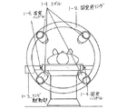
図1、2の様に、単一平面内に4個のコイル(1−1、2−1)を固定用リング(1−2、2−2)上に配列し、中心を空洞としたものを基本器具(リングA)として、2個を対向させ、2つのリングAの穴を通して患者を収容する。それぞれのコイルの組み合わせと間隔、角度を調節して、通電電流、電圧、極性、周波数、波形を制御して、患者体内に磁場を形成して、体内に挿入した器具の誘導を行い、診断、治療といった、医療行為を行う。リングAの間隔をとることで、CT装置や、X線透視装置との干渉を防止する。
リングA内のコイル数は目的にあわせて設定し、また複数の中から使用するものを選択することも可能である。たとえば図1、2の4個のコイルのうち、対向する2個のみをコイルとし、残りを1組のX線透視装置とすれば、磁力による誘導のX線透視での確認と操作が容易となり、またこの形の装置は、CアームX線透視装置のアームを延長し、コイルを装備することで製作できるため普及が容易である。平面に限らずに必要に応じて曲面上に配置することも可能である。コイル数が多ければ、より高度な制御が可能であり、反対に単純な制御であれば、1個のコイルでも可能である。
またリングAを1個単独に使用して、単純な制御を行うことも可能で、リングAを追加するなどリングAを3個以上使用することや、目的に適したコイルを補助コイルとして単独、又複数で追加することで、更に高度な制御を行う。
リングAの様にリング状、枠状としなくても、複数、又は単独のコイルを、患者周囲にたとえば自在アームを使用して配置し、それぞれのコイルの組み合わせと間隔、角度を調節し、通電電流、電圧、極性、周波数、波形を制御して、患者体内に磁場を形成して、体内に挿入した器具の誘導を行い、診断、治療といった、医療行為を行う。間隔を十分にとることで、CT装置や、X線透視装置との干渉を防止する。
コイルに磁性体を組み合わせることで、鉄芯コイルとすれば、磁場強度は5〜10倍となり、高効率化、低消費電力化が可能である。また複数のコイルの鉄芯外側を磁性体で連結した図3、4のような装置においては、患者医療行為を行う外側で鉄芯が連結されるため、周囲に対する漏れ磁束を大幅に減少させることが可能となり、結果として装置全体、部屋全体の磁気シールドを行わなくても漏れ磁束は100分の1程度まで減少する。磁気シールドを追加すれば、1000分の1〜10000分の1まで漏れ磁束は低下し、地磁気レベルまで低下させることが可能である。
医療行為の種類、目的に応じて、連結する鉄芯コイルの組み合わせを選択することで、制御能、磁場強度が向上する。例えば図5、6の様に、対向するコイルを磁性体で連結することで、一組となり制御されるコイルの組数が増えるため、それぞれを単独に制御を行うことで、患者用の空間を十分確保して、高い磁場強度、制御能、操作性の向上が可能である。
図7、8のように、鉄芯コイルの鉄芯をCリング状として、その磁極を患者に向け、患者の周囲に少なくとも一個以上を配置することで、X線透視装置等の装置を併用しつつ、患者周囲に充分な空間が確保されることにより、鉄芯コイルの存在によって医療行為が障害されずに施行可能である。また患者の体軸方向に強い磁場を発生させることが可能であり、磁気シールドを行うことで、漏れ磁束を減少させ通常の医療器具の使用が可能となる。
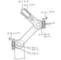
C型アームを単独に用いて患者を収容すれば、一軸方向への磁場を形成することが可能で、その制御およびC型磁気アームの角度、位置の調整によって、三次元的な磁場の形成が可能である。簡易な構造であるため、Cリング状の鉄芯コイルを支持装置に取り付け、回転、上下、伸縮を可能とした図9、10のごときポータブル磁界発生装置では、既存の医療器具、患者の状態、医療手技の種類、タイミングに応じて、自由に磁気装置を使用した、医療行為が可能となる。また磁気シールドを施せば、地磁気レベルまで漏れ磁束を軽減でき、磁気装置の医療領域における幅広い適応が可能である。
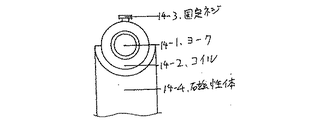
鉄芯コイルを使用することによって、その鉄芯を例えば、コイル内で、ヨークが自由に移動、伸縮可能にし、必要時にたとえば固定ネジで固定することで、図11、12の様に伸縮構造とすれば、患者体内に発生させる磁場の強度、範囲を制御しつつ、併用器具、患者、目的などに対する汎用性を向上することが可能である。また伸縮機構を、磁力を発生するヨークを、別の筒状の磁性体で収容した図13、14の様にすることで、周囲への漏れ磁束を更に軽減し、また周囲機材や医療関係者との干渉を減じ、漏れ磁束を更に低減する事が可能である。また蝶番構造でコイルをささえる図15の様なアーム型とすれば、患者に対してその距離や位置の調節もより自由度が大きく、自在アームとして患者周囲の目的の位置に目的のコイルを配置することもできる。
Cリング状の鉄芯コイルを用いた、図16のごとき磁界発生装置の磁力は、以下のごとく計算される。この際、C型の磁性体ヨークにNターンの励磁巻線を装着し、電流iで励磁するものとする。C型ヨークの磁路長をL2とし、磁界が発生する空隙部分の長さをL1、ヨークの断面積をS1、空隙部分の断面積をS2、ヨークの比透磁率をμとする。
磁気回路の考えにおいて、起磁力Vmと磁束φ、磁気抵抗(リラクタンス)Rmの関係は、
Vm=φ・Rm (1)
となるので、発生磁束φは起磁力Vmと磁気抵抗Rmから算出できる。Nターンの巻線に電流iを流しているので、起磁力はVm=Niであり、磁気抵抗はヨーク部分と空隙部分とにわけて下記のように算出される。ただしここで、μ0は真空の透磁率である。
Rm=L1/(μ0・μ・S1)+L2/(μ0・S2) (2)
これらより、ヨーク、空隙部分に発生する磁束φは、
φ=Vm/Rm=Ni/Rm (3)
と計算できる。
ゆえに、空隙部分に発生する磁界Hは
H=φ/(μ0・S2) (4)
であるから、φに(2),(3)式を代入して、以下のように計算できる。

ここに1200ターンのコイルを巻いて100Aの電流を流すと、発生磁界は約40kA/m(=約5kOe)である。この磁界が、細径のガイドワイアーに装着可能な1mm×1mm×3mmの角柱状希土類磁石に発生させる磁気トルクは、約12g・cmとなる。太径のガイドワイアーに装着可能な2.5mm×2.5mm×10mmの角柱希土類磁石では、その約20倍の磁気トルクが発生し、医療操作に十分な磁気トルクを発生させる事が可能である。
L2: C型ヨークの磁路長
S1: ヨーク断面積
S2: 空隙部分断面積
μ: ヨークの比透磁率
i: 電流
【0006】
【発明の効果】
これまでのCTやX線透視装置との併用が可能となり、患者の体の大きさ、医療手技、必要な器材による当該装置への影響も少ない。磁場の強度、発生範囲も自由に設定可能で、周囲への磁力の影響を著しく低減し、地磁気レベルとすることが可能であるため、使用や導入、適応における自由度が著しく増大する。従来の医療手技においても、必要に応じて容易に磁気応用医療器材の利用が可能となる。また高効率化で低消費電力化が可能で、非常に高い磁場強度を形成することも容易である。
これらを通して、これまで不可能であった医療領域における磁気駆動を含めた磁気装置の、実際的な適用が可能となり、新たな医療手技が開発され、更にこれまで難しかった医療手技がより容易、高精度、高効果、安全に行えるなどの高い効果がある。
【図面の簡単な説明】
【図1】単一平面内に4個のコイルを固定用リング上に配列したリングAの正面図
【図2】単一平面内に4個のコイルを固定用リング上に配列したリングAの側面図
【図3】複数のコイルの鉄芯外側を磁性体で連結した装置の正面図
【図4】複数のコイルの鉄芯外側を磁性体で連結した装置の側面図
【図5】対向した鉄芯コイルを連結した装置の側面図
【図6】対向した鉄芯コイルを連結した装置の正面図
【図7】鉄芯コイルの鉄芯をCリング状とし磁極を患者に向けた装置の正面図
【図8】鉄芯コイルの鉄芯をCリング状とし磁極を患者に向けた装置の側面図
【図9】Cリング状の鉄芯コイルを支持装置に取り付けたポータブル磁界発生装置の側面図
【図10】Cリング状の鉄芯コイルを支持装置に取り付けたポータブル磁界発生装置の正面図
【図11】コイル内のヨークを移動、伸縮可能にして固定ネジで固定した伸縮機構の断面図
【図12】コイル内のヨークを移動、伸縮可能にして固定ネジで固定した伸縮機構の正面図
【図13】磁力を発生するヨークを、別の筒状の磁性体で収容した伸縮機構の断面図
【図14】磁力を発生するヨークを、別の筒状の磁性体で収容した伸縮機構の正面図
【図15】蝶番構造でコイルをささえるアーム型位置調整機構
【図16】Cリング状鉄芯コイルの側面図
【符号の説明】
1−1 コイル 1−2 固定用リング
1−3 リング駆動部 1−4 固定ハンドル
2−1 コイル 2−2 固定用リング
2−3 リング駆動部 2−4 固定ハンドル
3−1 コイル 3−2 磁性体
4−1 コイル 4−2 磁性体
5−1 コイル 5−2 磁性体
6−1 コイル 6−2 磁性体
7−1 鉄芯コイル 8−1 鉄芯コイル
9−1 Cリング鉄芯状コイル
9−2 スパーギヤ 9−3 ピニオンギヤ
9−4 角度調整手段 9−5 スパーギヤ
9−6 ピニオンギヤ 9−7 駆動手段
9−8 スパイラルギヤ 9−9 ピニオンギヤ
9−10 ピニオンギヤ
9−11 ウォーム&ウォームホイール
9−12 ウォームホイール 9−13 ウォームギヤ
9−14 カウンターウェイト
10−1 Cリング状鉄芯コイル
10−2 スパーギヤ 10−3 ピニオンギヤ
10−4 カウンターウェイト
10−5 スパーギヤ
11−1 ヨーク 11−2 コイル
11−3 磁性体 11−4 固定ネジ
12−1 ヨーク 12−2 コイル
12−3 磁性体 12−4 固定ネジ
13−1 ヨーク 13−2 コイル
13−3 固定ネジ 13−4 磁性体
13−5 ハンドル
14−1 ヨーク 14−2 コイル
14−3 固定ネジ 14−4 磁性体
15−1 ヨーク 15−2 コイル
15−3 ハンドル 15−4 ウォーム
15−5 ウォームホイール 15−6 ウォームホイール
15−7 ウォーム 15−8 ハンドル
L1 磁界が発生する空隙部分の長さ
L2 C型ヨークの磁路長
S1 ヨーク断面積
S2 空隙部分断面積
μ ヨークの透磁率
i 電流比
N コイルの巻数[0001]
BACKGROUND OF THE INVENTION
The invention places and energizes an instrument that reacts to the magnetic force inserted in the body by placing at least one coil around the patient, generating and controlling a magnetic field in the patient's body. Medical equipment that performs medical actions such as diagnosis and treatment.
[0002]
[Prior art]
It is not easy to generate an effective magnetic force only by applying a magnet from the body surface in order to pull a medical device equipped with a magnet in the body, and even if a sufficient magnetic force can be applied, a distance of 3 Due to the principle of a magnetic field that is inversely proportional to the power, it is almost impossible to guide it in a free position in the body lumen, and it has not been practically used in the medical field so far.
In order to generate a parallel magnetic field that is easy to guide the instrument, it was necessary to combine large air-core coils in a cross-beam shape and accommodate the patient inside. However, since the entire device becomes enormous, it interferes with the X-ray fluoroscopy device and CT necessary for checking the position of the instrument in the body, and since the coil itself blocks the X-ray, the position of the instrument in the body cannot be confirmed. The electric power for generating the magnetic field is large, and the leakage magnetic flux to the surroundings is large, which has an influence on the surrounding equipment, and it is very difficult to put it into practical use including safety.
In addition, during regular medical practice, even if the assistance of a magnetic device is necessary and the application is thought to promote the procedure, the device is not versatile, so the laboratory, the procedure, the patient, the timing of the test, etc. It was difficult to apply easily and temporarily as needed.
For the above reasons, actual application of magnetic devices in the medical field has been impossible until now.
[0003]
[Problems to be solved by the invention]
The medical device using magnetism can be used or easily used with a conventional medical device, and effective use of magnetism including high-level guidance is performed. In addition, depending on the purpose, the device is reduced in size, increased in efficiency, reduced in power consumption, and reduced in magnetic flux leakage, thereby improving the versatility in actual medicine and making it a practical medical device.
[0004]
[Means for Solving the Problems]
In order to solve the above-described problem, in the medical magnetic device according to the present invention, a plurality of support members that are disposed so as to surround an object and face each other so as to prevent interference with other devices are respectively supported. A plurality of coils supported by the member and connected to form a magnetic field in the object and to define a flow of magnetic flux and reduce leakage of the magnetic flux, and control the magnetic field formed by the coil Thus, the magnetic material arranged in the object is guided. Here, the support member preferably has a magnetic material.
At least one air core or iron core coil is placed outside the patient's body according to the interval, and the strength, phase, and frequency of each coil current are controlled, and the strength according to the purpose. A magnetic field of action and direction is generated in the patient's body, and guidance, diagnosis, and treatment of instruments that respond to the magnetic force inserted in the body are performed.
(1) At least one or more coils are arranged on a plane or a curved surface, and these coils are made to face each other or used alone to generate a magnetic field in the patient's body.
(2) On the opposite side of the iron core coil that generates the intended magnetic field, it is connected to the iron core of another iron core coil to reduce leakage flux to the surroundings.
By using a device having the basic coil arrangement and structure as described above alone or in combination, medical treatment is performed via a device that reacts to magnetism in the patient's body.
[0005]
DETAILED DESCRIPTION OF THE INVENTION
As shown in FIGS. 1 and 2, four coils (1-1, 2-1) are arranged on a fixing ring (1-2, 2-2) in a single plane and the center is a cavity. Is the basic instrument (Ring A), with the two facing each other, and the patient is accommodated through the holes in the two Rings A. Adjust the combination, spacing, and angle of each coil to control the energization current, voltage, polarity, frequency, and waveform, create a magnetic field in the patient body, guide the instrument inserted in the body, diagnose, Perform medical practices such as treatment. By taking the interval of the ring A, interference with the CT apparatus and the X-ray fluoroscopic apparatus is prevented.
The number of coils in the ring A can be set in accordance with the purpose, and a plurality of coils to be used can be selected. For example, if only two of the four coils shown in FIGS. 1 and 2 are opposed to each other and the rest is a set of X-ray fluoroscopy devices, confirmation and operation by magnetic X-ray fluoroscopy can be facilitated. In addition, this type of device is easy to spread because it can be manufactured by extending the arm of a C-arm X-ray fluoroscopy device and mounting a coil. It is also possible to arrange on a curved surface as needed without being limited to a flat surface. If the number of coils is large, more advanced control is possible, and conversely simple control is also possible with a single coil.
Also, it is possible to perform simple control by using one ring A alone, using three or more rings A such as adding ring A, or using a coil suitable for the purpose as an auxiliary coil, Moreover, by adding a plurality, more advanced control is performed.
Even if it is not ring-shaped or frame-shaped like ring A, multiple or single coils are placed around the patient using, for example, a free arm, and the combination, spacing, and angle of each coil are adjusted to energize By controlling the current, voltage, polarity, frequency, and waveform, a magnetic field is formed in the patient body, the instrument inserted in the body is guided, and medical treatment such as diagnosis and treatment is performed. Interference with the CT apparatus and the X-ray fluoroscopic apparatus is prevented by taking a sufficient interval.
By combining a magnetic material with the coil, the magnetic field strength is 5 to 10 times higher if the iron core coil is used, and higher efficiency and lower power consumption are possible. Moreover, in the apparatus as shown in FIGS. 3 and 4 in which the outer sides of the iron cores of a plurality of coils are connected with a magnetic material, the iron cores are connected on the outer side for performing the medical treatment of the patient. As a result, the magnetic flux leakage can be reduced to about 1/100 without performing magnetic shielding for the entire apparatus and the entire room. If a magnetic shield is added, the leakage flux will be reduced to 1/1000 to 1/10000, and it can be reduced to the geomagnetic level.
Control ability and magnetic field strength are improved by selecting a combination of iron core coils to be connected according to the type and purpose of medical practice. For example, as shown in FIGS. 5 and 6, by connecting the opposing coils with a magnetic material, the number of coils to be controlled increases as one set. Sufficiently secured, high magnetic field strength, controllability, and operability can be improved.
As shown in Figs. 7 and 8, the iron core of the iron core coil is shaped like a C ring, the magnetic poles are directed to the patient, and at least one or more devices are placed around the patient. On the other hand, by ensuring a sufficient space around the patient, the medical action can be performed without being hindered by the presence of the iron core coil. Further, it is possible to generate a strong magnetic field in the body axis direction of the patient, and by performing a magnetic shield, the leakage magnetic flux can be reduced and a normal medical instrument can be used.
If a patient is accommodated using a C-type arm alone, it is possible to form a magnetic field in a uniaxial direction. By controlling the angle and position of the C-type magnetic arm, a three-dimensional magnetic field can be formed. Is possible. The portable magnetic field generator as shown in FIGS. 9 and 10 in which a C-ring-shaped iron core coil is attached to the support device and can be rotated, moved up and down, can be expanded and contracted because of its simple structure. Depending on the type and timing of the medical procedure, it is possible to perform medical practice using the magnetic device freely. Moreover, if a magnetic shield is provided, the leakage magnetic flux can be reduced to the geomagnetic level, and the magnetic device can be widely applied in the medical field.
By using an iron core coil, the iron core can be moved and expanded freely in the coil, for example, and fixed with a fixing screw when necessary, for example, as shown in FIGS. If so, it is possible to improve the versatility of the combined device, patient, purpose, etc. while controlling the intensity and range of the magnetic field generated in the patient. The telescopic mechanism is made as shown in FIGS. 13 and 14 in which the yoke that generates magnetic force is accommodated by another cylindrical magnetic body, thereby further reducing the leakage magnetic flux to the surroundings, and the surrounding equipment and medical personnel. It is possible to further reduce the leakage magnetic flux. If the arm type as shown in FIG. 15 is used to hold the coil with a hinge structure, the distance and position can be adjusted more freely with respect to the patient, and the desired coil is placed at the desired position around the patient as a free arm. You can also
The magnetic force of a magnetic field generator as shown in FIG. 16 using a C-ring iron core coil is calculated as follows. At this time, it is assumed that an N-turn exciting winding is mounted on a C-type magnetic yoke and excited by a current i. A magnetic path length of the C-type yokes and L 2, and L 1 the length of the gap portion of the magnetic field is generated, S 1 a cross-sectional area of the yoke, S 2 a cross-sectional area of the gap portion, the relative permeability of the yoke μ To do.
In the idea of a magnetic circuit, the relationship between magnetomotive force Vm, magnetic flux φ, and magnetic resistance (reluctance) Rm is
Vm = φ · Rm (1)
Therefore, the generated magnetic flux φ can be calculated from the magnetomotive force Vm and the magnetic resistance Rm. Since the current i flows through the N-turn winding, the magnetomotive force is Vm = Ni, and the magnetoresistance is calculated as follows by dividing the yoke portion and the gap portion. Where μ 0 is the vacuum permeability.
Rm = L 1 / (μ 0 · μ · S 1) + L 2 / (μ 0 · S 2) (2)
From these, the magnetic flux φ generated in the yoke and the gap is
φ = Vm / Rm = Ni / Rm (3)
Can be calculated.
Therefore, the magnetic field H generated in the gap is H = φ / (μ 0 · S 2 ) (4)
Therefore, by substituting the equations (2) and (3) into φ, it can be calculated as follows.
When a coil of 1200 turns is wound around this and a current of 100 A is passed, the generated magnetic field is about 40 kA / m (= about 5 kOe). The magnetic torque generated by this magnetic field in a 1 mm × 1 mm × 3 mm prismatic rare earth magnet that can be mounted on a thin guide wire is about 12 g · cm. A 2.5 mm x 2.5 mm x 10 mm prismatic rare earth magnet that can be attached to a large-diameter guide wire generates about 20 times the magnetic torque, and can generate sufficient magnetic torque for medical operations. .
【The invention's effect】
It can be used in combination with conventional CT and X-ray fluoroscopy devices, and there is little influence on the device due to the size of the patient's body, medical procedures, and necessary equipment. The strength and generation range of the magnetic field can be set freely, the influence of the magnetic force on the surroundings can be remarkably reduced, and the level of geomagnetism can be achieved, so the degree of freedom in use, introduction, and adaptation is significantly increased. Even in conventional medical procedures, it is possible to easily use magnetic applied medical equipment as necessary. In addition, high efficiency and low power consumption are possible, and it is easy to form a very high magnetic field strength.
Through these, magnetic devices including magnetic drive in the medical field, which was impossible until now, can be practically applied, new medical techniques have been developed, and medical techniques that have been difficult until now are easier and more sophisticated. There are high effects such as accuracy, high effect, and safety.
[Brief description of the drawings]
FIG. 1 is a front view of a ring A in which four coils are arranged on a fixing ring in a single plane. FIG. 2 is a front view of the ring A in which four coils are arranged on a fixing ring in a single plane. Side view [Fig. 3] Front view of a device in which the outer sides of a plurality of coils are connected with a magnetic material [Fig. 4] Side view of a device in which the outer sides of a plurality of coils are connected with a magnetic material [Fig. Side view of the device connecting the iron core coils [Fig. 6] Front view of the device connecting the iron coils facing each other [Fig. 7] Front view of the device with the iron core of the iron core coil shaped like a C-ring and the magnetic pole facing the patient FIG. 8 is a side view of an apparatus in which the iron core of the iron core coil has a C-ring shape and the magnetic pole faces the patient. FIG. 9 is a side view of a portable magnetic field generator in which the C-ring iron core coil is attached to a support device. FIG. 10 is a perspective view of a portable magnetic field generator having a C-ring iron core coil attached to a support device. Fig. 11 is a cross-sectional view of a telescopic mechanism in which the yoke in the coil can be moved and expanded and fixed with a fixing screw. Fig. 12 is a front view of the telescopic mechanism in which the yoke in the coil can be moved and expanded and fixed with a fixing screw. FIG. 13 is a cross-sectional view of an expansion / contraction mechanism in which a yoke generating magnetic force is accommodated by another cylindrical magnetic body. FIG. 14 is an expansion / contraction mechanism in which a yoke generating magnetic force is accommodated by another cylindrical magnetic body. [Fig. 15] Arm type position adjustment mechanism that supports the coil with a hinge structure [Fig. 16] Side view of C-ring iron core coil [Explanation of symbols]
1-1 Coil 1-2 Ring for fixing 1-3 Ring driving unit 1-4 Fixed handle 2-1 Coil 2-2 Ring for fixing 2-3 Ring driving unit 2-4 Fixed handle 3-1 Coil 3-2 Magnetic Body 4-1 Coil 4-2 Magnetic body 5-1 Coil 5-2 Magnetic body 6-1 Coil 6-2 Magnetic body 7-1 Iron core coil 8-1 Iron core coil 9-1 C-ring iron core coil 9 -2 Spur gear 9-3 Pinion gear 9-4 Angle adjusting means 9-5 Spur gear 9-6 Pinion gear 9-7 Drive means 9-8 Spiral gear 9-9 Pinion gear 9-10 Pinion gear 9-11 Worm & worm wheel 9-12 Worm Wheel 9-13 Worm gear 9-14 Counterweight 10-1 C-ring iron core coil 10-2 Spur gear 10-3 Pinion gear 10-4 Counter 8-10 Spur gear 11-1 Yoke 11-2 Coil 11-3 Magnetic body 11-4 Fixing screw 12-1 Yoke 12-2 Coil 12-3 Magnetic body 12-4 Fixing screw 13-1 Yoke 13-2 Coil 13 -3 fixing screw 13-4 magnetic body 13-5 handle 14-1 yoke 14-2 coil 14-3 fixing screw 14-4 magnetic body 15-1 yoke 15-2 coil 15-3 handle 15-4 worm 15-5 the worm wheel 15-6 worm wheel 15-7 worm 15-8 handles L 1 of the air gap portion in which the magnetic field is generated length L 2 C type yoke magnetic path length S 1 yoke sectional area S 2 air gap cross sections μ yoke Toru Magnetic susceptibility i Current ratio N Number of coil turns
Claims (2)
それぞれ前記支持部材に支持され、前記対象物内に磁場を形成し、かつ、磁束の流れを規定し磁束の漏れを減少させるように連結されている複数のコイルと、を備え、
前記コイルの形成する磁場を制御することによって、前記対象物内に配置した磁性体の誘導を行うことを特徴とする医療用磁気装置。A plurality of support members arranged so as to surround the object and facing each other at a predetermined interval so as to prevent interference with other devices ;
A plurality of coils each supported by the support member, connected to form a magnetic field in the object , and to define a flow of magnetic flux and reduce leakage of the magnetic flux ,
A medical magnetic apparatus characterized in that a magnetic body disposed in the object is guided by controlling a magnetic field formed by the coil.
Priority Applications (1)
| Application Number | Priority Date | Filing Date | Title |
|---|---|---|---|
| JP2001071241A JP3632073B2 (en) | 2001-02-07 | 2001-02-07 | Medical magnetic device |
Applications Claiming Priority (1)
| Application Number | Priority Date | Filing Date | Title |
|---|---|---|---|
| JP2001071241A JP3632073B2 (en) | 2001-02-07 | 2001-02-07 | Medical magnetic device |
Publications (2)
| Publication Number | Publication Date |
|---|---|
| JP2002233575A JP2002233575A (en) | 2002-08-20 |
| JP3632073B2 true JP3632073B2 (en) | 2005-03-23 |
Family
ID=18928993
Family Applications (1)
| Application Number | Title | Priority Date | Filing Date |
|---|---|---|---|
| JP2001071241A Expired - Fee Related JP3632073B2 (en) | 2001-02-07 | 2001-02-07 | Medical magnetic device |
Country Status (1)
| Country | Link |
|---|---|
| JP (1) | JP3632073B2 (en) |
Cited By (1)
| Publication number | Priority date | Publication date | Assignee | Title |
|---|---|---|---|---|
| WO2009119236A1 (en) * | 2008-03-26 | 2009-10-01 | テルモ株式会社 | Treatment apparatus |
Families Citing this family (17)
| Publication number | Priority date | Publication date | Assignee | Title |
|---|---|---|---|---|
| JP4147315B2 (en) * | 2002-09-13 | 2008-09-10 | Hoya株式会社 | Magnetic anchor remote guidance system |
| CN100393378C (en) * | 2003-11-17 | 2008-06-11 | 陈克雄 | Holographic dynamic equilibrium positioning therapeutic equipments of TCM |
| JP2005319274A (en) * | 2004-04-06 | 2005-11-17 | Pentax Corp | Grip device for endoscope, and magnetic anchor remote guide system |
| JPWO2006035550A1 (en) * | 2004-09-28 | 2008-05-15 | 国立大学法人大阪大学 | Three-dimensional guidance apparatus and method, and drug delivery system |
| WO2007029139A2 (en) * | 2005-09-08 | 2007-03-15 | Philips Intellectual Property & Standards Gmbh | Magnetic tracking system for an imaging system |
| WO2007037380A1 (en) * | 2005-09-30 | 2007-04-05 | Hitachi Metals, Ltd. | Magnetic field control method and magnetic field generation device |
| JP2007151605A (en) * | 2005-11-30 | 2007-06-21 | Mitsuo Ochi | Magnetic induction device and guide system of magnetic complex |
| JP4671287B2 (en) * | 2005-12-22 | 2011-04-13 | 独立行政法人国立がん研究センター | Magnetic generator |
| JP2009539511A (en) * | 2006-06-14 | 2009-11-19 | エンジョイ スポレチノスト エス ルチェニム オメゼニム | A device that attenuates cellular metabolism |
| CN100463706C (en) * | 2007-03-30 | 2009-02-25 | 天津大学 | Magnetic medicine guider |
| WO2010041714A1 (en) * | 2008-10-10 | 2010-04-15 | 学校法人自治医科大学 | Surgery system for endoscopic submucosal dissection (esd) and surgery method |
| CN101884824A (en) * | 2010-07-02 | 2010-11-17 | 华中科技大学 | Three-dimension scanning large gradient electromagnetic guiding device |
| EP3206577A1 (en) | 2014-10-15 | 2017-08-23 | Vincent Suzara | Magnetic field structures, field generators, navigation and imaging for untethered robotic device enabled medical procedure |
| AT517737B1 (en) * | 2015-10-02 | 2018-07-15 | Pontemed Ag | Magnetic stimulation device |
| EP3499529A4 (en) * | 2016-08-10 | 2020-04-29 | IUCF-HYU (Industry-University Cooperation Foundation Hanyang University) | Magnetic field control system |
| JP6942340B2 (en) * | 2017-08-04 | 2021-09-29 | 国立大学法人広島大学 | Magnetic field induction device |
| WO2019154837A1 (en) * | 2018-02-06 | 2019-08-15 | Stimit Ag | Electro-magnetic induction device and method of activating a target tissue |
-
2001
- 2001-02-07 JP JP2001071241A patent/JP3632073B2/en not_active Expired - Fee Related
Cited By (1)
| Publication number | Priority date | Publication date | Assignee | Title |
|---|---|---|---|---|
| WO2009119236A1 (en) * | 2008-03-26 | 2009-10-01 | テルモ株式会社 | Treatment apparatus |
Also Published As
| Publication number | Publication date |
|---|---|
| JP2002233575A (en) | 2002-08-20 |
Similar Documents
| Publication | Publication Date | Title |
|---|---|---|
| JP3632073B2 (en) | Medical magnetic device | |
| JP6791928B2 (en) | Systems and methods for radiation therapy by magnetic resonance imaging | |
| US6201394B1 (en) | MRI apparatus | |
| US8958864B2 (en) | Combined radiation therapy and magnetic resonance unit | |
| US6437571B1 (en) | MRI apparatus | |
| JP4826929B2 (en) | Magnetic field generator | |
| KR20210013563A (en) | B0 magnet methods and devices for magnetic resonance imaging system | |
| WO2001009633A3 (en) | Magnetic resonance imaging controlled by the position of a moveable rf coil | |
| US8487269B2 (en) | Combined radiation therapy and magnetic resonance unit | |
| US20130197351A1 (en) | Beam deflection arrangement within a combined radiation therapy and magnetic resonance unit | |
| JP2000201902A (en) | Adjustable magnet for magnetic resonance imaging | |
| US20130046169A1 (en) | Mri-guided nanoparticle cancer therapy apparatus and methodology | |
| JP2002078701A (en) | Medical examination device | |
| JP2006068501A (en) | Magnetic induction medical system | |
| JPH11128204A (en) | Method to navigate magnetic object and mr equipment | |
| JP5933567B2 (en) | Medical equipment | |
| JP2007175188A (en) | System of guiding capsule type medical apparatus | |
| US20130109920A1 (en) | Arrangement and method for navigating an endoscopic capsule | |
| JP5226319B2 (en) | Arrangement and method for determining the spatial distribution of magnetic particles | |
| KR20210124562A (en) | Movable Apparatus For Controlling Micro/Nano Robot | |
| JPH1028682A (en) | Magnet device for magnetic resonance device for diagnosis | |
| CN109330684A (en) | A kind of magnetic navigation device and magnetic navigation method for cerebrovascular interventional therapy | |
| EP4005519A1 (en) | Magnetic drive system and microrobot control method using same | |
| JP2008517673A (en) | Apparatus and method for image guided cannula or needle insertion and removal | |
| KR102260162B1 (en) | Apparatus for Controlling Micro Robot |
Legal Events
| Date | Code | Title | Description |
|---|---|---|---|
| A131 | Notification of reasons for refusal |
Free format text: JAPANESE INTERMEDIATE CODE: A131 Effective date: 20040601 |
|
| A521 | Written amendment |
Free format text: JAPANESE INTERMEDIATE CODE: A523 Effective date: 20040716 |
|
| TRDD | Decision of grant or rejection written | ||
| A01 | Written decision to grant a patent or to grant a registration (utility model) |
Free format text: JAPANESE INTERMEDIATE CODE: A01 Effective date: 20041124 |
|
| R150 | Certificate of patent or registration of utility model |
Free format text: JAPANESE INTERMEDIATE CODE: R150 |
|
| S111 | Request for change of ownership or part of ownership |
Free format text: JAPANESE INTERMEDIATE CODE: R313111 |
|
| R350 | Written notification of registration of transfer |
Free format text: JAPANESE INTERMEDIATE CODE: R350 |
|
| LAPS | Cancellation because of no payment of annual fees |