JP3631442B2 - Array storage system - Google Patents
Array storage system Download PDFInfo
- Publication number
- JP3631442B2 JP3631442B2 JP2001134690A JP2001134690A JP3631442B2 JP 3631442 B2 JP3631442 B2 JP 3631442B2 JP 2001134690 A JP2001134690 A JP 2001134690A JP 2001134690 A JP2001134690 A JP 2001134690A JP 3631442 B2 JP3631442 B2 JP 3631442B2
- Authority
- JP
- Japan
- Prior art keywords
- storage
- logical
- identifier
- logical volume
- storage devices
- Prior art date
- Legal status (The legal status is an assumption and is not a legal conclusion. Google has not performed a legal analysis and makes no representation as to the accuracy of the status listed.)
- Expired - Lifetime
Links
Images


Classifications
-
- G—PHYSICS
- G11—INFORMATION STORAGE
- G11C—STATIC STORES
- G11C29/00—Checking stores for correct operation ; Subsequent repair; Testing stores during standby or offline operation
- G11C29/70—Masking faults in memories by using spares or by reconfiguring
- G11C29/88—Masking faults in memories by using spares or by reconfiguring with partially good memories
-
- G—PHYSICS
- G06—COMPUTING OR CALCULATING; COUNTING
- G06F—ELECTRIC DIGITAL DATA PROCESSING
- G06F11/00—Error detection; Error correction; Monitoring
- G06F11/006—Identification
-
- G—PHYSICS
- G06—COMPUTING OR CALCULATING; COUNTING
- G06F—ELECTRIC DIGITAL DATA PROCESSING
- G06F11/00—Error detection; Error correction; Monitoring
- G06F11/22—Detection or location of defective computer hardware by testing during standby operation or during idle time, e.g. start-up testing
- G06F11/2289—Detection or location of defective computer hardware by testing during standby operation or during idle time, e.g. start-up testing by configuration test
-
- G—PHYSICS
- G06—COMPUTING OR CALCULATING; COUNTING
- G06F—ELECTRIC DIGITAL DATA PROCESSING
- G06F3/00—Input arrangements for transferring data to be processed into a form capable of being handled by the computer; Output arrangements for transferring data from processing unit to output unit, e.g. interface arrangements
- G06F3/06—Digital input from, or digital output to, record carriers, e.g. RAID, emulated record carriers or networked record carriers
- G06F3/0601—Interfaces specially adapted for storage systems
- G06F3/0602—Interfaces specially adapted for storage systems specifically adapted to achieve a particular effect
- G06F3/0604—Improving or facilitating administration, e.g. storage management
- G06F3/0607—Improving or facilitating administration, e.g. storage management by facilitating the process of upgrading existing storage systems, e.g. for improving compatibility between host and storage device
-
- G—PHYSICS
- G06—COMPUTING OR CALCULATING; COUNTING
- G06F—ELECTRIC DIGITAL DATA PROCESSING
- G06F3/00—Input arrangements for transferring data to be processed into a form capable of being handled by the computer; Output arrangements for transferring data from processing unit to output unit, e.g. interface arrangements
- G06F3/06—Digital input from, or digital output to, record carriers, e.g. RAID, emulated record carriers or networked record carriers
- G06F3/0601—Interfaces specially adapted for storage systems
- G06F3/0628—Interfaces specially adapted for storage systems making use of a particular technique
- G06F3/0629—Configuration or reconfiguration of storage systems
- G06F3/0632—Configuration or reconfiguration of storage systems by initialisation or re-initialisation of storage systems
-
- G—PHYSICS
- G06—COMPUTING OR CALCULATING; COUNTING
- G06F—ELECTRIC DIGITAL DATA PROCESSING
- G06F3/00—Input arrangements for transferring data to be processed into a form capable of being handled by the computer; Output arrangements for transferring data from processing unit to output unit, e.g. interface arrangements
- G06F3/06—Digital input from, or digital output to, record carriers, e.g. RAID, emulated record carriers or networked record carriers
- G06F3/0601—Interfaces specially adapted for storage systems
- G06F3/0628—Interfaces specially adapted for storage systems making use of a particular technique
- G06F3/0629—Configuration or reconfiguration of storage systems
- G06F3/0634—Configuration or reconfiguration of storage systems by changing the state or mode of one or more devices
-
- G—PHYSICS
- G06—COMPUTING OR CALCULATING; COUNTING
- G06F—ELECTRIC DIGITAL DATA PROCESSING
- G06F3/00—Input arrangements for transferring data to be processed into a form capable of being handled by the computer; Output arrangements for transferring data from processing unit to output unit, e.g. interface arrangements
- G06F3/06—Digital input from, or digital output to, record carriers, e.g. RAID, emulated record carriers or networked record carriers
- G06F3/0601—Interfaces specially adapted for storage systems
- G06F3/0628—Interfaces specially adapted for storage systems making use of a particular technique
- G06F3/0653—Monitoring storage devices or systems
-
- G—PHYSICS
- G06—COMPUTING OR CALCULATING; COUNTING
- G06F—ELECTRIC DIGITAL DATA PROCESSING
- G06F3/00—Input arrangements for transferring data to be processed into a form capable of being handled by the computer; Output arrangements for transferring data from processing unit to output unit, e.g. interface arrangements
- G06F3/06—Digital input from, or digital output to, record carriers, e.g. RAID, emulated record carriers or networked record carriers
- G06F3/0601—Interfaces specially adapted for storage systems
- G06F3/0668—Interfaces specially adapted for storage systems adopting a particular infrastructure
- G06F3/0671—In-line storage system
- G06F3/0683—Plurality of storage devices
- G06F3/0689—Disk arrays, e.g. RAID, JBOD
-
- G—PHYSICS
- G11—INFORMATION STORAGE
- G11B—INFORMATION STORAGE BASED ON RELATIVE MOVEMENT BETWEEN RECORD CARRIER AND TRANSDUCER
- G11B19/00—Driving, starting, stopping record carriers not specifically of filamentary or web form, or of supports therefor; Control thereof; Control of operating function ; Driving both disc and head
- G11B19/02—Control of operating function, e.g. switching from recording to reproducing
- G11B19/12—Control of operating function, e.g. switching from recording to reproducing by sensing distinguishing features of or on records, e.g. diameter end mark
-
- G—PHYSICS
- G11—INFORMATION STORAGE
- G11B—INFORMATION STORAGE BASED ON RELATIVE MOVEMENT BETWEEN RECORD CARRIER AND TRANSDUCER
- G11B20/00—Signal processing not specific to the method of recording or reproducing; Circuits therefor
- G11B20/10—Digital recording or reproducing
- G11B20/18—Error detection or correction; Testing, e.g. of drop-outs
- G11B20/1816—Testing
-
- G—PHYSICS
- G06—COMPUTING OR CALCULATING; COUNTING
- G06F—ELECTRIC DIGITAL DATA PROCESSING
- G06F11/00—Error detection; Error correction; Monitoring
- G06F11/07—Responding to the occurrence of a fault, e.g. fault tolerance
- G06F11/14—Error detection or correction of the data by redundancy in operations
- G06F11/1402—Saving, restoring, recovering or retrying
- G06F11/1415—Saving, restoring, recovering or retrying at system level
Landscapes
- Engineering & Computer Science (AREA)
- Theoretical Computer Science (AREA)
- General Engineering & Computer Science (AREA)
- Physics & Mathematics (AREA)
- General Physics & Mathematics (AREA)
- Human Computer Interaction (AREA)
- Quality & Reliability (AREA)
- Computer Hardware Design (AREA)
- Signal Processing (AREA)
- Information Retrieval, Db Structures And Fs Structures Therefor (AREA)
Abstract
Description
【0001】
【産業上の利用分野】
本発明は、アレイ記憶システムに係り、特に、論理的ボリュームを構成する複数の記憶デバイスを含む記憶デバイスアレイにおいて各記憶デバイスがその論理的ボリュームの正しいメンバーであるか否かを決定するアレイコントロールモジュールを備えたアレイ記憶システムに関する。
以下の説明では、記憶装置を記憶デバイスとも称する。
【0002】
【従来の技術】
大規模な周辺装置としての記憶システムは、数多くの業務および技術へのソフトウエアの適用に対して有利である。かかるシステムの1つの形態においては、記憶装置アレイを協同して定める多数の独立した記憶装置に対して記憶されるべきデータを分布させることによって、記憶が達成される。かかる個々の記憶装置は、他の装置の中で、磁気的および光学的ディスクの駆動装置を含みうる。かかる記憶システムは大きな記憶容量を有している。ホストシステムとともに、これらの記憶システムは高いデータ伝送速度に寄与している。データの信頼度もまた記憶装置アレイを用いることにより達成される。
【0003】
大きな記憶容量は、例えば5.25インチの磁気ディスクの駆動装置のような、多数の比較的安価な記憶装置を用いることによって達成される。高いデータ伝送速度は、個々の記憶装置が1つ又はそれ以上の論理的ボリューム又は集団にグループ化されるようにシステムを形成することによって達成される。論理的ボリュームは、それが多数の物理的に独立した記憶装置で構成されていても、該ホストシステムには単一の大規模な記憶ユニットとして現れる。該記憶装置アレイは典型的には、1つの論理的ボリューム内でのすべての記憶装置が、データ伝送において同時に関連させられうるようにするためのハードウエアとソフトウエアとを含んでいる。すなわち各記憶装置は、該論理的ボリュームへの読み書きが該論理的ボリューム内での各記憶装置への読み書きによって達成されるような唯一のデータ接続部を有している。このことは、大量のデータが該記憶装置アレイから迅速に読出され又は該記憶装置アレイに迅速に書込まれることを許容する。高いデータの信頼度は、パリティ情報の使用のような、冗長的な記憶データに対するハードウエア素子およびソフトウエア処理を、故障した記憶装置に対する置換体として使用されうる1つ又はそれ以上の特別な記憶装置とともに利用することによって達成されうる。故障した装置でのデータは、該故障した装置が置換されるまで、パリティ情報を用いることによって再構成され、置換した記憶装置に転送される。
【0004】
記憶装置アレイと関連して生ずる要求は、各論理的ボリュームにおける正しい記憶装置の順序又は配列が知られ、かつ維持されなければならないことである。該記憶装置アレイは、ホストシステムによってほん訳しうるデータの単一の流れと、論理的ボリュームからの又は論理的ボリュームへの多重の並列的なデータの流れとの間での変換において、記憶装置のこの順序又はシーケンスを使用する。記憶装置のこの順序付けは、記憶装置アレイから再生されるデータが、論理的ボリュームにおける記憶装置からの並列的なデータ転送を介して、ホストシステムで受け入れ可能な情報の単一の流れに変換されることを許容する。
【0005】
個々の記憶装置の置換が必要となりうることから、発生可能でありかつ補償されなければならない多数のシステム保全上の事態が存在する。例えば、1つの論理的ボリュームの一部である記憶装置が偶然に他の論理的ボリューム内に置かれる可能性があり、この場合には該1つの論理的ボリューム内のデータを読出しえなくする。他の例としては、1つの論理的ボリューム内での記憶装置が不正に変換され、その結果、該記憶装置によって供給されるデータが正しいデータ接続部を介して受け入れられなくなり、したがって正しく変換されえない。より特定的には、連続的に転送されたデータバイトが別のディスクに記憶されることが知られている。例えば固定された大きさのデータブロックに対して、バイト1はディスク1に記憶され、バイト2はディスク2に記憶され、バイトnはディスクnに記憶され、バイト(n+1)はディスク1などに記憶される。多重のディスクからの記憶データを正しく再集するためには、分配されたデータを有する同じディスクがアクセスされることが重大である。もし例えばディスク2が、ディスク2の記憶データを有していない他のディスクによって置換されたならば、かかるディスクからの異なったデータによってはデータが正確に再集されえないという問題点が生ずる。同様に、もしディスク1と2の物理的位置および接続が切り換えられたならば、該データは正確には再集されえない。
【0006】
【発明が解決しようとする課題】
かかる問題は、記憶装置アレイにおける各記憶装置が正しい位置(ロケーション)に置かれているかどうかを自動的に決定するためのメカニズムが欠如していることに起因して発生する。
かかる技術的背景にもとづいて、本発明は、上記したアレイ記憶装置が論理的にグループ化され、かつ各論理的ボリューム内で正しい整列状態にあるという確認がなされうるような処理手順をそなえさせるようにしたものである。
【0007】
【課題を解決するための手段】
かかる課題を解決するために本発明においては、各記憶デバイスが記憶デバイスアレイ内において正しい物理的位置にあることを確認するためのアレイコントロールモジュールを備えたアレイ記憶システムが提供される。すなわち、各記憶デバイスが、その所属する論理的ボリュームに対して正しい物理的位置に設置されているかどうかの決定がなされる。本発明はディスク駆動装置に対しての適用性を有しているが、他の記憶装置とも関連させうる。
【0008】
すなわち、本発明により提供されるものは、それぞれ異なるデバイス識別子を格納する複数の記憶デバイスと、
複数の記憶デバイスに対して、記憶情報の読み出し又は書込みを指示するアレイコントロールモジュールと、を有し、
複数の記憶デバイスとアレイコントロールモジュールとは、取り外し可能に接続され、
アレイコントロールモジュールは、複数の記憶デバイスの一部または全部を一つの論理的ボリュームとして管理し、更に、論理的ボリュームを構成する複数の記憶デバイスに記憶情報を分散して格納し又は論理的ボリュームを構成する複数の記憶デバイスに分散して格納されている記憶情報を読み出して結合するアレイ記憶システムであって、
複数の記憶デバイスは、論理的ボリュームを構成する複数の記憶デバイスに格納されているデバイス識別子と、論理的ボリュームを構成する各記憶デバイスの位置関係とを関連付けた論理的識別子を有し、
論理的ボリュームを構成すべき各記憶デバイスの中に、その論理的ボリュームを構成する記憶デバイスではないものが含まれていることを、デバイス識別子と、論理的識別子から得られるデバイス識別子とを比較することにより決定する決定手段と、
決定手段が、一つの論理的ボリュームの中に論理的ボリュームを構成すべきでない記憶デバイスが含まれていることを決定した場合にその事象を通報する通報手段と、
を備えてなるアレイ記憶システムである。
記憶装置の各論理的ボリュームに対して、論理的識別子(logical identifier)が生成され、各記憶装置に記憶される。このことを行うために、本発明では各記憶装置と単一的にかつ永久的に関連付けられるデバイス識別子(device identifier )が使用される。デバイス識別子は記憶装置(記憶デバイス)から読出されうる。好適な実施例においては、デバイス識別子は、既知の位置において記憶されている記憶装置のシリアル番号である。ある与えられた論理的ボリュームに対して、論理的識別子はそのボリュームに対する個々のデバイス識別子から構成される。すなわち、ある論理的ボリュームでの各記憶装置に対する論理的識別子は同一であり、その論理的ボリュームに対するすべてのデバイス識別子の組合せを含んでいる。論理的識別子はまたシステム・オペレーションの状態(ステータス)に関する情報を提供する制御情報又はバイトを含んでいる。1例として、データが置換した記憶装置に再構成されているときには、論理的識別子の制御バイトは、かかるデータの再構成がなされていることを示す情報を含んでいる。その結果、仮にパワーの浪費が生じ、次いでパワーが制御バイトを含む論理的識別子を読出すことによって回復されたならば、システムはパワーの浪費に先立ってその状態を決定し、正しい動作を回復することにその情報を使用することができる。
【0009】
ある論理的なボリュームに対する論理的識別子とデバイス識別子のチエックに関しては、例えばパワー回復後に所定の事象又は条件が発生したとき、論理的ボリュームに対するすべての記憶装置の論理的識別子が読出される。もしすべての論理的識別子が互いに対応しており、かつ正しい数の論理的識別子が読出されたならば、該論理的ボリュームは正しい記憶装置を有するという決定がなされる。かかる記憶装置が該論理的ボリューム内に正しく配列されているかどうかをチエックするために、各記憶装置に対して、それ自身のデバイス識別子と論理的識別子の対応する部分又はセグメントとの間での比較がなされる。もし各記憶装置に対して、デバイス識別子と論理的識別子の所定部分で検出される情報との間での対応関係がとれていれば、各デバイス識別子は該論理的ボリュームにおいて正しい物理的位置にあることが決定される。一方、もし対応関係がとれていなければ、上記対応関係の欠如をユーザに知らせるためのメッセージ又はエラー指示が発生される。
【0010】
正しい論理的識別子およびデバイス識別子に対するチエックに加えて、本発明ではまた、各ボリューム即ち記憶装置の集団に対する論理的識別子を発生させ、また更新させる。論理的識別子のかかる更新又は書込みは、ある所定の条件又は事象のもとで発生する。例えば、特定の論理的ボリュームでの置換した記憶装置に対してデータを再構成している間、記憶システムの状態をパワー浪費からの回復に対して維持させるために、この特定の論理的ボリュームに対する論理的識別子が、置換した記憶装置のデバイス識別子を含む各デバイス識別子を読出すことによって発生される。加えて、論理的識別子の制御バイトは、置換した記憶装置へのデータの再構成がなされていることに対する情報を含んでいる。更新された論理的識別子が発生された後、その特定の論理的ボリュームに対する各記憶装置への書込みがなされる。他の事象又は条件は、その状態の連続性を維持することが重要であるようなシステム・オペレーション又はコマンドを含む論理的識別子の書込み又は更新を始めることができることも理解されるべきである。
【0011】
【作用】
上述した概要をもとにして、本発明による数多くの顕著な特徴が容易に認識されうる。ディスク駆動装置やそれらに付属するディスクのような正しい記憶装置が、パワーが回復しているときのような、所定の条件や事象が発生した後に、正しい位置にあるかどうかを決定するためのチエックがなされる。もし正しい記憶装置が特定の論理的ボリュームに対する正しい物理的位置になければ、故障が発生したことを示すメッセージが発生される。それに加えて、ある論理的ボリュームに対する新しい論理的識別子を更新し又は書込むことができるので、例えば記憶装置の置換のような、ある事象や条件の発生に応じて、更新された正しい論理的識別子が各記憶装置に記憶される。各論理的識別子は、記憶デバイス識別子と全システムの動作に関する情報を提供する制御ビットとの組合せを含んでいる。もしパワーが浪費され次いで回復されたならば、パワーが浪費されたときのシステムの状態を決定することにおいて、特定の論理的ボリュームに対する論理的識別子のチエックがなされうる。このようにして、記憶装置アレイと関連する故障の許容限界が一層高められる。
【0012】
本発明による他の利点は、添付図面を参照してなされる以下の説明によって明確にされる。
【0013】
【実施例】
図1には、本発明を実施するためのシステムブロック図が示されている。該システムは、あるバンド巾を有するデータ接続部を介してアレイ記憶システム14にデータを転送しまた該システム14からのデータを受け入れるホストシステム10を含んでいる。例えば、該バンド巾は4バイトであり、該データブロックのサイズは4096バイトであり、36MB/秒の割合でデータ転送がなされる。ホストシステム10は該アレイ記憶システム14へのデータを発生しまた該システム14からのデータを要求するコンピュータを有する多数のコンピュータ装置の1つを含むことができる。例えば、ホストシステム10は、きわめて大容量の光学的記憶ユニットを、処理又は計算ユニットとともに含むことができ、このようにしてかかるホストシステム10は記憶装置アレイの性能を利用する必要が生ずる。あるいは該ホストシステム10は分配されたコンピュータのネットワークであってもよく、この場合、該アレイ記憶システム14への、また該システム14からのデータの読み書きに対する要求は、ネットワーク・アクセスによって種々のコンピュータから生ずる。
【0014】
また該図1には、該アレイ記憶システム14がいくつかの装置、すなわち、アレイコントロールモジュール(ACM)18、複数個のデバイスコントローラ20a〜20j、およびそれに対応する数の記憶装置(記憶デバイス)24a〜24jで構成されることが示されている。アレイコントロールモジュール18は、アレイ記憶システム14の全体の制御を司どる。特に該アレイコントロールモジュール18は、記憶装置24とホストシステム10との間でのデータの分配と再集とを制御する。各デバイスコントロール20a〜20jは、それぞれに接続される記憶装置(記憶デバイス)24a〜24jへのデータの読み書きを制御する。すなわち、デバイスコントローラ20a〜20jは、対応する記憶装置(記憶デバイス)24a〜24jでのデータに対する正確な物理的位置を決定する。記憶装置24a〜24jは、ホストシステム10による相続く使用に対して書込まれるデータを記憶する。1具体例としては、各記憶装置は、例えば5.25インチの磁気ディスク駆動装置のような、1つ又はそれ以上のディスクを含むディスク駆動装置であるが、他の記憶装置も該アレイ記憶システムを構成することができる。
【0015】
アレイコントロールモジュール(ACM)18は、ホストシステム10によって使用されるデータフォーマットに、また該データフォーマットからデータを変換する機能を有する。1つの具体例においては、ホストシステム10は、4個の並列接続部を介して4キロバイトのデータブロックを並列形態で送受信し、該ACM18は、そのデータを512バイトの8ブロックに変換する。該データは各デバイスコントローラ20a〜20hに並列的に送られる。例えば、第1のデータバイトはデバイスコントローラ20aに送られ、第2のデータバイトはデバイスコントローラ20bに送られる。図1に示される実施例においては、デバイスコントローラ20iは記憶装置24iと情報伝達を行い、記憶装置24a〜24h上のデータから発生されるパリティデータを記憶する。デバイスコントローラ20jは記憶装置24jと情報伝達を行い、記憶装置24jはスペアの記憶装置として機能し、他の記憶装置の1つが故障したときに利用される。該ACM18はまた、全体のアレイ記憶システム14の状態をモニタし制御する計算能力を有するプロセッサ32を含んでいる。ステータス記憶ユニット36もまた該ACM18の1部であり、システム動作の間、該アレイ記憶システム14と関連したステータス情報を記憶する。
【0016】
該ACM18の動作の1例として、ホストシステム10がアレイ記憶システム14にデータ書込みを要求する場合を考える。該書込み要求はプロセッサ32によって実行される制御プロセスでなされる。このプロセスでは、該アレイ記憶システム14が、実行されるべき書込み要求を許容するのに適した状態にあるかどうかを決定するために、ステータス記憶ユニット36への質問がなされる。もしこのプロセスで書込み要求が許可されたならば、データがホストシステム10によってアレイコントロールユニット28に書込まれる。書込み処理中であることを示すステータス情報がステータス記憶ユニット36に書込まれる。アレイコントロールユニット28内のデータは次いで、デバイスコントローラ20への分配のために、所望のデータフォーマットに変換される。プロセッサ32で実行される制御プロセスは次いで書込みコマンドを所定のデバイスコントローラ20に送る。各デバイスコントローラ20は、自身に割当てられたデータを対応する正しい記憶デバイス24に書込むようにする。つづいて、書込み動作の完了を示すメッセージが制御プロセスに送られる。読出し動作も同様に行われるが、この場合、該ACM18は、ホストシステム10への正しいデータフォーマットでの転送のために、所定の記憶デバイス24から読出されたデータを再集する。
【0017】
また図1には、単一の論理的ボリューム40が示されている。該論理的ボリューム40は記憶デバイス24a〜24jに割当てられた所定の物理的位置(ロケーション)を有し、該物理的位置は所定のデバイスコントローラ20a〜20jに知られている。アレイ記憶システム14へのデータ書込みは、該論理的ボリューム40にのみデータを書込む。アレイ記憶システム14の他の具体例においては、多重の論理的ボリュームが含まれる。このような場合には、各デバイスコントローラ20a〜20jは、1個より多い記憶装置を制御する。このような具体例においては、デバイスコントローラ20は、どの論理的ボリュームが読出し又は書込みに関係すべきかを決定する。1つの論理的ボリュームにおける記憶装置24の数は可変とされうることもまた理解されるべきである。アレイコントロールモジール18のデータ分配能力は、論理ボリューム当りに置かれる記憶装置24の数に依存する。図示の実施例においては、8個のデータ記憶装置24a〜24hが示されており、更にパリティ記憶装置24iとスペアの記憶装置24jが示されている。より少ない又はより多いデータ記憶装置が利用されうる。それに伴って、1個より多いパリティ記憶装置が、1個より多いスペアの記憶装置とともに設けられうる。
【0018】
他の実施例においては、第2のアレイ記憶システム14が設けられる。この実施例においては、ホストシステム10は、両方のアレイ記憶システム14を用いて、論理的ボリュームからの読出しあるいは書込みを行うことができる。更にもし第1のアレイ記憶システムのデバイスコントローラを用いて、特定の論理的ボリュームをアクセスする際に故障が発生した場合には、第2のアレイ記憶システムがその論理的ボリュームの同じ記憶デバイスをアクセスするように利用されることができる。
【0019】
記憶デバイス24に対するデータの構成が実質的に変化しうることもまた留意されるべきである。1つの実施例においては、ホストシステム10からの固定されたサイズのデータブロック内での連続したバイトが、2個又はそれ以上の異なったデバイスコントローラに分配され、このようにして2個又はそれ以上の異なった記憶デバイスに書込まれる。このデータ構成においては、その1具体例として、4096バイトのデータブロックを送信するホストシステム10が設けられる。このブロックは次いで10個の記憶デバイス24a〜24jを有する論理的ボリュームを用いて分配される。これらの記憶デバイス24a〜24hのうちの8個はほぼ512バイトのブロックにデータを記憶し、第1の記憶デバイス24aにおいては4096バイトのうち1番目、9番目、17番目などのバイトを記憶する。9番目の記憶デバイス24iは、論理的ボリューム40に接続された記憶デバイス24又はデバイスコントローラ20の1つが故障した場合に、データの再構成を許容する冗長な情報を記憶する。好適な実施例においては、冗長な情報は、記憶されたデータを用いて発生されるパリティバイトの形式とされる。10番目の記憶デバイス24jはスペアの記憶デバイスとして用いられる。10番目の記憶デバイス24jは、論理的ボリューム40に対するいくつかの故障した記憶デバイス24からの再構成されたデータを記憶するために用いられる特別のデバイスである。第2のデータ構成においては、ホストシステム10のデータブロックは、連続したバイトでの固定したサイズのサブブロックに分配される。各サブブロックは論理的ボリューム内での記憶デバイスに書込まれる。
【0020】
アレイ記憶システム14の使用において、データの完全さが危なくされるような場合が生じうる。特に、論理的ボリューム40での1つ又はそれ以上の記憶デバイス24が不正の物理的位置にあることがある。1つのケースとして、記憶デバイス24の論理的ボリューム24がその特定の論理的ボリュームに対する正しい位置選定によって設けられているにも拘らず、該記憶デバイス24のうちの2個が、例えば偶然にスイッチされたなどの理由によって、そのボリューム内で2つの不正な物理的位置に置かれることがある。第2に、不正な記憶デバイス24が該論理的ボリューム40内に設けられてしまうことがある。
【0021】
論理的ボリューム内において、すべての記憶デバイスが正しい位置にあるか否かを決定するために、本発明では予め記憶され、つづいて決定される情報が利用される。予め記憶される情報には、記憶デバイス24の各々に対する“デバイス識別子”(device identifier )を含んでいる。該デバイス識別子は記憶デバイス24の各々に対して唯1つのそして永久的な識別コードである。好適には、該デバイス識別子は、特定の記憶デバイスに対するシリアル番号である。また上記した決定される情報には、各論理的ボリューム40に対する“論理的識別子”(logical identifier)を含んでいる。好適な実施例においては、該論理的ボリューム40においての各記憶デバイス24は同じ論理的識別子を有する。この論理的識別子は、特定の論理的ボリューム40での各記憶デバイス24に対するデバイス識別子を含んでいる。例えば10個の記憶デバイスの場合には、該論理的識別子は、該論理的ボリューム40内にあるすべての記憶デバイス24に対する該記憶デバイス24のシリアル番号を含んでいる。該論理的識別子は好適にはまた、アレイ記憶システム14の動作と関連する状態を表示する制御情報バイトを含んでいる。論理的ボリューム40に対する論理的識別子の発生と使用については、デバイス識別子の使用と併せて後で詳細に記述される。
【0022】
論理的ボリューム40における正しい記憶デバイス24に対するチエックに加えて、本発明ではまた、各論理的ボリューム40の論理的識別子、特に制御情報バイトを用いることによって、故障の許容限界設定処理がなされる。このことは要約すれば、ある状況が生じ又はある条件が発生したときにはいつでも、論理的ボリューム40に対する論理的識別子を更新し又は書込むことによって達成される。
【0023】
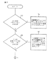
正しい記憶デバイス24が論理的ボリューム40内に見出されかつ正しく配列されているか否かの決定、および論理的識別子が特定の論理的ボリューム40に対する各記憶デバイス24で更新され、また書込まれるべきか否かの決定を開始する状況の説明に関して、以下に図2乃至図4を参照してなされる。
先ずステップ50を参照すると、特定の事象がモニタされ、上記ACM18がパワー・オンとされたか否かが判別される。この事象の発生にもとづいて、論理的ボリューム40での記憶デバイス24a〜24jの何れかが、(1)取り除かれ又は使用不能とされ、それによって該論理的ボリューム40に対して使用可能な記憶デバイス24が十分でなくなったかどうか、(2)間違った論理的ボリュームに置かれていないかどうか、(3)正しい論理的ボリューム40に置かれているが該特定の論理的ボリューム40内で間違った位置に接続されていないかどうかのチエックをすることが決定される。ステップ54では、アレイ記憶システム14の各論理的ボリュームが、図5乃至図7に示されるステップを用いてチエックされる。図5乃至図7の各ステップは後で詳細に記述される。ステップ50と同様に、ステップ58において、単一の記憶デバイスがパワー・オンとされたか否かが判別される。もしパワー・オンとされていれば、ステップ62に示されるように、図5乃至図7の各ステップがまた実行される。図2乃至図4の各ステップのつづきとして、論理的識別子が発生され又は更新されるような他の状態が検出されうる。ステップ66では、データの完全さに影響を及ぼすような、また論理的識別子を書込むことが有利であるような、いくつかのアレイ記憶システムの状況又は事象がモニタされる。好適な実施例においては、ある状況がモニタ用に、また所定の行動をとるために特定される。これらの事象又は状況として、(1)“アタッチ”コマンドの発行、および(2)初期化、構成変更、又はデータ再構成動作の存在がある。これらはユーザ入力装置、例えばターミナル60によってアレイ記憶システム14と影響し合うユーザによって開始されうる。
【0024】
発行されるアタッチコマンドに関しては、ステップ70でその発生がチエックされる。かかる場合にはステップ74で、アタッチコマンドが実行される。アタッチコマンドの実行後に、ステップ78が実行され、その結果として論理的識別子が、該アタッチコマンドと関連している特定の論理的ボリューム40に対する各記憶デバイス24に書込まれる。新しい論理的識別子の書込みにあたっては、図8および図9に示されるステップが実行される。図8および図9の各ステップについては、後で詳細に説明される。
【0025】
アタッチコマンドは記憶デバイス24をデータの受入れと記憶のために準備させる。この準備は、トラックおよびセクターの欠陥マップを読出して更新することを含んでいる。アタッチコマンドが発行されるときには、異なる記憶デバイスが論理的ボリューム40に含まれていたという事実が示される。したがって論理的識別子は、論理的ボリューム40の記憶デバイス24において更新されなければならない。更新された論理的識別子は、この異なる記憶デバイスのデバイス識別子を含むべきである。
【0026】
図2乃至図4に示されるステップ86においては、特定の論理的ボリュームに対する論理的識別子の書込みを要求するような特定のオペレーショナルな事象が発生しているかどうかの判別がなされる。該ステップ86として、初期化、自動的なデータ再構成、又は構成変更が生じているかどうかのチエックがなされることが示されている。
【0027】
初期化動作は、記憶デバイス24a〜24jが欠陥マップを更新することによって、また記憶デバイス24でのデータ記憶の割当てによって、データの読み書きに対して準備されることにおいて、アタッチコマンドの実行と類似している。しかし、初期化動作は特定の論理的ボリュームのすべての記憶デバイスに関係している。ステップ90では、論理的識別子が、ステップ94で示されるような初期化の実行に先立って書込まれる。このことは、初期化の実行中に発生するかも知れない停電の場合に重要である。すなわち、初期化の前に、論理的識別子の制御情報が、初期化が処理されるべきことを示すために更新される。もしステップ94の実行中に停電とその後のパワー回復とが生じたならば、システムは初期化が該停電時に処理されていたことを判別することができる。電力の回復に伴って、該初期化が再開され完了されうる。論理的識別子を用いてこのステータス情報をチエックすることによって、不正な欠陥および記憶割当て情報が正当なものとして、また誤まって利用されているものとして解釈されうる。初期化処理の完了に伴って、特定の論理的ボリュームに対する論理的識別子が、ステップ98に示されるように再び書込まれ又は更新される。論理的識別子内の制御情報は、このステータス情報を含むように再度更新されなければならない。
【0028】
自動的なデータ再構成と関連して上記ステップ86を参照すると、図2乃至図4に示される処理は、初期化動作と関連して既に記述したのと同じステップを含んでいるようにみえる。自動的なデータ再構成は、例えば、故障した記憶デバイス上のデータをスペアの記憶デバイス24jに再構成することを含んでいる。このことは典型的には、同じ論理的ボリューム40での正当な記憶デバイス24に存在するデータとともに、記憶デバイス24iに記憶されているパリティデータを用いることによって達成される。データ再構成に関するステータス情報は、データ再構成動作に先立って論理的識別子内に保持されるべきである。例えば停電のような、アレイ記憶システム14と関連した故障事故の際には、電力回復に伴って、論理的識別子内の制御情報が読出され、データ再構成がなされていたという趣旨の情報を提供する。このような場合には、アレイ記憶システム14は、直ちにデータ再構成動作を再開するか、又は該システムの能力に応じた動作をつづけることができる。初期化に関しては、データ再構成に伴って、該特定の論理的ボリューム40に対する論理的識別子が再び更新され、該動作が完了した事実を表わすために各記憶デバイス24に書込まれる。初期化に関しては、データ再構成の完了に伴って制御情報が修正されるので、論理的識別子が変化する。
【0029】
構成変更動作は、故障した記憶デバイスに対して置換した記憶デバイス上にデータを記憶させることに関している。好適な実施例においては、この動作はスペアの記憶デバイス24jを含むすべての記憶デバイスが該置換したデバイスにデータを書込むことに利用されることにおいて、データ再構成動作に類似している。他の2つの動作に関しては、動作の実行前と実行後に論理的識別子を更新することが有利である。
【0030】
これらの3つの動作(オペレーション)に関しての図2乃至図4の各ステップを要約すると、ステップ86ではそれらのうちの1つが呼び出されたかどうかが判別される。もしそうであれば、ステップ90で、該オペレーションが適用される論理的ボリューム40の記憶デバイス24に新しい論理的識別子が書き込まれる。新しい論理的識別子は、その特定のオペレーションと関連したステータス情報を含み、故障後におけるアレイ記憶システム14の回復の間に使用される。かかるステータス情報は論理的識別子の制御情報バイトの中に見出される。特定の論理的ボリューム40に対する各記憶デバイス24への論理的識別子の書込みのステップは、図8および図9に示されている。ステップ94は特定のオペレーションの実行に関している。ステップ98は論理的識別子が再び更新されることを示している。すなわち、論理的識別子の制御情報バイトは、該オペレーションが完了した事実を表わすために修正される。
【0031】
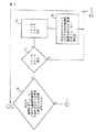
論理的識別子とデバイス識別子のチエックに関し、図5乃至図7を参照して、特定の論理的ボリューム40に正しく配置されている正しい記憶デバイス24に対するチエックにおいて、かかる識別子の使用について以下に説明される。
前述したように図2乃至図4の各ステップに応じて、正しい記憶デバイス24が特定の論理的ボリューム40内に見出されるか否かのチエックがなされるべき事象が発生し又は状態が存在したという判別がなされた。この点に関し、かかるチエックによってなされる目的は、(1)特定の論理的ボリューム40に対する位置に、正しい数の記憶デバイスがあるかどうかを判別すること、(2)すべての記憶デバイス24が特定の論理的ボリューム40の一部であるかどうかを判別すること、および(3)もしそうであれば、このような記憶デバイス24がその正しい物理的位置にあるかどうかを判別することである。図5乃至図7に示される以下のステップはこのような目的を達成するために実行される。
【0032】
先ずステップ100では、第1の記憶デバイス24aからの論理的識別子が読出され、記憶位置又はレジスタに記憶される。この記憶領域は“論理的識別子”として規定されうる。論理的ボリューム40に対する記憶デバイス24a〜24jの順序は、データが上記ACM18によって論理的ボリューム40に分配されるとき使用される順序に対応することが理解されるべきである。この順序はまた、論理的識別子と関連したデバイス識別子に対しても同じ順序又は配列でなければならない。すなわちデバイス識別子は、それらが唯一的に関連している記憶デバイス24a〜24jの順序にしたがって連続して配列される。
【0033】
ステップ104では次の記憶デバイス(例えば24b)からの論理的識別子が記憶位置又はレジスタに読出され、“次の論理的識別子”として規定されうる。ステップ108では、上記“論理的識別子”および“次の論理的識別子”に記憶された識別子情報が同じであるかどうかの判別がなされる。もし同じでなければ、記憶デバイス24aと24bは同じ論理的ボリューム40に所属していない。このような場合には、ステップ112で、これらの2つの記憶デバイスが同じ論理的ボリュームに属していないことを示すメッセージ又は応答ステータスが発生される。
【0034】
もしこれらの2つの記憶領域が同じ論理的識別子を有していれば、ステップ116で、該論理的ボリューム40に他の記憶デバイス24があるかどうか判別される。もしそうであれば、ステップ104が再度実行され、“次の論理的識別子”に記憶されるこの新しい値が、“論理的識別子”の記憶位置における論理的識別子と同一であるかどうかの判別がなされる。もしそうであれば、ステップ116で、その論理的識別子が“論理的識別子”として特定される記憶位置又はレジスタにおいて見出される論理的識別子と比較されなかったような他の記憶デバイス24があるかどうかの判別が再度なされる。上述したことから理解されるように、上記処理にはステップ104,108,および116を通る連続的なループを含んでおり、各論理的識別子が論理的ボリューム40での次の未読出の記憶デバイス24から繰返し読出され、該論理的識別子がすべて同じであるかどうかの判別がなされる。
【0035】
上述のループに対して2つの出口がある。ステップ108では、上記“論理的識別子”と“次の論理的識別子”の内容が同じでないという比較結果が示される。このような場合には、第1の記憶デバイス24aの論理識別子と最も最近に読出された論理的識別子とが同じでないという結論が導かれる。ステップ108の判定がノウであればステップ112に進み、論理的ボリューム40の一部として物理的に接続される記憶デバイスがこの特定の論理的ボリュームに属していないことを示すメッセージ又は応答ステータスが発生される。ステップ116では、論理的ボリューム40に対する記憶デバイス24から読出されるべき未読出の論理的識別子がなければ、上記ループが終結する。この場合には、これらのデバイスに対するすべての論理的識別子は同一である。更に、論理的識別子の読出の間、特定の論理的ボリューム40に対するデバイスコントローラ20へのすべてのポート又は接続もまた本質的にチエックされるので、記憶デバイス24の数が正しいという決定もなされる。すなわちもし記憶デバイスが欠如しているならば、このことが、その位置又は接続部にあるべき記憶デバイスの論理的識別子の読出しがなされたときに決定される。一旦論理的識別子が比較され、それらがすべて同じである場合には、ステップ116の判別がノウとなり、その結果記憶デバイス24が論理的ボリューム40内で正しい位置にあるかどうかの決定がなされうる。
【0036】
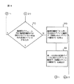
ステップ120では、第1のデバイス識別子(例えば記憶デバイス24aに対する)が論理的識別子から得られ、記憶ロケーション又はレジスタに記憶され、“期待されたデバイス識別子”として規定されうる。ステップ124では、デバイス識別子が記憶デバイス24aから読出され、記憶ロケーションに記憶され、 “実際のデバイス識別子”として規定されうる。ステップ128では、“期待されたデバイス識別子”および“実際のデバイス識別子”として記憶された内容が同じであるかどうかの比較又は判別がなされる。もしこの条件が満たされなければ、この第1の比較された記憶デバイスは、論理的識別子において指定されたような、論理的ボリューム40における正しい位置にない。この場合には、ステップ132で、この記憶デバイスが正しい位置にないことを示すメッセージ又は応答ステータスを発生する。論理的識別子におけるデバイス識別子と本質的に関係した比較をすることと関連して、論理的ボリューム内におけるその位置がある。すなわち、論理的識別子はデバイス識別子の既知の連続したアクセスにより発生されるので、第1又は次のデバイス識別子が論理的識別子の一部又はセグメントから読出されるときは、この特定の部分又はセグメントは、特定の論理的ボリューム40に対する既知のデバイス記憶位置に対応する。
【0037】
もしステップ128の判定がイエスであればステップ136に進み、他の比較がなされるべきか否か、すなわち、論理的識別子内に他のデバイス識別子があるかどうかの判別がなされる。
もしステップ136の判定がイエスであれば、ステップ120と124が再度実行される。今回は、ステップ120において、“期待されたデバイス識別子”が次の記憶デバイス(例えば記憶デバイス24b)に対応する識別子情報を有する。ステップ124では、“実際のデバイス識別子”が論理的ボリュームの第2の記憶デバイス(記憶デバイス24b)から読出されるデバイス識別子を有する。ステップ120と124とが再び実行された後、実際のデバイス識別子と期待されたデバイス識別子とが同一であるか否かの判別がステップ128でなされる。もし同一でなければ、ステップ132で、期待された情報と実際の情報との対応関係が欠如していることを示すメッセージが発生される。もしステップ128の判定がイエスであれば、ステップ136で、他の実際のデバイス識別子が、論理的識別子内に見出されるような、期待されたデバイス識別子と比較される必要があるかどうかを決定する。もし必要があれば、ステップ120,124,および128で記述したプロセスがつづけられる。
【0038】
実際のデバイス識別子と期待されたデバイス識別子との間でのすべての比較がなされた後、ステップ136で、すべての比較がなされており、論理的識別子とデバイス識別子のすべての部分で対応がとれていることの決定がなされる。ステップ140では、記憶デバイス24が正しく、かつ論理的ボリューム40内でそれらの正しい物理的位置にあることを示す出力メッセージ又は応答ステータスが提供される。
【0039】
上述した決定又は判別に関するステップに関連して、論理的識別子がデバイス識別子から発生されるので、論理的識別子内に見出されるデバイス識別子より多い実際の記憶デバイス24はありえないことが認識されるべきである。もしそのような場合があったならば、論理的識別子は特定の論理的ボリュームでのすべてのデバイス識別子から発生されるので、該論理的識別子が不正に発生されたことを意味する。論理的識別子内での記憶デバイスの数は記憶デバイスの実際の数より多くないことがステップ104,108,116で予め決定されていることもまた理解されるべきである。すなわち、実際の記憶デバイスの数は論理的識別子における記憶デバイスの数に対応することが決定されている。もし実際の記憶デバイスの数が論理的識別子内に見出される記憶デバイスの数より小さければ、ステップ112でエラー指示がなされる。
【0040】
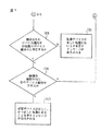
図8および図9には、論理的識別子を書込み又は更新するためのステップが示されている。前述したように、論理的識別子が更新され又は書込まれるべき事象が発生し又は条件が存在するという決定がなされた。一旦このような決定がなされると、ステップ160が実行される。特に、論理的ボリューム40における各記憶デバイス24a〜24jからのデバイス識別子について、所定の順序にしたがった反復した読出しがある。このデバイス識別子の連続的な読出しの結果、記憶デバイス24に関する位置情報が得られる。すなわち、論理的識別子を発生するとき、デバイス識別子が既知の所定の順序において論理的ボリュームに対して得られる。したがって論理的識別子が、該識別子の次のセグメント又は部分をデバイス識別子と比較するためにアクセスされるとき、どの記憶デバイス位置がそのセグメントにあてはまるかが知られる。更にステップ164では、所定の制御情報が読出され又は得られる。この情報を読出した後、ステップ168では、論理的識別子が、該論理的識別子の一部である制御バイトに含まれる制御情報とともに、論理的ボリューム40内のデバイス識別子を用いて発生される。前述したように、該制御情報バイトは、アレイ記憶システム14が故障した場合の復旧を援助するために用いられるステータス情報をアレイ記憶システム14に提供する。最後に、ステップ172では、論理的識別子が論理的ボリューム40の各記憶デバイス24a〜24jに書込まれる。論理的識別子は、各記憶デバイス24a〜24j上の指定された記憶位置に書込まれる。
【0041】
上述した本発明の説明は、図示された実施例にもとづいてなされたが、かかる実施例によって本発明が限定されるものではなく、本発明の範囲を逸脱しない範囲で、他の変形例をも含むように解釈されるべきである。
【0042】
【発明の効果】
本発明によれば、記憶アレイ内における各記憶デバイスが、該アレイ内で正しい物理的ロケーションに置かれているか否かを、確実に判別決定することができる。
【図面の簡単な説明】
【図1】本発明に用いられる基本的ハードウエア素子を示すブロック図である。
【図2】論理的識別子およびデバイス識別子の読出し、又は論理的識別子の書込みの開始に関するステップをフローチャートで示す図である。
【図3】論理的識別子およびデバイス識別子の読出し、又は論理的識別子の書込みの開始に関するステップをフローチャートで示す図である。
【図4】論理的識別子およびデバイス識別子の読出し、又は論理的識別子の書込みの開始に関するステップをフローチャートで示す図である。
【図5】論理的識別子およびデバイス識別子のチエック又は読出しに関するステップをフローチャートで示す図である。
【図6】論理的識別子およびデバイス識別子のチエック又は読出しに関するステップをフローチャートで示す図である。
【図7】論理的識別子およびデバイス識別子のチエック又は読出しに関するステップをフローチャートで示す図である。
【図8】論理的識別子の更新又は書込みに関するステップをフローチャートで示す図である。
【図9】論理的識別子の更新又は書込みに関するステップをフローチャートで示す図である。
【符号の説明】
10…ホストシステム
14…アレイ記憶システム
18…アレイコントロールモジュール
20a〜20j…デバイスコントローラ
24a〜24j…記憶デバイス
28…アレイコントロールユニット
32…プロセッサ
36…ステータス記憶ユニット
40…論理的ボリューム[0001]
[Industrial application fields]
The present invention relates to an array storage system, and more particularly to an array control module for determining whether or not each storage device is a correct member of the logical volume in a storage device array including a plurality of storage devices constituting the logical volume. And an array storage system.
In the following description, the storage device is also referred to as a storage device.
[0002]
[Prior art]
Storage systems as large-scale peripheral devices are advantageous for applying software to many businesses and technologies. In one form of such a system, storage is achieved by distributing the data to be stored over a number of independent storage devices that cooperate to define a storage device array. Such individual storage devices may include magnetic and optical disk drives, among other devices. Such a storage system has a large storage capacity. Together with the host system, these storage systems contribute to high data transmission rates. Data reliability is also achieved by using a storage array.
[0003]
Large storage capacity, for example 5.25 This is accomplished by using a number of relatively inexpensive storage devices, such as an inch magnetic disk drive. A high data transmission rate means that each storage device has one or more logical Target This is accomplished by creating a system that is grouped into a volume or group. logic Target A volume appears as a single large storage unit in the host system, even though it is composed of a number of physically independent storage devices. The storage device array typically has one logical Target Hardware and software are included to allow all storage devices in the volume to be associated simultaneously in data transmission. That is, each storage device has the logic Target Reading and writing to the volume is the logic Target It has a unique data connection as accomplished by reading and writing to each storage device in the volume. This allows large amounts of data to be quickly read from or written to the storage array. High data reliability is one or more special storage that can be used to replace hardware elements and software processing for redundant storage data, such as the use of parity information, for failed storage devices. This can be achieved by using with the device. Data on the failed device is reconstructed using the parity information and transferred to the replaced storage device until the failed device is replaced.
[0004]
The requirement that arises in connection with a storage array is that the correct storage order or arrangement in each logical volume must be known and maintained. The storage array is used to convert storage devices in a conversion between a single stream of data that can be translated by the host system and multiple parallel data streams from or to the logical volume. Use this order or sequence. This ordering of storage devices translates the data replayed from the storage device array into a single stream of information acceptable to the host system via parallel data transfer from the storage devices in the logical volume. Allow that.
[0005]
Since replacement of individual storage devices may be required, there are a number of system maintenance situations that can occur and must be compensated. For example, a storage device that is part of one logical volume may be accidentally placed in another logical volume, in which case data in the one logical volume cannot be read. As another example, a storage device within one logical volume may be tampered with, so that the data supplied by the storage device is not accepted via the correct data connection and can therefore be correctly converted. Absent. More specifically, it is known that consecutively transferred data bytes are stored on another disk. For example, for a fixed size data block,
[0006]
[Problems to be solved by the invention]
Such a problem arises due to the lack of a mechanism for automatically determining whether each storage device in the storage device array is in the correct location.
Based on such technical background, the present invention provides a processing procedure in which it can be confirmed that the above-mentioned array storage devices are logically grouped and are correctly aligned in each logical volume. It is a thing.
[0007]
[Means for Solving the Problems]
In order to solve such a problem, the present invention provides an array storage system including an array control module for confirming that each storage device is in a correct physical position in the storage device array. That is, a determination is made as to whether each storage device is installed at the correct physical location relative to the logical volume to which it belongs. Although the present invention has applicability to disk drives, it can also be associated with other storage devices.
[0008]
That is, the present invention provides a plurality of storage devices each storing different device identifiers,
Double An array control module for instructing reading or writing of storage information to a number of storage devices,
Double A number of storage devices and the array control module are removably connected,
A Ray control module Double Manage some or all of the storage devices as one logical volume, and Theory Storage information is distributed and stored in a plurality of storage devices constituting a physical volume, or Theory An array storage system that reads and combines storage information distributed and stored in a plurality of storage devices that constitute a physical volume,
Double Number of storage devices Theory Reason Target Device identifiers stored in multiple storage devices that make up the volume , Theory Reason Target Having a logical identifier associated with the positional relationship of each storage device constituting the volume,
Theory The device identifier and that each storage device that constitutes the logical volume includes a device that is not a storage device that constitutes the logical volume. , Theory Rational identifier Device identifier obtained from By comparing with Decision Means,
Decision The fixed means is in one logical volume Theory Reason Target If you decide that the volume contains storage devices that should not be configured That A reporting means for reporting events;
An array storage system comprising:
For each logical volume of the storage device, a logical identifier is generated and stored in each storage device. To do this, the present invention uses a device identifier that is uniquely and permanently associated with each storage device. Device identifier Is It can be read from a storage device (storage device). In a preferred embodiment, De The device identifier is stored at a known location Record This is the serial number of the storage device. For a given logical volume, Theory The physical identifier is composed of individual device identifiers for the volume. That is, the logical identifier for each storage device in a certain logical volume is the same, and includes all device identifier combinations for that logical volume. Logical identifiers also contain control information or bytes that provide information about the status of system operations. As an example, when the data is reconfigured in the replacement storage device, Theory The control byte of the physical identifier includes information indicating that the data is being reconstructed. The result is a waste of power, and then the power contains control bytes Theory Once recovered by reading the logical identifier, the system can determine its state prior to wasting power and use that information to restore correct operation.
[0009]
Regarding the check of the logical identifier and device identifier for a certain logical volume, for example, when a predetermined event or condition occurs after power recovery, the logical identifiers of all storage devices for the logical volume are read. If all logical identifiers correspond to each other and the correct number of logical identifiers have been read, a determination is made that the logical volume has the correct storage. In order to check whether such a storage device is correctly arranged in the logical volume, for each storage device a comparison between its own device identifier and the corresponding part or segment of the logical identifier Is made. If there is a correspondence between the device identifier and the information detected in the predetermined part of the logical identifier for each storage device, each device identifier is in the correct physical location in the logical volume. It is decided. On the other hand, if the correspondence is not established, a message or an error instruction is generated to inform the user of the lack of the correspondence.
[0010]
In addition to checking for the correct logical identifier and device identifier, the present invention also provides each volume That is, a group of storage devices Logical identification for Child Generate and update. Such updating or writing of the logical identifier occurs under some predetermined condition or event. For example, to reconstruct data for a replacement storage device on a particular logical volume, to maintain the state of the storage system against recovery from power wastage, A logical identifier is generated by reading each device identifier including the device identifier of the replaced storage device. In addition, the control byte of the logical identifier contains information about the reconfiguration of data to the replacement storage device. After the updated logical identifier is generated, each storage device is written to that particular logical volume. It should also be understood that other events or conditions can begin to write or update logical identifiers including system operations or commands where it is important to maintain continuity of the state.
[0011]
[Action]
Based on the above summary, a number of salient features according to the present invention can be readily recognized. A check to determine if the correct storage devices, such as disk drives and their attached disks, are in the correct position after a given condition or event has occurred, such as when power is restored. Is made. If the correct storage device is not in the correct physical location for a particular logical volume, a message is generated indicating that a failure has occurred. In addition, a new logical identifier for a logical volume can be updated or written so that the correct logical identifier is updated in response to the occurrence of an event or condition, such as a storage replacement. Is stored in each storage device. Each logical identifier includes a combination of a storage device identifier and control bits that provide information regarding the operation of the entire system. If power is wasted and then restored, a logical identifier check for a particular logical volume can be made in determining the state of the system when power is wasted. In this way, the tolerances for failures associated with the storage device array are further increased.
[0012]
Other advantages of the present invention will become apparent from the following description made with reference to the accompanying drawings.
[0013]
【Example】
FIG. 1 shows a system block diagram for carrying out the present invention. The system includes a
[0014]
FIG. 1 also shows that the
[0015]
The array control module (ACM) 18 has a function of converting data to and from the data format used by the
[0016]
As an example of the operation of the
[0017]
Also shown in FIG. 1 is a single
[0018]
In other embodiments, a second
[0019]
It should also be noted that the structure of the data for the storage device 24 can vary substantially. In one embodiment, consecutive bytes in a fixed size data block from the
[0020]
In using the
[0021]
In order to determine whether or not all storage devices are in the correct location within the logical volume, the present invention utilizes pre-stored and subsequently determined information. The prestored information includes a “device identifier” (device identifier) for each of the storage devices 24. The device identifier is a unique and permanent identification code for each of the storage devices 24. Preferably, the device identifier is a serial number for a particular storage device. The determined information includes a “logical identifier” for each
[0022]
In addition to checking the correct storage device 24 in the
[0023]
Determining whether the correct storage device 24 is found in the
Referring first to step 50, a specific event is monitored to determine if the
[0024]
As for the issued attach command, its generation is checked in step 70. In such a case, in
[0025]
The attach command causes the storage device 24 to prepare for data acceptance and storage. This preparation includes reading and updating track and sector defect maps. When the attach command is issued, the fact that a different storage device was included in the
[0026]
In
[0027]
The initialization operation is similar to the execution of an attach command in that the storage devices 24a-24j are prepared for reading and writing data by updating the defect map and by allocating data storage at the storage device 24. ing. However, the initialization operation is related to all storage devices of a specific logical volume. In
[0028]
Referring to step 86 above in connection with automatic data reconstruction, the process shown in FIGS. 2-4 appears to include the same steps already described in connection with the initialization operation. Automatic data reconfiguration includes, for example, reconfiguring data on a failed storage device to a
[0029]
The reconfiguration operation relates to storing data on a storage device that replaces the failed storage device. In the preferred embodiment, this operation is similar to the data reconstruction operation in that all storage devices, including
[0030]
Summarizing each of the steps of FIGS. 2-4 for these three operations, step 86 determines whether one of them has been invoked. If so, at
[0031]
Regarding the checking of logical identifiers and device identifiers, with reference to FIGS. 5-7, the use of such identifiers in a check for the correct storage device 24 correctly placed in a particular
As described above, according to each step of FIGS. 2 to 4, an event has occurred or a condition has to be checked whether or not the correct storage device 24 is found in a specific
[0032]
First, at
[0033]
In
[0034]
If these two storage areas have the same logical identifier, it is determined at
[0035]
There are two exits for the loop described above. In
[0036]
In
[0037]
If the determination in
If the determination in
[0038]
After all comparisons between actual and expected device identifiers have been made, at
[0039]
In connection with the determination or discrimination steps described above, it should be appreciated that there can be no more actual storage devices 24 than the device identifiers found in the logical identifier, since the logical identifier is generated from the device identifier. . If this is the case, the logical identifier is generated from all device identifiers in a particular logical volume, which means that the logical identifier has been generated illegally. It should also be understood that it has been predetermined in
[0040]
8 and 9 show the steps for writing or updating the logical identifier. As previously described, a determination has been made that an event has occurred or a condition exists for which the logical identifier is to be updated or written. Once such a determination is made, step 160 is executed. In particular, device identifiers from each storage device 24a-24j in the
[0041]
The above description of the present invention has been made based on the illustrated embodiment. However, the present invention is not limited to the illustrated embodiment, and other modifications may be made without departing from the scope of the present invention. Should be construed to include.
[0042]
【The invention's effect】
According to the present invention, it is possible to reliably determine whether or not each storage device in a storage array is placed at a correct physical location in the array.
[Brief description of the drawings]
FIG. 1 is a block diagram showing basic hardware elements used in the present invention.
FIG. 2 is a flowchart illustrating steps relating to the start of reading logical identifiers and device identifiers, or writing logical identifiers.
FIG. 3 is a flowchart illustrating steps relating to the start of reading logical identifiers and device identifiers, or starting writing logical identifiers.
FIG. 4 is a flowchart illustrating steps relating to the start of reading logical identifiers and device identifiers, or writing logical identifiers.
FIG. 5 is a flowchart showing the steps involved in checking or reading logical identifiers and device identifiers.
FIG. 6 is a flowchart showing the steps involved in checking or reading logical identifiers and device identifiers.
FIG. 7 is a flowchart showing the steps involved in checking or reading logical identifiers and device identifiers.
FIG. 8 is a flowchart illustrating steps related to updating or writing a logical identifier.
FIG. 9 is a flowchart illustrating steps related to updating or writing a logical identifier.
[Explanation of symbols]
10 ... Host system
14 ... Array storage system
18 ... Array control module
20a-20j ... Device controller
24a-24j ... Storage device
28 ... Array control unit
32. Processor
36 ... Status storage unit
40: Logical volume
Claims (1)
前記複数の記憶デバイスに対して、記憶情報の読み出し又は書込みを指示するアレイコントロールモジュールと、を有し、
前記複数の記憶デバイスとアレイコントロールモジュールとは、取り外し可能に接続され、
前記アレイコントロールモジュールは、前記複数の記憶デバイスの一部または全部を一つの論理的ボリュームとして管理し、更に、前記論理的ボリュームを構成する複数の記憶デバイスに記憶情報を分散して格納し又は前記論理的ボリュームを構成する複数の記憶デバイスに分散して格納されている記憶情報を読み出して結合するアレイ記憶システムであって、
前記複数の記憶デバイスは、前記論理的ボリュームを構成する複数の記憶デバイスに格納されているデバイス識別子と、前記論理的ボリュームを構成する各記憶デバイスの位置関係とを関連付けた論理的識別子を有し、
前記論理的ボリュームを構成すべき各記憶デバイスの中に、その論理的ボリュームを構成する記憶デバイスではないものが含まれていることを、前記デバイス識別子と、前記論理的識別子から得られるデバイス識別子とを比較することにより決定する決定手段と、
前記決定手段が、一つの論理的ボリュームの中に前記論理的ボリュームを構成すべきでない記憶デバイスが含まれていることを決定した場合にその事象を通報する通報手段と、
を備えてなるアレイ記憶システム。A plurality of storage devices each storing a different device identifier;
Wherein for a plurality of storage devices, comprising an array control module for instructing the reading or writing of stored information, and
The plurality of storage devices and the array control module are detachably connected,
Said array control module, the plurality of part or all of the storage device managed as a single logical volume, further, stored in a distributed storage information in a plurality of storage devices constituting the logical volume or the An array storage system that reads and combines storage information distributed and stored in a plurality of storage devices constituting a logical volume,
Wherein the plurality of storage devices, and a device identifier stored in the plurality of storage devices constituting the logical volume, the logical identifier associated with the position relation of the respective storage devices constituting the logical volume Have
Within each storage device should constitute the logical volume that it contains those not storage devices constituting the logical volume, and the device identifier, a device identifier obtained from the logical identifiers Determining means for determining by comparing
And notification means for said determining means notifies the event if it is decided that contains one of the should not constitute a logical volume storage device in the logical volume,
An array storage system comprising:
Applications Claiming Priority (2)
| Application Number | Priority Date | Filing Date | Title |
|---|---|---|---|
| US07/794,114 US5369758A (en) | 1991-11-15 | 1991-11-15 | Checking for proper locations of storage devices in a storage array |
| US794114 | 1991-11-15 |
Related Parent Applications (1)
| Application Number | Title | Priority Date | Filing Date |
|---|---|---|---|
| JP29440392A Division JP3221747B2 (en) | 1991-11-15 | 1992-11-02 | Storage device array |
Publications (2)
| Publication Number | Publication Date |
|---|---|
| JP2001356941A JP2001356941A (en) | 2001-12-26 |
| JP3631442B2 true JP3631442B2 (en) | 2005-03-23 |
Family
ID=25161756
Family Applications (3)
| Application Number | Title | Priority Date | Filing Date |
|---|---|---|---|
| JP29440392A Expired - Fee Related JP3221747B2 (en) | 1991-11-15 | 1992-11-02 | Storage device array |
| JP33278198A Expired - Fee Related JP3243223B2 (en) | 1991-11-15 | 1998-11-24 | Storage device array |
| JP2001134690A Expired - Lifetime JP3631442B2 (en) | 1991-11-15 | 2001-05-01 | Array storage system |
Family Applications Before (2)
| Application Number | Title | Priority Date | Filing Date |
|---|---|---|---|
| JP29440392A Expired - Fee Related JP3221747B2 (en) | 1991-11-15 | 1992-11-02 | Storage device array |
| JP33278198A Expired - Fee Related JP3243223B2 (en) | 1991-11-15 | 1998-11-24 | Storage device array |
Country Status (4)
| Country | Link |
|---|---|
| US (3) | US5369758A (en) |
| EP (1) | EP0541996B1 (en) |
| JP (3) | JP3221747B2 (en) |
| DE (1) | DE69224589T2 (en) |
Families Citing this family (73)
| Publication number | Priority date | Publication date | Assignee | Title |
|---|---|---|---|---|
| US5522031A (en) * | 1993-06-29 | 1996-05-28 | Digital Equipment Corporation | Method and apparatus for the on-line restoration of a disk in a RAID-4 or RAID-5 array with concurrent access by applications |
| US5752257A (en) * | 1994-07-29 | 1998-05-12 | Nomai Sa | Redundant array of removable cartridge disk drives |
| US5548712A (en) * | 1995-01-19 | 1996-08-20 | Hewlett-Packard Company | Data storage system and method for managing asynchronous attachment and detachment of storage disks |
| JP3686457B2 (en) * | 1995-08-31 | 2005-08-24 | 株式会社日立製作所 | Disk array subsystem |
| US5632027A (en) * | 1995-09-14 | 1997-05-20 | International Business Machines Corporation | Method and system for mass storage device configuration management |
| JPH10105345A (en) * | 1996-09-27 | 1998-04-24 | Fujitsu Ltd | Array disk device |
| US6438663B1 (en) * | 1996-12-11 | 2002-08-20 | Steeleye Technology, Inc. | System and method for identifying shared virtual memory in a computer cluster |
| US6092169A (en) * | 1997-04-02 | 2000-07-18 | Compaq Computer Corporation | Apparatus and method for storage subsystem drive movement and volume addition |
| US6041329A (en) * | 1997-05-29 | 2000-03-21 | International Business Machines Corporation | Automated message processing system configured to automatically manage introduction of removable data storage media into media library |
| US5999982A (en) * | 1997-05-29 | 1999-12-07 | International Business Machines Corporation | Automated message processing system having a plurality of expert local facilities responsive to messages routed thereto to perform predetermined actions |
| US5911148A (en) * | 1997-05-29 | 1999-06-08 | International Business Machines Corporation | Automated message processing system configured for automated tape device management |
| AU8270598A (en) * | 1997-06-27 | 1999-01-19 | Unisys Corporation | Method of operating a raid disk array in a hardware-address-independent manner, and disk storage system which performs such method |
| US6178520B1 (en) * | 1997-07-31 | 2001-01-23 | Lsi Logic Corporation | Software recognition of drive removal or insertion in a storage system |
| US6016553A (en) | 1997-09-05 | 2000-01-18 | Wild File, Inc. | Method, software and apparatus for saving, using and recovering data |
| AU3075899A (en) * | 1998-03-10 | 1999-09-27 | Quad Research | High speed fault tolerant mass storage network information server |
| US6732293B1 (en) * | 1998-03-16 | 2004-05-04 | Symantec Corporation | Method, software and apparatus for recovering and recycling data in conjunction with an operating system |
| US6363487B1 (en) | 1998-03-16 | 2002-03-26 | Roxio, Inc. | Apparatus and method of creating a firewall data protection |
| US6463550B1 (en) | 1998-06-04 | 2002-10-08 | Compaq Information Technologies Group, L.P. | Computer system implementing fault detection and isolation using unique identification codes stored in non-volatile memory |
| US6496945B2 (en) * | 1998-06-04 | 2002-12-17 | Compaq Information Technologies Group, L.P. | Computer system implementing fault detection and isolation using unique identification codes stored in non-volatile memory |
| EP0969371A1 (en) * | 1998-06-30 | 2000-01-05 | Sun Microsystems, Inc. | Verifying configuration of storage devices based upon device indentifiers |
| US7055055B1 (en) | 1999-04-23 | 2006-05-30 | Symantec Corporation | Write cache flushing method for reducing data corruption |
| US6915475B1 (en) * | 1999-06-29 | 2005-07-05 | Emc Corporation | Data integrity management for data storage systems |
| US7051055B1 (en) | 1999-07-09 | 2006-05-23 | Symantec Corporation | Optimized disk storage defragmentation with swapping capabilities |
| WO2001004801A1 (en) * | 1999-07-09 | 2001-01-18 | Wild File, Inc. | Optimized disk storage defragmentation with swapping capabilities |
| US6658585B1 (en) | 1999-10-07 | 2003-12-02 | Andrew E. Levi | Method and system for simple network management protocol status tracking |
| US6833787B1 (en) | 1999-10-07 | 2004-12-21 | Asap Software Express, Inc. | Method and system for device tracking |
| US6477667B1 (en) | 1999-10-07 | 2002-11-05 | Critical Devices, Inc. | Method and system for remote device monitoring |
| US6636983B1 (en) | 1999-10-07 | 2003-10-21 | Andrew E. Levi | Method and system for uniform resource locator status tracking |
| US6658586B1 (en) | 1999-10-07 | 2003-12-02 | Andrew E. Levi | Method and system for device status tracking |
| AU1237701A (en) * | 1999-10-29 | 2001-05-14 | Wild File, Inc. | Apparatus and method of creating a firewall data protection |
| US6704730B2 (en) | 2000-02-18 | 2004-03-09 | Avamar Technologies, Inc. | Hash file system and method for use in a commonality factoring system |
| US7194504B2 (en) * | 2000-02-18 | 2007-03-20 | Avamar Technologies, Inc. | System and method for representing and maintaining redundant data sets utilizing DNA transmission and transcription techniques |
| US6826711B2 (en) | 2000-02-18 | 2004-11-30 | Avamar Technologies, Inc. | System and method for data protection with multidimensional parity |
| US7062648B2 (en) * | 2000-02-18 | 2006-06-13 | Avamar Technologies, Inc. | System and method for redundant array network storage |
| US7509420B2 (en) | 2000-02-18 | 2009-03-24 | Emc Corporation | System and method for intelligent, globally distributed network storage |
| FR2807531B1 (en) * | 2000-04-06 | 2003-09-19 | Renault | METHOD FOR CHECKING THE CONSISTENCY OF A SET OF INTEGRATED ELECTRONIC SYSTEMS |
| JP4633886B2 (en) * | 2000-05-25 | 2011-02-16 | 株式会社日立製作所 | Disk array device |
| US7225191B1 (en) | 2000-06-27 | 2007-05-29 | Emc Corporation | Method and apparatus for verifying storage access requests in a computer storage system with multiple storage elements |
| US6813686B1 (en) * | 2000-06-27 | 2004-11-02 | Emc Corporation | Method and apparatus for identifying logical volumes in multiple element computer storage domains |
| US7065610B1 (en) | 2000-06-27 | 2006-06-20 | Emc Corporation | Method and apparatus for maintaining inventory of logical volumes stored on storage elements |
| US6978324B1 (en) * | 2000-06-27 | 2005-12-20 | Emc Corporation | Method and apparatus for controlling read and write accesses to a logical entity |
| US6760828B1 (en) | 2000-06-27 | 2004-07-06 | Emc Corporation | Method and apparatus for using logical volume identifiers for tracking or identifying logical volume stored in the storage system |
| US6842784B1 (en) | 2000-06-27 | 2005-01-11 | Emc Corporation | Use of global logical volume identifiers to access logical volumes stored among a plurality of storage elements in a computer storage system |
| US6708265B1 (en) | 2000-06-27 | 2004-03-16 | Emc Corporation | Method and apparatus for moving accesses to logical entities from one storage element to another storage element in a computer storage system |
| GB2368412A (en) * | 2000-10-26 | 2002-05-01 | Hewlett Packard Co | Managing disk drive replacements |
| US6810398B2 (en) | 2000-11-06 | 2004-10-26 | Avamar Technologies, Inc. | System and method for unorchestrated determination of data sequences using sticky byte factoring to determine breakpoints in digital sequences |
| US6732231B1 (en) * | 2001-02-28 | 2004-05-04 | Emc Corporation | System and method for management of mirrored storage devices storing device serial numbers |
| US6496914B1 (en) * | 2001-03-22 | 2002-12-17 | Emc Corporation | Method and system for administering storage devices on a network |
| US7200609B2 (en) * | 2001-07-19 | 2007-04-03 | Emc Corporation | Attribute based resource allocation |
| US7478758B2 (en) * | 2003-07-15 | 2009-01-20 | Lsi Corporation | Method and apparatus for automatically tracking and communicating data storage device information using RF tags: operating condition, configuration and location |
| US7409587B2 (en) * | 2004-08-24 | 2008-08-05 | Symantec Operating Corporation | Recovering from storage transaction failures using checkpoints |
| US7991748B2 (en) * | 2003-09-23 | 2011-08-02 | Symantec Corporation | Virtual data store creation and use |
| US7287133B2 (en) * | 2004-08-24 | 2007-10-23 | Symantec Operating Corporation | Systems and methods for providing a modification history for a location within a data store |
| US7904428B2 (en) * | 2003-09-23 | 2011-03-08 | Symantec Corporation | Methods and apparatus for recording write requests directed to a data store |
| US7239581B2 (en) * | 2004-08-24 | 2007-07-03 | Symantec Operating Corporation | Systems and methods for synchronizing the internal clocks of a plurality of processor modules |
| US7631120B2 (en) * | 2004-08-24 | 2009-12-08 | Symantec Operating Corporation | Methods and apparatus for optimally selecting a storage buffer for the storage of data |
| US7296008B2 (en) * | 2004-08-24 | 2007-11-13 | Symantec Operating Corporation | Generation and use of a time map for accessing a prior image of a storage device |
| US7577806B2 (en) * | 2003-09-23 | 2009-08-18 | Symantec Operating Corporation | Systems and methods for time dependent data storage and recovery |
| US7577807B2 (en) * | 2003-09-23 | 2009-08-18 | Symantec Operating Corporation | Methods and devices for restoring a portion of a data store |
| US7730222B2 (en) * | 2004-08-24 | 2010-06-01 | Symantec Operating System | Processing storage-related I/O requests using binary tree data structures |
| US7725760B2 (en) * | 2003-09-23 | 2010-05-25 | Symantec Operating Corporation | Data storage system |
| US7827362B2 (en) | 2004-08-24 | 2010-11-02 | Symantec Corporation | Systems, apparatus, and methods for processing I/O requests |
| US7949665B1 (en) | 2004-11-19 | 2011-05-24 | Symantec Corporation | Rapidly traversing disc volumes during file content examination |
| US7454686B2 (en) * | 2004-11-23 | 2008-11-18 | International Business Machines Corporation | Apparatus and method to check data integrity when handling data |
| CN103927238B (en) * | 2005-10-14 | 2017-04-12 | 塞门铁克操作公司 | Technique For Timeline Compression In Data Store |
| KR101381551B1 (en) | 2006-05-05 | 2014-04-11 | 하이버 인크 | Group based complete and incremental computer file backup system, process and apparatus |
| US8131919B1 (en) * | 2007-12-21 | 2012-03-06 | Emc Corporation | Techniques for controlling storage device use by performing a storage device location assessment operation based on a current storage device identifier |
| CN102457373B (en) * | 2010-10-19 | 2016-09-07 | 鸿富锦精密工业(深圳)有限公司 | Handheld device bi-directional verification system and method |
| JP5817498B2 (en) * | 2011-12-15 | 2015-11-18 | 富士通株式会社 | Management system, management apparatus, and electronic device management method |
| US8966211B1 (en) * | 2011-12-19 | 2015-02-24 | Emc Corporation | Techniques for dynamic binding of device identifiers to data storage devices |
| EP2629164B1 (en) * | 2012-02-14 | 2014-12-17 | Siemens Aktiengesellschaft | Method and configuration component for allocating a station name to components of an industrial automation assembly |
| US10108479B2 (en) * | 2015-10-07 | 2018-10-23 | Unisys Corporation | Device expected state monitoring and remediation |
| US11338831B2 (en) | 2018-11-21 | 2022-05-24 | Jac Operations, Inc. | Railcar having cold formed center sill with stiffness enhancing structure |
Family Cites Families (11)
| Publication number | Priority date | Publication date | Assignee | Title |
|---|---|---|---|---|
| US3914747A (en) * | 1974-02-26 | 1975-10-21 | Periphonics Corp | Memory having non-fixed relationships between addresses and storage locations |
| US4779189A (en) * | 1985-06-28 | 1988-10-18 | International Business Machines Corporation | Peripheral subsystem initialization method and apparatus |
| US4924331A (en) * | 1985-11-20 | 1990-05-08 | Seagate Technology, Inc. | Method for mapping around defective sectors in a disc drive |
| US5051887A (en) * | 1987-08-25 | 1991-09-24 | International Business Machines Corporation | Maintaining duplex-paired storage devices during gap processing using of a dual copy function |
| JPH01108634A (en) * | 1987-10-21 | 1989-04-25 | Nec Corp | System for preventing erroneous usage of external recording medium |
| US4935825A (en) * | 1988-12-16 | 1990-06-19 | Emulex Corporation | Cylinder defect management system for data storage system |
| US5101492A (en) * | 1989-11-03 | 1992-03-31 | Compaq Computer Corporation | Data redundancy and recovery protection |
| DE69032614T2 (en) * | 1989-11-03 | 1999-04-15 | Compaq Computer Corp., Houston, Tex. 77070 | Data distribution method in a disk array |
| US5233618A (en) * | 1990-03-02 | 1993-08-03 | Micro Technology, Inc. | Data correcting applicable to redundant arrays of independent disks |
| US5325497A (en) * | 1990-03-29 | 1994-06-28 | Micro Technology, Inc. | Method and apparatus for assigning signatures to identify members of a set of mass of storage devices |
| US5208813A (en) * | 1990-10-23 | 1993-05-04 | Array Technology Corporation | On-line reconstruction of a failed redundant array system |
-
1991
- 1991-11-15 US US07/794,114 patent/US5369758A/en not_active Expired - Lifetime
-
1992
- 1992-10-20 DE DE69224589T patent/DE69224589T2/en not_active Expired - Fee Related
- 1992-10-20 EP EP92117910A patent/EP0541996B1/en not_active Expired - Lifetime
- 1992-11-02 JP JP29440392A patent/JP3221747B2/en not_active Expired - Fee Related
-
1994
- 1994-10-19 US US08/325,989 patent/US5598528A/en not_active Expired - Lifetime
-
1996
- 1996-05-13 US US08/645,124 patent/US5751936A/en not_active Expired - Fee Related
-
1998
- 1998-11-24 JP JP33278198A patent/JP3243223B2/en not_active Expired - Fee Related
-
2001
- 2001-05-01 JP JP2001134690A patent/JP3631442B2/en not_active Expired - Lifetime
Also Published As
| Publication number | Publication date |
|---|---|
| EP0541996A2 (en) | 1993-05-19 |
| JPH11242568A (en) | 1999-09-07 |
| DE69224589T2 (en) | 1998-06-25 |
| EP0541996A3 (en) | 1994-01-05 |
| EP0541996B1 (en) | 1998-03-04 |
| US5369758A (en) | 1994-11-29 |
| JP2001356941A (en) | 2001-12-26 |
| JP3243223B2 (en) | 2002-01-07 |
| US5751936A (en) | 1998-05-12 |
| DE69224589D1 (en) | 1998-04-09 |
| US5598528A (en) | 1997-01-28 |
| JP3221747B2 (en) | 2001-10-22 |
| JPH05210464A (en) | 1993-08-20 |
Similar Documents
| Publication | Publication Date | Title |
|---|---|---|
| JP3631442B2 (en) | Array storage system | |
| US6408400B2 (en) | Disk array device | |
| JP2501752B2 (en) | Storage device of computer system and method of storing data | |
| JP3058743B2 (en) | Disk array controller | |
| JP2690436B2 (en) | Storage device array system and method of operating the same | |
| US9122410B2 (en) | Storage system comprising function for changing data storage mode using logical volume pair | |
| EP0303855B1 (en) | Identification of data storage devices | |
| TWI223146B (en) | Method and system for upgrading drive firmware in a non-disruptive manner | |
| US6535994B1 (en) | Method and apparatus for identifying and repairing mismatched data | |
| US6233696B1 (en) | Data verification and repair in redundant storage systems | |
| JPH04205519A (en) | Writing method of data under restoration | |
| JP2008071209A (en) | Storage management program, storage management device, and storage management method | |
| JPH09231016A (en) | Method and device for production of data snap shot copy in raid storage subsystem | |
| US6389511B1 (en) | On-line data verification and repair in redundant storage system | |
| US6301711B1 (en) | System and method for the network support of full motion video using a redundant array of inexpensive disks | |
| JP2001344076A (en) | Disk array device | |
| JPH07200191A (en) | Disk array device | |
| US20050033933A1 (en) | Systems and methods for modifying disk drive firmware in a raid storage system | |
| US20050246576A1 (en) | Redundant system utilizing remote disk mirroring technique, and initialization method for remote disk mirroring for in the system | |
| EP0303856B1 (en) | Method and apparatus for maintaining duplex-paired devices by means of a dual copy function | |
| JPH07261945A (en) | Disk array device and disk array sorting method | |
| JPH07306758A (en) | Disk array device and control method thereof | |
| JP3597349B2 (en) | Storage subsystem and fault recovery method thereof | |
| JP3155836B2 (en) | Disk array device | |
| JPH0962586A (en) | Information processing apparatus and data processing method in information processing apparatus |
Legal Events
| Date | Code | Title | Description |
|---|---|---|---|
| A131 | Notification of reasons for refusal |
Free format text: JAPANESE INTERMEDIATE CODE: A131 Effective date: 20040713 |
|
| A521 | Request for written amendment filed |
Free format text: JAPANESE INTERMEDIATE CODE: A523 Effective date: 20040910 |
|
| TRDD | Decision of grant or rejection written | ||
| A01 | Written decision to grant a patent or to grant a registration (utility model) |
Free format text: JAPANESE INTERMEDIATE CODE: A01 Effective date: 20041116 |
|
| A61 | First payment of annual fees (during grant procedure) |
Free format text: JAPANESE INTERMEDIATE CODE: A61 Effective date: 20041216 |
|
| R150 | Certificate of patent or registration of utility model |
Free format text: JAPANESE INTERMEDIATE CODE: R150 |
|
| FPAY | Renewal fee payment (event date is renewal date of database) |
Free format text: PAYMENT UNTIL: 20071224 Year of fee payment: 3 |
|
| FPAY | Renewal fee payment (event date is renewal date of database) |
Free format text: PAYMENT UNTIL: 20081224 Year of fee payment: 4 |
|
| FPAY | Renewal fee payment (event date is renewal date of database) |
Free format text: PAYMENT UNTIL: 20091224 Year of fee payment: 5 |
|
| FPAY | Renewal fee payment (event date is renewal date of database) |
Free format text: PAYMENT UNTIL: 20091224 Year of fee payment: 5 |
|
| FPAY | Renewal fee payment (event date is renewal date of database) |
Free format text: PAYMENT UNTIL: 20101224 Year of fee payment: 6 |
|
| FPAY | Renewal fee payment (event date is renewal date of database) |
Free format text: PAYMENT UNTIL: 20111224 Year of fee payment: 7 |
|
| FPAY | Renewal fee payment (event date is renewal date of database) |
Free format text: PAYMENT UNTIL: 20111224 Year of fee payment: 7 |
|
| FPAY | Renewal fee payment (event date is renewal date of database) |
Free format text: PAYMENT UNTIL: 20121224 Year of fee payment: 8 |
|
| EXPY | Cancellation because of completion of term |