JP3630552B2 - Automatic stripping method for long materials - Google Patents
Automatic stripping method for long materials Download PDFInfo
- Publication number
- JP3630552B2 JP3630552B2 JP9875698A JP9875698A JP3630552B2 JP 3630552 B2 JP3630552 B2 JP 3630552B2 JP 9875698 A JP9875698 A JP 9875698A JP 9875698 A JP9875698 A JP 9875698A JP 3630552 B2 JP3630552 B2 JP 3630552B2
- Authority
- JP
- Japan
- Prior art keywords
- position information
- chucking
- wrinkle
- circumferential direction
- grinding
- Prior art date
- Legal status (The legal status is an assumption and is not a legal conclusion. Google has not performed a legal analysis and makes no representation as to the accuracy of the status listed.)
- Expired - Lifetime
Links
Images


Landscapes
- Investigating Or Analyzing Materials By The Use Of Ultrasonic Waves (AREA)
- Investigating Or Analyzing Materials By The Use Of Magnetic Means (AREA)
- Constituent Portions Of Griding Lathes, Driving, Sensing And Control (AREA)
- Finish Polishing, Edge Sharpening, And Grinding By Specific Grinding Devices (AREA)
Description
【0001】
【発明の属する技術分野】
本発明は丸棒鋼、鋼管等の長尺材料の表面疵を全断面疵検査装置により検査し、選別された疵有り材料の疵位置情報をもとに自動研削する長尺材料の自動疵取り方法に関する。とりわけ本発明は、疵が長尺材料のどの位置にあっても、迅速かつ正確な自動疵取りができる長尺材料の自動疵取り方法に関する。
【0002】
【従来の技術】
この種の従来技術として、例えば特公昭52−15054号「分離型自動疵取り装置における疵位置規定方法」がある。
【0003】
この方法は、疵検査装置と研削機が分離配置されており、検査時に被処理材に光学的手段により検出できるラベルなどの基準点を設け、研削時に光学的検出器で検出し疵位置情報の基準とさせ、研削機の研削位置制御を行なうものである。
【0004】
【発明が解決しようとする課題】
前記「従来の技術」に示す例のような、丸棒鋼などの被検材に、ラベルを張り付けたり、即乾性のインクやペイントを吹き付けたりする方法は、現実には、位置の正確さ、種々の疵模様に対する精度等の点で決して十分なものではなかった。特に、探傷速度の速い(例えば100m/min以上)ラインや細径の曲がりの有る材料等における適用が困難であった。
【0005】
また、表面検査装置の直後には、水を使う超音波探傷機が有る場合が有り、このようなライン構成では、ラベルの外れ、マーキングのにじみ等が発生し、原点位置の精度や確実性を要する自動疵取り装置への適用が困難である。
【0006】
さらに、疵探傷中、搬送ロールの磨耗などで材料がねじれ走行する場合が有り、基準マークが1ケ所の場合疵の位置情報マップもねじれ不正確となり、自動研削の位置ズレを起こす。
【0007】
【課題を解決するための手段】
本発明は前記課題を解決し、迅速かつ正確な自動疵取りができる長尺材料の自動疵取りラインを提供するものであり、その要旨は特許請求の範囲に記載のとおりである。すなわち、1.丸棒鋼、鋼管等の長尺材料の表面疵を全断面疵検査装置により検査し、疵有り材料と疵無し材料を選別し、次いで疵有り材料について、前記全断面疵検査装置により得られた疵長手方向位置情報を記憶装置に記憶して、材料順にトラッキング処理をし、次いで疵有り材料が疵研削位置に到達した際、研削機と直結された周方向疵探査機を、当該疵有り材料について前記の記憶装置に記憶した疵長手方向位置情報に基いて、当該疵有り材料の長手方向疵座標位置に移動し、さらに当該疵有り材料の一端部をチャッキングして回転させ、前記周方向疵探査機によって疵周方向位置を特定し、その後、当該疵有り材料をチャッキング装置で固定し、次いでチャッキング部分に疵が有る材料と無い材料を分別し、チャッキング部分に疵が無い材料の場合はチャッキングしたまま前記の特定された疵位置情報に基いて疵を自動研削し、チャッキング部分に疵の有る材料の場合は、チャッキング部分の疵を研削する際、該材料をクランプ装置により支持した後、チャッキング装置をはずし疵からチャックを逃がして疵を自動研削することを特徴とする長尺材料の自動疵取り方法。
【0008】
2.丸棒鋼、鋼管等の長尺材料の表面疵を全断面疵検査装置により検査し、疵有り材料と疵無し材料を選別し、次いで疵有り材料について、前記全断面疵検査装置により得られた疵長手方向位置情報および第一の疵周方向位置情報を記憶装置に記憶して、材料順にトラッキング処理をし、次いで疵有り材料が疵研削位置に到達した際、研削機と直結された周方向疵探査機を、当該疵有り材料について前記の記憶装置に記憶した疵長手方向位置情報に基いて、当該疵有り材料の長手方向疵座標位置に移動し、さらに当該疵有り材料の一端部をチャッキングして回転させ、前記周方向疵探査機によって第二の疵周方向位置情報を得、該第二の疵周方向位置情報を前記の記憶装置に記憶した第一の疵周方向位置情報と照合し、一致した部分を研削位置として特定し、その後、当該疵有り材料をチャッキング装置で固定し、次いでチャッキング部分に疵が有る材料と無い材料を分別し、チャッキング部分に疵が無い材料の場合はチャッキングしたまま前記の特定された疵位置情報に基いて疵を自動研削し、チャッキング部分に疵の有る材料の場合は、チャッキング部分の疵を研削する際、該材料をクランプ装置により支持した後、チャッキング装置をはずし、疵からチャックを逃がして疵を自動研削することを特徴とする長尺材料の自動疵取り方法。
【0009】
である。
【0010】
本発明において用いる全断面疵検査装置としては、漏洩磁束探疵装置、あるいは渦流探疵装置が用いられ、センサーが回転し材料が直進する形態のものと、逆にセンサーが固定で材料が回転する形態のものが有り、両者共に適用できる。
【0011】
この全断面疵検査装置による疵の長手方向の疵位置情報、あるいは加えて疵の周方向の疵位置情報を、当該疵有り材料の研削テーブルまでの搬送と同期させて、トラッキング処理する。この全断面疵検査装置による疵位置情報は、本願請求項1に記載の発明のように、疵の長手方向の疵位置情報のみであっても後に研削機と直結された周方向疵探査機が疵周方向位置を特定できるので疵研削が可能であるが、本願請求項2に記載の発明のように、疵の周方向位置情報も記憶しておき(第一の疵周方向位置情報)、後の研削機と直結された周方向疵探査機により得られる疵周方向位置情報(第二の疵周方向位置情報)と照合して疵位置を特定する方法も実際的である。すなわち、この後者の方法によれば、例えば複数の疵が存する場合に、初めの全断面疵検査装置による疵位置情報(いわゆる疵マップ)を主に利用し、一か所の疵位置情報を照合するのみで、全疵位置を特定でき自動研削することが可能となるといった利点がある。
【0012】
周方向に細かく分割した疵位置情報も一緒に取り込んでおくと予め疵の個数分布が分かり、その情報を元に、効率的な研削機の制御の情報源として活用できるものである。
【0013】
研削機と直結された周方向疵探査機は、通常全断面疵検査装置と同等の疵検出能力を持つ探傷装置を用いることが好ましい。また、自動研削機と周方向疵探査機は直結させてあり、これにより探査機と研削機の機械的位置ズレはほとんど無くなり、探査した疵を確実に研削出来る。
【0014】
この研削機と直結された周方向疵探査機により疵を探査する際、当該疵有り材料の一端部をチャッキングして回転させる。これにより、疵の周方向位置を特定することができるものである。しかし、疵位置が材料のチャッキング部分に重なる場合があり、そのままでは自動研削が困難となる。
【0015】
そこで本発明においては、次いでチャッキング部分に疵が有る材料と無い材料を分別し、チャッキング部分に疵が無い材料の場合はチャッキングしたまま前記の特定された疵位置情報に基いて疵を自動研削し、チャッキング部分に疵の有る材料の場合は、チャッキング部分の疵を研削する際、該材料をクランプ装置により支持してチャッキング装置を逃がし疵を自動研削できるように構成したものである。
【0016】
本願請求項2に記載の本発明は、全断面疵検査装置により得られた第一の疵周方向位置情報と、研削機と直結された周方向疵探査機により得られた第二の疵周方向位置情報を照合し、該照合結果に基いて自動研削することを特徴とする。これにより、より正確な自動研削を行うことができるものである。
【0017】
例えば、全断面疵検査装置により得られた第一の疵周方向位置情報(疵マップ)において、同一円周上に2個以上の疵がある場合、研削機と直結された周方向疵探査機により得られた第二の疵周方向位置情報における各々の疵が、第一の疵周方向位置情報(疵マップ)のどちらに相当するか判別する方法が必要であるが、両者の位置情報(疵マップ)において円周方向の基準点が明確でないので、それぞれの疵の相対位置情報で照合する必要があり、その判別が適切でないと間違った研削を行うことになる。
【0018】
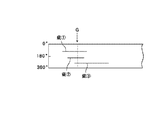
また、例えば、図1に示すように3個の疵がある場合でGの位置を探査する時、図2に示すように、疵▲3▼のレベルよりも材料肌によるノイズレベル▲4▼の方が信号が高い時、▲4▼の方を3ケ目の疵と判定し、やはり間違った研削を行うこととなる。さらに、図2に示すように、判定レベルを通常の判定レベルIからコンピュータにより徐々に判定レベル下限IIまで下げても3ケ目の疵が発見できない場合も同様である。
【0019】
そこで、全断面疵検査装置により得られた第一の疵周方向位置情報と、研削機と直結された周方向疵探査機により得られた第二の疵周方向位置情報を照合する方法を開発したものである。
【0020】
このように構成することにより、効果的な自動疵取りが可能となる。
【0021】
【実施例】
図3は本願発明の自動疵取り方法の一実施例を示すレイアウト図である。
【0022】
この実施例では、丸棒鋼Φ20〜Φ80に適用した。材料1は、デバリングテーブル2から検査テーブル3にキックインされ、回転型漏洩磁束探傷機4で全断面全長探傷され、疵有り材料(不合格材、手入れ要材)8は、跳ね出しテーブル14上に設けた疵研削ステーション6にトラッキングされ移送される。このとき、各疵有り材料8の疵位置情報(長手方向および周方向)も各疵有り材料8のトラッキング(順送り)と同期されてトラッキング処理される。
【0023】
検査テーブル3の検査速度は、80〜120m/minと早く、また、後面に接触媒質として水を使う回転超音波探傷機6が有るため、正確な原点マーク、あるいはラベル貼りは適用できない。マーキング装置5によるマークは確認用である。
【0024】
回転型漏洩磁束探傷機4で合格となった材料は、疵無し材料(合格材、手入れ不要材)7として跳ね出されずに直進する。すなわち、疵有り材料(不合格材、手入れ要材)8のみが、跳ね出しテーブル14上に並ぶライン配置である。疵無し材料(合格材、手入れ不要材)7は、研削テーブル9をスルーさせれば良く、必ずしも良品、不良品を振り分ける必要はないが、効率的にはこのように分けたほうが好ましい。
【0025】
この疵有り材料(不合格材、手入れ要材)8の疵位置情報は、回転型漏洩磁束探傷機4の信号処理装置15により加工されて記憶され、トラッキングにより疵有り材料(不合格材、手入れ要材)8が研削テーブル9上に来たとき、研削機11の制御装置に制御信号が送信される。
【0026】
すなわち、信号処理装置15に記憶された疵マップ情報により、疵探査機10が長手方向の疵中心位置に移動し、疵有り材料8は、その端部をチャッキング装置12によりチャッキングされ材料回転装置13により材料回転されて疵の円周位置を探査特定される。その後、疵有り材料8は疵位置を真上に向けて固定される。しかる後、疵探査機10と直結された自動研削機11の研削工具が疵有り材料8に下降し、長手方向に移動しながら疵取りを行なう。複数個の疵があれば、その都度疵毎に周方向の位置を特定し疵位置を真上に向け研削作業を繰り返す。
【0027】
チャッキング部に疵がある場合は、図4に示すように、該疵の研削の際、疵を真上に向けて材料8をクランプ装置17により側面からクランプして支持し、チャッキングをはずし、チャックを逃がしておいて、自動研削機11により疵を研削する。
【0028】
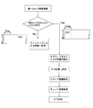
疵有り材料8のチャッキング部における疵の有無による作業の流れの一例を図5に示す。
【0029】
このように疵毎に疵周方向位置を特定しながら研削を行なっていくことにより、材料の曲がりの影響やチャッキングによる材料のズレ等の影響もなく確実な疵取り作業が可能となった。
【0030】
また、回転型漏洩磁束探傷機4による疵データ採取時に材料1のねじれ走行による周方向の位置ズレについても従来の原点マーク方式では対応できないが、本方式では疵毎に位置を特定でき研削可能となった。
【0031】
尚、本実施例における信号処理装置15の主な機能は、疵マップの作成・記憶、疵マップのトラッキング、疵探査機10の位置コントロール、研削機11の位置、研削条件のコントロールなどを一括して行なうことである。
【0032】
次に、本実施例の、複数個の疵がある場合の疵の周方向位置の特定方法について説明する。
【0033】
図6は本発明の疵照合方法の説明図である。
【0034】
図6(a)は第一の疵検査装置(すなわち回転型漏洩磁束探傷機4)における円周方向の疵分布で疵研削機11の研削幅を目安に円周16分割したマップ上に疵の有無が記されており、この場合A、B、Cと3ケ所の疵が探傷されている。それを第二の疵検査装置(すなわち疵探査機10)で探傷した結果、図4(b)のような分布D、E、Fのような結果となったとする。この図6(a)の疵マップと図6(b)の疵マップを16分割した区分(1区分22.5度)ピッチで時計方向に回転させ疵位置を照合させていく。例えばこの場合θ1=θ3、θ2≠θ4なので各疵の一致照合状況は下記のようになる。
【0035】
(1)疵Aと疵Dが一致した時 B=E C≠F
(2)疵Aと疵Eが一致した時 B≠F C≠A
(3)疵Aと疵Fが一致した時 B≠D C≠E
これらのうち二カ所以上の一致した場合を研削可とし、この場合A=D、B=Eとして研削を行うように判断させる。
【0036】
このように第一の疵検査装置による探傷データ疵位置情報として、周方向には周方向研削幅以下に分割した疵位置情報を移送し、第二の疵検査装置による周方向複数個の疵位置関係(疵間角度差)の情報を照合し、一致した部分を研削用にすることにより、信頼性の高い自動疵取り作業が可能となった。
【0037】
【発明の効果】
従来不可能であった高速自動表面疵検査装置と自動研削機を連動させた表面疵除去作業の自動化が可能となった。これにより従来オペレーターの熟練を要する磁粉探傷による疵見作業・疵除去作業が不要となり、またこれら人の技量に依存していた官能検査、手動疵取り作業が機械化され、見落としなどの作業ミスが軽減され、製品の品質向上に寄与するところ大となった。
【0038】
さらに、複数個疵が存在し、更に第一の疵検査装置での疵信号分布と第二の疵検査装置の疵信号分布と一致しない場合であっても、自動研削の位置ずれを起こすことなく、より信頼性の高い自動疵取りシステムの提供が可能となった。
【図面の簡単な説明】
【図1】疵探査における、疵の位置情報(疵マップ)の一例を示す図。
【図2】疵探査における、疵の信号レベル及びノイズ信号レベルと判定レベルとの関係を示す図。
【図3】本願発明の一実施例を示すレイアウト図。
【図4】疵有り材料とチャッキング装置およびクランプ装置の関係を示す図。
【図5】疵有り材料のチャッキング部における疵の有無による作業の流れの一例を示すフローチャート。
【図6】本願発明の一実施例の第二の疵周方向位置情報と第一の疵周方向位置情報の照合方法の一例を示す説明図。
【符号の説明】
1…材料(丸棒鋼)[ワーク]
2…デバリングテーブル
3…検査テーブル
4…回転型漏洩磁束探傷機
5…マーキング装置
6…回転超音波探傷機
7…疵無し材料(合格材、手入れ不要材)
8…疵有り材料(不合格材、手入れ要材)
9…研削テーブル
10…疵探査機
11…自動研削機
12…チャッキング装置
13…材料回転装置
14…跳ね出しテーブル
15…信号処理装置
16…クランプ装置[0001]
BACKGROUND OF THE INVENTION
The present invention is a method for automatically cutting a long material, in which a surface flaw of a long material such as a round steel bar or a steel pipe is inspected by a full cross-section flaw inspection device and is automatically ground based on the flaw position information of the selected flawed material. About. In particular, the present invention relates to an automatic material cutting method for a long material, which enables quick and accurate automatic paper cutting regardless of the position of the material in the long material.
[0002]
[Prior art]
As this type of prior art, there is, for example, Japanese Patent Publication No. 52-15054 “A method for defining the wrinkle position in a separation type automatic picking apparatus”.
[0003]
In this method, the wrinkle inspection device and the grinding machine are separated from each other, and a reference point such as a label that can be detected by optical means is provided on the material to be processed at the time of inspection, and is detected by an optical detector during grinding. The grinding position of the grinding machine is controlled based on the reference.
[0004]
[Problems to be solved by the invention]
As in the example shown in the above-mentioned “prior art”, a method of attaching a label to a test material such as a round steel bar or spraying a quick-drying ink or paint is actually inaccurate with various positions. It was never enough in terms of accuracy with respect to the wrinkle pattern. In particular, it has been difficult to apply to a material having a high flaw detection speed (for example, 100 m / min or more) line or a small-diameter bend.
[0005]
In addition, there may be an ultrasonic flaw detector that uses water immediately after the surface inspection device, and in such a line configuration, label detachment, marking blurring, etc. occur, and the accuracy and certainty of the origin position are improved. It is difficult to apply to the required automatic scraping device.
[0006]
In addition, during flaw detection, the material may twist and run due to wear of the transport roll, etc. When the reference mark is one location, the position information map of the flaw becomes inaccurate and causes a position shift of automatic grinding.
[0007]
[Means for Solving the Problems]
This invention solves the said subject and provides the automatic picking line of the elongate material which can perform a quick and accurate automatic picking, The summary is as a claim. That is: The surface defects of long materials such as round steel bars and steel pipes are inspected with a full cross-section defect inspection device, and the material with defects and the defect-free material are selected. Longitudinal position information is stored in the storage device, tracking processing is performed in the order of materials, and when the wrinkled material reaches the wrinkled grinding position, the circumferential wrinkle probe directly connected to the grinder is Based on the wrinkle longitudinal direction position information stored in the storage device, it moves to the longitudinal wrinkle coordinate position of the wrinkled material, further chucks and rotates one end portion of the wrinkled material, and The position in the circumferential direction is specified by a probe, and then the material with crease is fixed with a chucking device, and then the material with crease in the chucking part is separated from the material without crease, Place Automatically grinds the wrinkles based on the specified wrinkle position information while being chucked, and in the case of a material having wrinkles in the chucking portion, when grinding the wrinkles in the chucking portion, the material is removed by a clamping device. After supporting , the chucking device is removed, the chuck is released from the ridge, and the ridge is automatically ground to automatically grind the long material.
[0008]
2. The surface defects of long materials such as round steel bars and steel pipes are inspected with a full cross-section defect inspection device, and the material with defects and the defect-free material are selected. Longitudinal position information and first circumferential direction position information are stored in a storage device, tracking processing is performed in the order of materials, and then when the material with ridges reaches the heel grinding position, the circumferential direction ridge directly connected to the grinding machine The probe is moved to the longitudinal coordinate position of the wrinkled material based on the wrinkle longitudinal position information stored in the storage device for the wrinkled material, and one end of the wrinkled material is chucked. The second circumferential direction position information is obtained by the circumferential direction dredger, and the second circumferential direction position information is compared with the first circumferential direction position information stored in the storage device. and a matching portion grinding position Identify Te, then the flaw there materials were fixed in chucking device, then chucked portion free material and flaws there materials fractionated into, in the case of material flaws is not in the chucking section above while chucking In the case of a material having wrinkles in the chucking portion, the material is chucked after the material is supported by the clamp device when grinding the wrinkles in the chucking portion. A method for automatically removing a long material, wherein the apparatus is removed, the chuck is removed from the ridge and the ridge is automatically ground.
[0009]
It is.
[0010]
As the entire cross-sectional surface inspection apparatus used in the present invention, a leakage magnetic flux detection apparatus or an eddy current detection apparatus is used, and the sensor rotates and the material moves straight, and conversely the sensor rotates and the material rotates. There are forms, both of which are applicable.
[0011]
The wrinkle position information in the longitudinal direction of the wrinkles by this full-section wrinkle inspection device, or in addition, the wrinkle position information in the circumferential direction of the wrinkles is subjected to tracking processing in synchronization with the conveyance of the wrinkled material to the grinding table. Even if the wrinkle position information by this full cross section wrinkle inspection device is only the wrinkle position information in the longitudinal direction of the wrinkle as in the invention described in
[0012]
If the wrinkle position information finely divided in the circumferential direction is also taken together, the number distribution of wrinkles can be known in advance, and based on this information, it can be used as an information source for efficient grinding machine control.
[0013]
It is preferable to use a flaw detection apparatus having a flaw detection capability equivalent to that of a full-section flaw inspection apparatus for a circumferential flaw detection apparatus directly connected to a grinding machine. In addition, the automatic grinder and the circumferential wrinkle exploration machine are directly connected to each other, so that there is almost no mechanical misalignment between the exploration machine and the grinder, and the searched wrinkle can be reliably ground.
[0014]
When exploring the soot with a circumferential soot explorer directly connected to this grinding machine, one end of the material with the soot is chucked and rotated. Thereby, the circumferential direction position of a bag can be specified. However, the wrinkle position may overlap with the chucking portion of the material, and automatic grinding becomes difficult as it is.
[0015]
Therefore, in the present invention, the material with and without wrinkles in the chucking portion is separated, and in the case of the material without wrinkles in the chucking portion, the wrinkles are determined based on the specified wrinkle position information while being chucked. In the case of a material with wrinkles in the chucking part that is automatically ground, it is configured so that the wrinkles in the chucking part can be ground by supporting the material with a clamp device and releasing the chucking device to automatically grind the wrinkles It is.
[0016]
The present invention according to
[0017]
For example, when there are two or more wrinkles on the same circumference in the first hull circumferential direction position information (hull map) obtained by the full cross section wrinkle inspection device, the circumferential wrinkle probe directly connected to the grinding machine Is necessary to determine which of the first heel circumferential direction position information (the heel map) corresponds to each of the heels in the second heel circumferential direction position information. Since the reference point in the circumferential direction is not clear in the wrinkle map), it is necessary to collate with the relative position information of the respective wrinkles. If the discrimination is not appropriate, incorrect grinding will be performed.
[0018]
For example, when there are three wrinkles as shown in FIG. 1, when searching for the position of G, as shown in FIG. 2, the noise level (4) of the material skin is lower than the level of (3). When the signal is higher, (4) is judged as the third flaw and the wrong grinding is performed. Further, as shown in FIG. 2, the same applies to the case where the third defect is not found even if the determination level is gradually lowered from the normal determination level I to the determination level lower limit II by the computer.
[0019]
Therefore, we developed a method to collate the first circumferential direction position information obtained by the entire cross-sectional surface inspection apparatus with the second circumferential direction position information obtained by the circumferential direction surface exploration machine directly connected to the grinding machine. It is what.
[0020]
By configuring in this way, effective automatic scraping can be achieved.
[0021]
【Example】
FIG. 3 is a layout diagram showing an embodiment of the automatic picking method of the present invention.
[0022]
In this example, the present invention was applied to round steel bars Φ20 to Φ80. The
[0023]
The inspection speed of the inspection table 3 is as fast as 80 to 120 m / min, and since there is a rotating ultrasonic flaw detector 6 that uses water as a contact medium on the rear surface, accurate origin mark or labeling cannot be applied. The mark by the marking device 5 is for confirmation.
[0024]
The material that has passed the rotary leakage magnetic flux flaw detector 4 goes straight without jumping out as a wrinkle-free material (accepted material, maintenance unnecessary material) 7. In other words, only the ridged material (failed material, care required material) 8 is arranged in a line on the jumping table 14. The wrinkle-free material (accepted material, maintenance-unnecessary material) 7 is only required to pass through the grinding table 9, and it is not always necessary to sort good products and defective products.
[0025]
The wrinkle position information of the wrinkled material (rejected material, care required material) 8 is processed and stored by the
[0026]
That is, according to the hail map information stored in the
[0027]
If there are wrinkles in the chucking part, as shown in FIG. 4, the
[0028]
FIG. 5 shows an example of a work flow depending on the presence or absence of wrinkles in the chucking portion of the
[0029]
In this way, by performing grinding while specifying the circumferential direction position for each rod, it is possible to perform a reliable scraping operation without being affected by the bending of the material or the displacement of the material due to chucking.
[0030]
In addition, the position deviation in the circumferential direction due to the torsional travel of the
[0031]
The main functions of the
[0032]
Next, a method for specifying the circumferential position of the heel when there are a plurality of heels according to the present embodiment will be described.
[0033]
FIG. 6 is an explanatory diagram of the wrinkle matching method of the present invention.
[0034]
FIG. 6A shows the distribution of wrinkles on a map obtained by dividing the circumference by 16 with reference to the grinding width of the wrinkle grinder 11 by the wrinkle distribution in the circumferential direction in the first wrinkle inspection apparatus (that is, the rotary leakage magnetic flux flaw detector 4). The presence or absence is indicated, and in this case, A, B, C and three flaws are detected. As a result of flaw detection using the second flaw inspection apparatus (that is, the flaw detector 10), it is assumed that distributions D, E, and F as shown in FIG. 4B are obtained. The wrinkle map of FIG. 6 (a) and the wrinkle map of FIG. 6 (b) are rotated clockwise at 16 divisions (one section 22.5 degrees) and the wrinkle position is collated. For example, in this case, since θ1 = θ3 and θ2 ≠ θ4, the matching state of each bag is as follows.
[0035]
(1) When 疵 A and 疵 D match B = E C ≠ F
(2) When 疵 A and 疵 E coincide B ≠ FC ≠ A
(3) When 疵 A and 疵 F match B ≠ DC C ≠ E
If two or more of these coincide, grinding is possible, and in this case, it is determined to perform grinding with A = D and B = E.
[0036]
Thus, as the flaw detection data flaw position information by the first flaw inspection apparatus, the flaw position information divided into the circumferential grinding width or less is transferred in the circumferential direction, and the plurality of flaw positions in the circumferential direction by the second flaw inspection apparatus are transferred. By collating information on the relationship (gap angle difference) and using the matching part for grinding, highly reliable automatic scraping work became possible.
[0037]
【The invention's effect】
It has become possible to automate the surface wrinkle removal work, which has been impossible with conventional high-speed automatic surface wrinkle inspection devices and automatic grinding machines. This eliminates the need for conventional inspection and removal work by magnetic particle flaw detection, and the sensory inspection and manual removal work, which depended on the skills of these people, is mechanized, reducing errors such as oversight. As a result, it contributed to improving product quality.
[0038]
Furthermore, even when there are a plurality of wrinkles and the wrinkle signal distribution in the first wrinkle inspection device and the wrinkle signal distribution in the second wrinkle inspection device do not coincide with each other, the position of automatic grinding does not occur. As a result, it has become possible to provide a more reliable automatic scraping system.
[Brief description of the drawings]
FIG. 1 is a diagram showing an example of hail position information (hail map) in hail exploration.
FIG. 2 is a diagram showing a relationship between a signal level and noise signal level of a kite and a determination level in kite exploration.
FIG. 3 is a layout diagram showing an embodiment of the present invention.
FIG. 4 is a diagram showing a relationship between a wrinkled material, a chucking device, and a clamping device.
FIG. 5 is a flowchart showing an example of a work flow depending on the presence or absence of wrinkles in a chucking portion for wrinkled material.
FIG. 6 is an explanatory diagram showing an example of a method of collating second circumferential direction position information and first circumferential direction position information according to an embodiment of the present invention.
[Explanation of symbols]
1… Material (Round steel bar) [Workpiece]
2 ... Deburing table 3 ... Inspection table 4 ... Rotary leakage magnetic flux flaw detector 5 ... Marking device 6 ... Rotary ultrasonic flaw detector 7 ... Flawless material (accepted material, maintenance-free material)
8 ... Material with defects (failed materials, materials for care)
DESCRIPTION OF
Claims (2)
Priority Applications (1)
| Application Number | Priority Date | Filing Date | Title |
|---|---|---|---|
| JP9875698A JP3630552B2 (en) | 1998-04-10 | 1998-04-10 | Automatic stripping method for long materials |
Applications Claiming Priority (1)
| Application Number | Priority Date | Filing Date | Title |
|---|---|---|---|
| JP9875698A JP3630552B2 (en) | 1998-04-10 | 1998-04-10 | Automatic stripping method for long materials |
Publications (2)
| Publication Number | Publication Date |
|---|---|
| JPH11291151A JPH11291151A (en) | 1999-10-26 |
| JP3630552B2 true JP3630552B2 (en) | 2005-03-16 |
Family
ID=14228290
Family Applications (1)
| Application Number | Title | Priority Date | Filing Date |
|---|---|---|---|
| JP9875698A Expired - Lifetime JP3630552B2 (en) | 1998-04-10 | 1998-04-10 | Automatic stripping method for long materials |
Country Status (1)
| Country | Link |
|---|---|
| JP (1) | JP3630552B2 (en) |
Cited By (1)
| Publication number | Priority date | Publication date | Assignee | Title |
|---|---|---|---|---|
| WO2013125604A1 (en) | 2012-02-20 | 2013-08-29 | 株式会社応用ナノ粒子研究所 | Oxygen source-containing composite nanometal paste and joining method |
Families Citing this family (3)
| Publication number | Priority date | Publication date | Assignee | Title |
|---|---|---|---|---|
| CN104551956B (en) * | 2014-12-19 | 2017-01-04 | 新昌县科宇刃具机械有限公司 | A kind of diesel motor rockshaft pole stock automatically grinding equipment |
| JP6493340B2 (en) * | 2016-08-31 | 2019-04-03 | Jfeスチール株式会社 | Steel pipe maintenance guidance system |
| CN112589256B (en) * | 2020-12-02 | 2022-10-14 | 四川航天长征装备制造有限公司 | Planar weld seam trimming and detecting device and method |
-
1998
- 1998-04-10 JP JP9875698A patent/JP3630552B2/en not_active Expired - Lifetime
Cited By (1)
| Publication number | Priority date | Publication date | Assignee | Title |
|---|---|---|---|---|
| WO2013125604A1 (en) | 2012-02-20 | 2013-08-29 | 株式会社応用ナノ粒子研究所 | Oxygen source-containing composite nanometal paste and joining method |
Also Published As
| Publication number | Publication date |
|---|---|
| JPH11291151A (en) | 1999-10-26 |
Similar Documents
| Publication | Publication Date | Title |
|---|---|---|
| US4126491A (en) | Method and apparatus for producing metal blanks, in particular steel slabs, which at least in a predetermined surface area have substantially no defects | |
| CA2676748A1 (en) | Defect marking method and device | |
| US20060021208A1 (en) | Method for fastening a tool in a tool chuck | |
| JP2001041739A (en) | Automatic size measuring device with circularity measurement function | |
| US4633620A (en) | System for processing of steel billets or the like to remove surface defects | |
| JP3630552B2 (en) | Automatic stripping method for long materials | |
| JP2538712B2 (en) | Method and device for reshaping of railway wheels by cutting | |
| EP2168742A1 (en) | Stone cutting machine using a diamond disc | |
| US4112626A (en) | Automatic deseaming apparatus for elongate block of metallic material | |
| US6008891A (en) | Automatic flaw removing method for long materials | |
| JP3525047B2 (en) | Automatic material removal method for long materials | |
| JP2008200736A (en) | U-bend pipe marking method and online finishing equipment | |
| JP3663050B2 (en) | Automatic stripping method and stripping apparatus for long materials | |
| US3534258A (en) | Magnetic nondestructive testing system utilizing magnetic tapes with means to indicate flow depth | |
| CN216208302U (en) | Brinell hardness detection device | |
| JP7265139B2 (en) | Steel material surface layer inspection method and steel material surface layer inspection system | |
| JP2628278B2 (en) | Method and apparatus for removing flaws in linear material | |
| CN109607264A (en) | Granny rag method and its cloth-pulling device used | |
| JPH09300198A (en) | Defect information display method | |
| JPH10132509A (en) | Seam detection method for ERW steel pipe | |
| KR102488836B1 (en) | Apparatus for automating high frequency heat treatment for shaft | |
| JP2000117612A (en) | Method and apparatus for cleaning flaws on material to be ground | |
| JPH09210634A (en) | Long material measuring device | |
| CN108274243A (en) | The automatic chamfering machine of auto parts and components tubing | |
| JPS62226054A (en) | Discriminating device for defect of round steel |
Legal Events
| Date | Code | Title | Description |
|---|---|---|---|
| A977 | Report on retrieval |
Free format text: JAPANESE INTERMEDIATE CODE: A971007 Effective date: 20040318 |
|
| A131 | Notification of reasons for refusal |
Free format text: JAPANESE INTERMEDIATE CODE: A131 Effective date: 20040406 |
|
| A521 | Written amendment |
Free format text: JAPANESE INTERMEDIATE CODE: A523 Effective date: 20040531 |
|
| TRDD | Decision of grant or rejection written | ||
| A01 | Written decision to grant a patent or to grant a registration (utility model) |
Free format text: JAPANESE INTERMEDIATE CODE: A01 Effective date: 20041124 |
|
| A61 | First payment of annual fees (during grant procedure) |
Free format text: JAPANESE INTERMEDIATE CODE: A61 Effective date: 20041214 |
|
| R150 | Certificate of patent or registration of utility model |
Free format text: JAPANESE INTERMEDIATE CODE: R150 |
|
| FPAY | Renewal fee payment (event date is renewal date of database) |
Free format text: PAYMENT UNTIL: 20081224 Year of fee payment: 4 |
|
| FPAY | Renewal fee payment (event date is renewal date of database) |
Free format text: PAYMENT UNTIL: 20081224 Year of fee payment: 4 |
|
| FPAY | Renewal fee payment (event date is renewal date of database) |
Free format text: PAYMENT UNTIL: 20091224 Year of fee payment: 5 |
|
| FPAY | Renewal fee payment (event date is renewal date of database) |
Free format text: PAYMENT UNTIL: 20101224 Year of fee payment: 6 |
|
| FPAY | Renewal fee payment (event date is renewal date of database) |
Free format text: PAYMENT UNTIL: 20111224 Year of fee payment: 7 |
|
| FPAY | Renewal fee payment (event date is renewal date of database) |
Free format text: PAYMENT UNTIL: 20111224 Year of fee payment: 7 |
|
| FPAY | Renewal fee payment (event date is renewal date of database) |
Free format text: PAYMENT UNTIL: 20121224 Year of fee payment: 8 |
|
| FPAY | Renewal fee payment (event date is renewal date of database) |
Free format text: PAYMENT UNTIL: 20121224 Year of fee payment: 8 |
|
| FPAY | Renewal fee payment (event date is renewal date of database) |
Free format text: PAYMENT UNTIL: 20131224 Year of fee payment: 9 |
|
| R250 | Receipt of annual fees |
Free format text: JAPANESE INTERMEDIATE CODE: R250 |
|
| S111 | Request for change of ownership or part of ownership |
Free format text: JAPANESE INTERMEDIATE CODE: R313115 |
|
| R350 | Written notification of registration of transfer |
Free format text: JAPANESE INTERMEDIATE CODE: R350 |
|
| R250 | Receipt of annual fees |
Free format text: JAPANESE INTERMEDIATE CODE: R250 |
|
| R250 | Receipt of annual fees |
Free format text: JAPANESE INTERMEDIATE CODE: R250 |
|
| R250 | Receipt of annual fees |
Free format text: JAPANESE INTERMEDIATE CODE: R250 |
|
| EXPY | Cancellation because of completion of term |