JP3629193B2 - Insulating member, motor stator, and method of assembling motor stator - Google Patents
Insulating member, motor stator, and method of assembling motor stator Download PDFInfo
- Publication number
- JP3629193B2 JP3629193B2 JP2000286531A JP2000286531A JP3629193B2 JP 3629193 B2 JP3629193 B2 JP 3629193B2 JP 2000286531 A JP2000286531 A JP 2000286531A JP 2000286531 A JP2000286531 A JP 2000286531A JP 3629193 B2 JP3629193 B2 JP 3629193B2
- Authority
- JP
- Japan
- Prior art keywords
- insulating member
- teeth
- stator core
- motor stator
- tooth
- Prior art date
- Legal status (The legal status is an assumption and is not a legal conclusion. Google has not performed a legal analysis and makes no representation as to the accuracy of the status listed.)
- Expired - Lifetime
Links
Images


Description
【0001】
【発明の属する技術分野】
この発明は、巻線と固定子鉄心間の絶縁に、樹脂成形された絶縁部材を用いる電動機固定子に関するものである。
【0002】
【従来の技術】
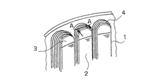
図8は従来の樹脂成形された絶縁部材を用いた電動機固定子の斜視図である。図において、1は固定子鉄心、2は固定子鉄心ティース部であり、この固定子鉄心ティース部2に樹脂成形された絶縁部材3を挿入して装着し、絶縁部材3の巻装部に巻線4を巻回してある。
【0003】
図9に図8のA−A面から見た固定子鉄心ティース部2と絶縁部材3の断面図を示す。図において、図8と同一部品には同一符号を付し説明を省略する。樹脂成形された絶縁部材3は、固定子鉄心ティース部2の上下から挿入されるよう2つ以上の部品から構成されている。また、絶縁部材挿入始端5は固定子鉄心ティース部2に挿入するように開口しており、絶縁部材挿入終端6まで挿入される。
【0004】
従来絶縁部材の寸法は、絶縁部材挿入始端開口巾をa、絶縁部材挿入終端開口巾b、固定子鉄心ティース巾をcとすると、絶縁部材3の挿入性を良くするため、a=b≧cとなるよう設計していた。ここで、7は絶縁部材座面部、8は絶縁部材ティース側面部、9は固定子鉄心端面部を示す。
【0005】
【発明が解決しようとする課題】
従来の電動機固定子は以上のように構成されているので、固定子鉄心ティース巾cに対し、絶縁部材挿入始端開口巾a及び絶縁部材挿入終端開口巾bが広いため、絶縁部材3と固定子鉄心ティース部2との密着性が悪く、固定子のスロット有効溝断面積が低下する為、1スロットに巻回される巻線の量が低下し、モータ効率が低下するという問題点があった。
【0006】
また、絶縁部材3は樹脂成形されている為、成形型で直角となるよう設計しても、成型品では角部が若干曲面になるという傾向があり、絶縁部材座面部7と絶縁部材ティース側面部8の交わる角部に若干の曲面が形成されてしまう。この為、座面での開口巾は曲面の分だけ小さくなり、絶縁部材3挿入時、絶縁部材座面部7が固定子鉄心端面部9に密着せず、巻線の周長が長くなりモータ効率が低下するという問題点があった。
【0007】
また、絶縁部材3を固定子鉄心ティース部2に挿入する際、固定子鉄心ティース巾cに対し、絶縁部材挿入始端開口巾a及び絶縁部材挿入終端開口巾bが広いため、製造ラインにおいて、挿入後巻線を実施するまでの間で絶縁部材3が脱落しやすいという問題点があった。
【0008】
また、絶縁部材3と固定子鉄心ティース部2の密着性を上げるため、a=b=cに近づけると絶縁部材3挿入時に、絶縁部材挿入終端6付近に応力が集中し、破損するという問題点があった。
【0009】
この発明は、かかる問題点を解決するためになされたもので、絶縁部材と固定子鉄心ティース部との密着性を向上し、銅損低減によりモータ効率を改善すると共に、絶縁部材の破損を防止し、製造ラインでの絶縁部材脱落を防止した、性能、信頼性、作業性を向上した電動機固定子を提供することを目的とする。
【0010】
【課題を解決するための手段】
この発明に係る絶縁部材は、電動機固定子鉄心の各ティース部に軸方向に分割して挿入され、挿入始端が前記ティース部に挿入するように開口し、挿入終端まで挿入される絶縁部材において、挿入始端の開口巾が、電動機固定子鉄心のティース巾よりも狭いものである。
【0011】
また、挿入始端の開口巾が電動機固定子鉄心のティース巾よりも狭く、挿入終端の開口巾が電動機固定子鉄心のティース巾よりも広いものである。
【0012】
また、電動機固定子鉄心の各ティース部に軸方向に分割して挿入され、挿入始端がティース部に挿入するように開口し、挿入終端まで挿入され、ティース部と対向する座面部と、ティース部の側面と対向するティース側面部とを有する絶縁部材において、座面部に、ティース側面部と接する面を有する溝を設けたものである。
【0013】
また、樹脂成形する際の成形型の合わせ部を、座面部と同一面上に設けたものである。
【0014】
また、複数のティース部に対し、1個又は複数個のティース部毎に分割し挿入するものである。
【0015】
この発明に係る電動機固定子の組立方法は、請求項1又は請求項2記載の絶縁部材を用いる電動機固定子の組立方法であって、テーパー状の治具を電動機固定子鉄心のティース部が挿入される隙間の中程に挿入し、絶縁部材の挿入始端開口部をティース巾より広げ、絶縁部材の挿入始端が挿入された後にテーパー状の治具を引き抜き、絶縁部材を絶縁部材の挿入終端まで挿入するものである。
【0016】
この発明に係る電動機固定子は、複数のティース部を有する固定子鉄心と、この固定子鉄心のティース部に挿入され、コイル巻装部を有する樹脂成形の請求項1〜5の何れかに記載の絶縁部材と、ティース部に装着された絶縁部材の巻装部に巻回される電線と、を備えたものである。
【0017】
【発明の実施の形態】
実施の形態1.
以下、この発明の実施の形態1を図面を用いて説明する。
図1は実施の形態1を示す図で、固定子鉄心ティース部と絶縁部材の断面図である。図において、樹脂成形された絶縁部材3は、固定子鉄心ティース部2の上下から挿入されるよう2つ以上の部品から構成されている。また、絶縁部材挿入始端5は固定子鉄心ティース部2に挿入するように開口しており、絶縁部材挿入終端6まで挿入される。7は絶縁部材座面部、8は絶縁部材ティース側面部、9は固定子鉄心端面部を示す。
【0018】
絶縁部材の寸法は、絶縁部材挿入始端開口巾をa、固定子鉄心ティース巾をcとすると、本実施の形態では、a<cとなるように設計する。
本実施の形態ではこれにより、絶縁部材3は固定子鉄心ティース部2に挿入された後も、絶縁部材挿入始端5開口部の復元力により固定子鉄心ティース部2に密着し、スロット有効溝断面積を広げることが可能となると共に、固定子製作時の絶縁部材3の脱落を防止するように作用する。
【0019】
なお、絶縁部材3の固定子鉄心ティース部2への挿入時には、本実施の形態では絶縁部材挿入始端5開口部をティース巾よりも広げる必要があるため、テーパー状の治具を固定子鉄心ティース部2が挿入される隙間の中程に挿入し、絶縁部材挿入始端5開口部をティース巾より広げ、絶縁部材挿入始端5が挿入された後に治具を引き抜き、絶縁部材3を絶縁部材挿入終端6まで挿入している。
【0020】
実施の形態2.
以下、この発明の実施の形態2を図面を用いて説明する。
図2は実施の形態2を示す図で、固定子鉄心ティース部と絶縁部材の断面図である。図において、絶縁部材挿入始端開口巾をa、絶縁部材挿入終端開口巾をb、固定子鉄心ティース巾をcとすると、本実施の形態ではa<c<bとなるように設計する。これにより、絶縁部材ティース側面部8が固定子鉄心ティース部2に接触する位置が、絶縁部材座面部7と絶縁部材ティース側面部8の交わる角部から離れた位置にすることが出来るため、前記角部の応力を緩和することができ、絶縁部材3の破損を防ぐことが出来る。
【0021】
この応力集中をCAE解析した結果を図3に示す。図3(a)はb=cとした場合の応力集中のCAE解析結果、図3(b)はb>cとした場合の応力集中のCAE解析結果を示す。これは絶縁部材3の絶縁部材座面部7と絶縁部材ティース側面部8の交わる付近を示したものであり、図3(a)に示すようにb=cとした場合の最大応力は、応力集中部10で示すように丁度絶縁部材座面部7と絶縁部材ティース側面部8が交わる角部で発生している。
【0022】
図3(b)に示すように、b>cとすることにより絶縁部材ティース側面部8が固定子鉄心ティース部2に接触する位置をコア積厚の3%程度絶縁部材座面部7より離れた位置にずらすことで、応力集中部10が前記接触する点に移ると共に、最大応力が77%まで緩和している。
【0023】
実施の形態3.
以下、この発明の実施の形態3を図面を用いて説明する。
図4は実施の形態3を示す図で、固定子鉄心ティース部と絶縁部材の断面図である。図において、図1と同一部分については同一符号を付している。本実施の形態は、絶縁部材座面部7に絶縁部材ティース側面部8と接する面を持つ絶縁部材座面溝部11を設けたものである。これにより、絶縁部材座面部7と絶縁部材ティース側面部8のなす角に、樹脂成形の際意図せずに生じてしまう若干の曲面により、絶縁部材座面部7での開口巾が曲面の分だけ狭くなることを防止し、設計通り絶縁部材座面部7でも開口巾がティース巾以上となる為、絶縁部材座面部7が固定子鉄心端面部9に密着することが可能になり、絶縁部材巻装部に巻回する巻線の周長を短くすることができ、モータ効率を改善することが出来る。
【0024】
また、1つのティースに1つのコイルを巻回する集中直巻タイプの巻線では、絶縁部材と固定子鉄心が密着することにより、巻装部が安定した形状となることから、巻線の整列性を高めることができ、スロットの巻線占有率を向上が可能となり、モータ効率の改善をすることができる。
【0025】
実施の形態4.
以下、この発明の実施の形態4を図面を用いて説明する。
図5は実施の形態4を示す図で、固定子鉄心ティース部と絶縁部材の断面図である。図において、図1と同一部分については同一符号を付している。本実施の形態は実施の形態3に対し、絶縁部材3を樹脂成形する際に発生する成形型合わせ部12を、絶縁部材座面部7と同一面上に配置したものである。
【0026】
成形型は形状により型の抜き方向が制限されるため、成形型の合わせ目を任意の場所に配置すると、成形型の形状が複雑となり高価なものとなってしまう。絶縁部材3は、固定子鉄心内部に挿入され、スロット内部を絶縁する直線的な部分と、固定子鉄心外部で巻線のコイルエンド部を保持し、巻線の渡り線や中性点、リード線等を納める複雑に入り組んだ形状を形作る部分とから形成される。
【0027】
この境目、つまり絶縁部材座面部7と同一面を成形型の合わせ目とすることで、成形型のコストを安価にすることが可能であるが、成形部品の場合、成形型の合わせ目はその他の部分に比べ強度が弱く、破損しやすいという問題がある。実施の形態2で述べた通り、絶縁部材座面部7と絶縁部材ティース側面部8の交わる点は、応力が最も集中する箇所である。
【0028】
そこで、実施の形態3で示した構造と併用することで最大応力点をずらし、成形型の合わせ目を座面と同一面に持ってきても、型の合わせ目に発生する応力を緩和することができ、絶縁部材3の歩留まりと信頼性を向上することができる。
【0029】
図6にCAE解析の結果を示す。これは、絶縁部材座面部7と絶縁部材ティース側面部8の交わる点付近を拡大したものである。図6(a)は角部の形状を成形型で直角とした場合に、実際に成形したもので実測した曲面で応力を計算したものである。図6(b)は座面に絶縁部材座面溝部11を設けた場合の応力を計算したものである。この結果、応力集中部10が絶縁部材座面溝部11側に移動し、絶縁部材座面部7と同一面に発生する応力は80%程度まで緩和されている。
【0030】
本実施の形態は、絶縁部材座面溝部11丸溝で示したが、角形状でも同様な効果は得られることは言うまでもない。
【0031】
実施の形態5.
以下、この発明の実施の形態5を図面を用いて説明する。
図7は実施の形態5を示す図で、絶縁部材の斜視図である。図において、1は1は固定子鉄心、2は固定子鉄心ティース部、3は固定子鉄心ティース部2に装着される樹脂成形された絶縁部材である。
【0032】
本実施の形態は、各ティース毎に一対の絶縁部材3を使用している。これにより、絶縁部材3挿入時に挿入始端開口部を広げる為の設備が少なくてすむため、設備投資の抑制に効果的である。
【0033】
本実施の形態は、1ティース毎に分割した例を示したが、2ティース以上を1まとまりとして分割しても同様の効果は得られるのは言うまでもない。
【0034】
【発明の効果】
この発明に係る絶縁部材は、挿入始端の開口巾を電動機固定子鉄心のティース巾よりも狭くしたことにより、絶縁部材はティース部に挿入された後も、挿入始端開口部の復元力によりティース部に密着し、スロット有効溝断面積を広げることが可能となると共に、固定子製作時の絶縁部材の脱落を抑制する効果を奏する。
【0035】
また、挿入始端の開口巾が電動機固定子鉄心のティース巾よりも狭く、挿入終端の開口巾が電動機固定子鉄心のティース巾よりも広くしたことにより、応力集中部を絶縁部材の座面部より離れた位置にずらすことができると共に、最大応力を低減することができる。
【0036】
また、座面部に、ティース側面部と接する面を有する溝を設けたことにより、座面部でも開口巾がティース巾以上となる為、座面部が固定子鉄心端面部に密着することが可能になり、絶縁部材巻装部に巻回する巻線の周長を短くすることができる。
【0037】
また、樹脂成形する際の成形型の合わせ部を、座面部と同一面上に設けたことにより、成形型の合わせ目を座面と同一面に持ってきても、型の合わせ目に発生する応力を緩和することができ、絶縁部材の歩留まりと信頼性を向上することができる。
【0038】
また、複数のティース部に対し、1個又は複数個のティース部毎に分割し挿入することにより、絶縁部材の挿入時に挿入始端開口部を広げる為の設備が少なくてすむため、設備投資の抑制に効果がある。
【0039】
この発明に係る電動機固定子の組立方法は、請求項1又は請求項2記載の絶縁部材を用いる電動機固定子の組立方法であって、テーパー状の治具を電動機固定子鉄心のティース部が挿入される隙間の中程に挿入し、絶縁部材の挿入始端開口部をティース巾より広げ、絶縁部材の挿入始端が挿入された後にテーパー状の治具を引き抜き、絶縁部材を絶縁部材の挿入終端まで挿入することにより、挿入始端の開口巾を電動機固定子鉄心のティース巾よりも狭くしたものであも、容易に組立を行うことができる。
【0040】
この発明に係る電動機固定子は、複数のティース部を有する固定子鉄心と、この固定子鉄心のティース部に挿入され、コイル巻装部を有する樹脂成形の請求項1〜5の何れかに記載の絶縁部材と、ティース部に装着された絶縁部材の巻装部に巻回される電線と、を備えたことにより、絶縁部材と固定子鉄心ティース部との密着性が向上し、モータ効率を改善すると共に、絶縁部材の信頼性向上、制作時の作業性向上、設備投資の抑制した電動機固定子を提供することができる。
【図面の簡単な説明】
【図1】実施の形態1を示す図で、絶縁部材及び固定子鉄心ティース部の断面図である。
【図2】実施の形態2を示す図で、絶縁部材及び固定子鉄心ティース部の断面図である。
【図3】実施の形態2を示す図で、CAE応力解析結果を示す図である。
【図4】実施の形態3を示す図で、絶縁部材及び固定子鉄心ティース部の断面図である。
【図5】実施の形態4を示す図で、絶縁部材の斜視図である。
【図6】実施の形態4を示す図で、CAE応力解析結果を示す図である。
【図7】実施の形態5を示す図で、絶縁部材及び固定子鉄心の斜視図である。
【図8】従来の電動機固定子の斜視図である。
【図9】従来の絶縁部材及び固定子鉄心ティース部の断面図である。
【符号の説明】
1 固定子鉄心、2 固定子鉄心ティース部、3 絶縁部材、4 巻線、5 絶縁部材挿入始端、6 絶縁部材挿入終端、7 絶縁部材座面部、8 絶縁部材ティース側面部、9 固定子鉄心端面部、10 応力集中部、11 絶縁部材座面溝部、12 成形型合わせ部。[0001]
BACKGROUND OF THE INVENTION
The present invention relates to an electric motor stator that uses a resin-molded insulating member for insulation between a winding and a stator core.
[0002]
[Prior art]
FIG. 8 is a perspective view of an electric motor stator using a conventional resin-molded insulating member. In the figure,
[0003]
FIG. 9 shows a cross-sectional view of the stator
[0004]
The dimensions of the conventional insulating member are: a = b ≧ c in order to improve the insertability of the insulating
[0005]
[Problems to be solved by the invention]
Since the conventional motor stator is configured as described above, the insulating member insertion start opening width a and the insulating member insertion end opening width b are wider than the stator core teeth width c. There is a problem in that the adhesion with the iron
[0006]
Further, since the insulating
[0007]
Further, when the insulating
[0008]
Further, in order to improve the adhesion between the
[0009]
The present invention has been made to solve such problems, and improves the adhesion between the insulating member and the stator core teeth, improves the motor efficiency by reducing copper loss, and prevents the insulating member from being damaged. It is another object of the present invention to provide an electric motor stator that has improved performance, reliability, and workability, and prevents an insulating member from dropping off in a production line.
[0010]
[Means for Solving the Problems]
The insulating member according to the present invention is inserted in each tooth portion of the motor stator core in an axial direction, opened so that the insertion start end is inserted into the tooth portion, and inserted to the insertion end. The opening width of the insertion start end is narrower than the teeth width of the motor stator core.
[0011]
Moreover, the opening width of the insertion start end is narrower than the teeth width of the motor stator core, and the opening width of the insertion end is wider than the teeth width of the motor stator core.
[0012]
Also, a seat surface portion that is inserted into each tooth portion of the motor stator core in an axial direction, opened so that the insertion start end is inserted into the tooth portion, inserted to the insertion end, and faces the teeth portion, and the tooth portion. In the insulating member having the side surface portion of the teeth and the side surface portion of the tooth facing the groove, the seat surface portion is provided with a groove having a surface in contact with the side surface portion of the tooth.
[0013]
Further, the mating portion of the mold for resin molding is provided on the same surface as the seat surface portion.
[0014]
Moreover, it divides | segments and inserts into every one or several teeth part with respect to several teeth part.
[0015]
An electric motor stator assembling method according to the present invention is an electric motor stator assembling method using the insulating member according to
[0016]
The electric motor stator according to the present invention is a resin core having a stator core having a plurality of tooth portions and a resin molding having a coil winding portion inserted into the teeth portion of the stator core. And an electric wire wound around the winding portion of the insulating member attached to the tooth portion.
[0017]
DETAILED DESCRIPTION OF THE INVENTION
FIG. 1 is a diagram showing the first embodiment, and is a cross-sectional view of a stator core tooth portion and an insulating member. In the figure, the resin-molded insulating
[0018]
The dimensions of the insulating member are designed so that a <c in the present embodiment, where a is the opening width of the insulating member insertion start end and c is the stator core teeth width.
Thus, in this embodiment, even after the insulating
[0019]
When the insulating
[0020]
FIG. 2 is a diagram showing the second embodiment, and is a cross-sectional view of a stator core tooth portion and an insulating member. In the drawing, when the insulating member insertion start end opening width is a, the insulating member insertion end opening width is b, and the stator core teeth width is c, in this embodiment, the design is made such that a <c <b. Thereby, since the position where the insulating member tooth side surface portion 8 contacts the stator
[0021]
The result of CAE analysis of this stress concentration is shown in FIG. FIG. 3A shows a CAE analysis result of stress concentration when b = c, and FIG. 3B shows a CAE analysis result of stress concentration when b> c. This shows the vicinity where the insulating member seating surface portion 7 and the insulating member tooth side surface portion 8 of the insulating
[0022]
As shown in FIG. 3B, by setting b> c, the position where the insulating member tooth side surface portion 8 contacts the stator
[0023]
FIG. 4 is a diagram showing the third embodiment, and is a cross-sectional view of the stator core teeth portion and the insulating member. In the figure, the same parts as those in FIG. In this embodiment, the insulating member seating surface portion 7 is provided with the insulating member seating
[0024]
In addition, in the case of concentrated direct winding type, in which one coil is wound around one tooth, the winding part becomes stable due to the intimate contact between the insulating member and the stator core. Therefore, the slot occupancy ratio can be improved, and the motor efficiency can be improved.
[0025]
Embodiment 4 FIG.
Embodiment 4 of the present invention will be described below with reference to the drawings.
FIG. 5 is a diagram showing the fourth embodiment, and is a cross-sectional view of the stator core teeth portion and the insulating member. In the figure, the same parts as those in FIG. In contrast to the third embodiment, the present embodiment is such that the
[0026]
Since the shape of the molding die is limited by the shape, if the joint of the molding die is arranged at an arbitrary location, the shape of the molding die becomes complicated and expensive. The insulating
[0027]
By making this boundary, that is, the same surface as the insulating member seating surface portion 7 as the joint of the molding die, the cost of the molding die can be reduced. There is a problem that the strength is weaker than that of the part and is easily damaged. As described in the second embodiment, the point where the insulating member seat surface portion 7 and the insulating member tooth side surface portion 8 intersect is the place where stress is most concentrated.
[0028]
Therefore, by using together with the structure shown in the third embodiment, the maximum stress point is shifted, and even if the joint of the mold is brought on the same surface as the seating surface, the stress generated in the joint of the mold can be relieved. Thus, the yield and reliability of the insulating
[0029]
FIG. 6 shows the result of CAE analysis. This is an enlarged view of the vicinity of the point where the insulating member seat surface portion 7 and the insulating member tooth side surface portion 8 intersect. FIG. 6 (a) shows the stress calculated on a curved surface actually measured with an actually molded product when the shape of the corner is a right angle with a molding die. FIG. 6B shows the stress calculated when the insulating member
[0030]
In the present embodiment, the insulating member seating
[0031]
FIG. 7 is a diagram showing the fifth embodiment, and is a perspective view of an insulating member. In the figure,
[0032]
In the present embodiment, a pair of insulating
[0033]
In the present embodiment, an example is shown in which each tooth is divided, but it goes without saying that the same effect can be obtained even if two teeth or more are divided as one unit.
[0034]
【The invention's effect】
In the insulating member according to the present invention, the opening width of the insertion start end is made narrower than the teeth width of the motor stator core, so that the insulating member is inserted into the tooth portion and the teeth portion is restored by the restoring force of the insertion start end opening portion. It is possible to expand the effective slot cross-sectional area of the slot and to prevent the insulation member from falling off during the manufacture of the stator.
[0035]
In addition, since the opening width of the insertion start end is narrower than the teeth width of the motor stator core and the insertion end opening width is wider than the teeth width of the motor stator core, the stress concentration part is separated from the seat surface part of the insulating member. The maximum stress can be reduced.
[0036]
In addition, by providing a groove having a surface in contact with the side surface portion of the tooth on the seat surface portion, since the opening width of the seat surface portion is equal to or greater than the teeth width, the seat surface portion can be in close contact with the end surface portion of the stator core. The circumference of the winding wound around the insulating member winding portion can be shortened.
[0037]
In addition, since the mating part of the molding die for resin molding is provided on the same surface as the seating surface part, even if the joint of the molding die is brought on the same surface as the seating surface, it occurs at the joint of the mold. The stress can be relieved, and the yield and reliability of the insulating member can be improved.
[0038]
In addition, by dividing and inserting one or more teeth into a plurality of teeth, less equipment is required to widen the insertion opening at the time of insertion of the insulating member. Is effective.
[0039]
An electric motor stator assembling method according to the present invention is an electric motor stator assembling method using the insulating member according to
[0040]
The electric motor stator according to the present invention is a resin core having a stator core having a plurality of tooth portions and a resin molding having a coil winding portion inserted into the teeth portion of the stator core. The insulation member and the electric wire wound around the winding portion of the insulation member attached to the tooth portion, the adhesion between the insulation member and the stator core tooth portion is improved, and the motor efficiency is improved. In addition to improvement, it is possible to provide an electric motor stator with improved insulation member reliability, improved workability during production, and reduced capital investment.
[Brief description of the drawings]
FIG. 1 shows the first embodiment and is a cross-sectional view of an insulating member and a stator core tooth portion.
FIG. 2 is a diagram showing the second embodiment and is a cross-sectional view of an insulating member and a stator core tooth portion.
FIG. 3 is a diagram illustrating the second embodiment and is a diagram illustrating a CAE stress analysis result;
FIG. 4 shows the third embodiment and is a cross-sectional view of an insulating member and a stator core tooth portion.
FIG. 5 shows the fourth embodiment and is a perspective view of an insulating member.
FIG. 6 is a diagram showing a fourth embodiment and is a diagram showing a CAE stress analysis result.
FIG. 7 shows the fifth embodiment, and is a perspective view of an insulating member and a stator core.
FIG. 8 is a perspective view of a conventional electric motor stator.
FIG. 9 is a cross-sectional view of a conventional insulating member and stator core teeth.
[Explanation of symbols]
DESCRIPTION OF
Claims (7)
前記挿入始端の開口巾が、前記電動機固定子鉄心のティース巾よりも狭いことを特徴とする絶縁部材。In the insulating member inserted into the teeth portion of the motor stator core divided in the axial direction, opened so that the insertion start end is inserted into the teeth portion, and inserted to the insertion end.
An insulating member, wherein an opening width of the insertion start end is narrower than a teeth width of the electric motor stator core.
前記座面部に、前記ティース側面部と接する面を有する溝を設けたことを特徴とする絶縁部材。A seat surface portion that is inserted into each tooth portion of the stator core of the motor in an axial direction, is opened so that an insertion start end is inserted into the teeth portion, is inserted to the insertion end, and faces the teeth portion, and the teeth. In the insulating member having the side surface portion of the teeth and the side surface portion of the tooth facing the portion,
An insulating member, wherein a groove having a surface in contact with the tooth side surface portion is provided in the seat surface portion.
テーパー状の治具を電動機固定子鉄心のティース部が挿入される隙間の中程に挿入し、絶縁部材の挿入始端開口部をティース巾より広げ、絶縁部材の挿入始端が挿入された後に前記テーパー状の治具を引き抜き、絶縁部材を絶縁部材の挿入終端まで挿入することを特徴とする電動機固定子の組立方法。An assembly method of an electric motor stator using the insulating member according to claim 1 or 2,
Insert the taper-shaped jig into the middle of the gap where the teeth of the motor stator core are inserted, widen the insertion start opening of the insulating member beyond the width of the teeth, and insert the insulating member insertion start into the taper. A method of assembling an electric motor stator, wherein a jig is pulled out and an insulating member is inserted up to an insertion end of the insulating member.
この固定子鉄心のティース部に挿入され、コイル巻装部を有する樹脂成形の請求項1〜5の何れかに記載の絶縁部材と、
前記ティース部に装着された前記絶縁部材の巻装部に巻回される電線と、
を備えたことを特徴とする電動機固定子。A stator core having a plurality of teeth portions;
The insulating member according to any one of claims 1 to 5, wherein the insulating member is inserted into a teeth portion of the stator core and has a coil winding portion.
An electric wire wound around a winding portion of the insulating member attached to the teeth portion;
An electric motor stator characterized by comprising:
Priority Applications (1)
| Application Number | Priority Date | Filing Date | Title |
|---|---|---|---|
| JP2000286531A JP3629193B2 (en) | 2000-09-21 | 2000-09-21 | Insulating member, motor stator, and method of assembling motor stator |
Applications Claiming Priority (1)
| Application Number | Priority Date | Filing Date | Title |
|---|---|---|---|
| JP2000286531A JP3629193B2 (en) | 2000-09-21 | 2000-09-21 | Insulating member, motor stator, and method of assembling motor stator |
Publications (2)
| Publication Number | Publication Date |
|---|---|
| JP2002101590A JP2002101590A (en) | 2002-04-05 |
| JP3629193B2 true JP3629193B2 (en) | 2005-03-16 |
Family
ID=18770439
Family Applications (1)
| Application Number | Title | Priority Date | Filing Date |
|---|---|---|---|
| JP2000286531A Expired - Lifetime JP3629193B2 (en) | 2000-09-21 | 2000-09-21 | Insulating member, motor stator, and method of assembling motor stator |
Country Status (1)
| Country | Link |
|---|---|
| JP (1) | JP3629193B2 (en) |
Cited By (1)
| Publication number | Priority date | Publication date | Assignee | Title |
|---|---|---|---|---|
| US11973388B2 (en) | 2018-08-17 | 2024-04-30 | Kyb Corporation | Rotating electric machine, insulator, and assembly method therefor |
Families Citing this family (7)
| Publication number | Priority date | Publication date | Assignee | Title |
|---|---|---|---|---|
| JP4800061B2 (en) * | 2006-02-13 | 2011-10-26 | アイチエレック株式会社 | Electric motor |
| JP5113428B2 (en) * | 2007-05-31 | 2013-01-09 | 日本電産サンキョー株式会社 | Stator and motor |
| JP5234899B2 (en) * | 2007-09-04 | 2013-07-10 | 株式会社ミツバ | Insulator for electric motor |
| JP5526661B2 (en) * | 2009-09-01 | 2014-06-18 | 日産自動車株式会社 | Rotating electric machine and stator |
| JP5452177B2 (en) * | 2009-11-10 | 2014-03-26 | 株式会社ミツバ | Rotating electric machine |
| JP5678968B2 (en) | 2013-01-31 | 2015-03-04 | 株式会社安川電機 | Bobbins and rotating electrical machines |
| JP6739514B2 (en) * | 2016-03-02 | 2020-08-12 | 株式会社日立産機システム | Axial gap type rotating electric machine and bobbin for rotating electric machine stator |
-
2000
- 2000-09-21 JP JP2000286531A patent/JP3629193B2/en not_active Expired - Lifetime
Cited By (1)
| Publication number | Priority date | Publication date | Assignee | Title |
|---|---|---|---|---|
| US11973388B2 (en) | 2018-08-17 | 2024-04-30 | Kyb Corporation | Rotating electric machine, insulator, and assembly method therefor |
Also Published As
| Publication number | Publication date |
|---|---|
| JP2002101590A (en) | 2002-04-05 |
Similar Documents
| Publication | Publication Date | Title |
|---|---|---|
| US10566870B2 (en) | Motor and method of manufacturing the same | |
| KR100596901B1 (en) | Stator with teeth formed from a soft magnetic powder material | |
| JP4486678B2 (en) | Rotating motor armature, rotating motor and manufacturing method thereof | |
| US6218758B1 (en) | Stator of dynamo-electric machine | |
| US20080157610A1 (en) | Stator for inner rotor type mold brushless motor | |
| EP0917255A2 (en) | Connecting terminal for stator | |
| US7642687B2 (en) | Short-circuit member for a commutator and an armature | |
| US6646535B2 (en) | Magnetic core | |
| US11502575B2 (en) | Motor and air-conditioning apparatus | |
| CN102484399A (en) | Stator with separately manufactured tooth tips | |
| KR102076247B1 (en) | Electrical Contact | |
| JP3629193B2 (en) | Insulating member, motor stator, and method of assembling motor stator | |
| JP4344529B2 (en) | Stator core | |
| US20160301272A1 (en) | Stator for rotary electric machine | |
| JP2007089400A (en) | Stator of rotary electric machine | |
| JP3371918B2 (en) | Rotating electric machine stator | |
| CN113950788B (en) | Rotary electric machine | |
| JP2002209359A (en) | Stator of motor and its connection device | |
| JP5442585B2 (en) | Electric motor stator and method of manufacturing the same | |
| EP3566239B1 (en) | Thermally protected bobbin assembly | |
| JP5097919B2 (en) | Resolver stator lead wire connection structure | |
| JP6984027B2 (en) | Electric motor | |
| WO2019082679A1 (en) | Rotating electric machine, rotating electric machine manufacturing method, and stator | |
| CN220857712U (en) | Stator core assembly, motor and electric power steering system | |
| JP3832491B2 (en) | Molded motor |
Legal Events
| Date | Code | Title | Description |
|---|---|---|---|
| RD04 | Notification of resignation of power of attorney |
Free format text: JAPANESE INTERMEDIATE CODE: A7424 Effective date: 20040517 |
|
| RD04 | Notification of resignation of power of attorney |
Free format text: JAPANESE INTERMEDIATE CODE: A7424 Effective date: 20041018 |
|
| A977 | Report on retrieval |
Free format text: JAPANESE INTERMEDIATE CODE: A971007 Effective date: 20041104 |
|
| TRDD | Decision of grant or rejection written | ||
| A01 | Written decision to grant a patent or to grant a registration (utility model) |
Free format text: JAPANESE INTERMEDIATE CODE: A01 Effective date: 20041207 |
|
| A61 | First payment of annual fees (during grant procedure) |
Free format text: JAPANESE INTERMEDIATE CODE: A61 Effective date: 20041210 |
|
| R150 | Certificate of patent or registration of utility model |
Free format text: JAPANESE INTERMEDIATE CODE: R150 Ref document number: 3629193 Country of ref document: JP Free format text: JAPANESE INTERMEDIATE CODE: R150 |
|
| FPAY | Renewal fee payment (event date is renewal date of database) |
Free format text: PAYMENT UNTIL: 20071217 Year of fee payment: 3 |
|
| FPAY | Renewal fee payment (event date is renewal date of database) |
Free format text: PAYMENT UNTIL: 20081217 Year of fee payment: 4 |
|
| FPAY | Renewal fee payment (event date is renewal date of database) |
Free format text: PAYMENT UNTIL: 20091217 Year of fee payment: 5 |
|
| FPAY | Renewal fee payment (event date is renewal date of database) |
Free format text: PAYMENT UNTIL: 20091217 Year of fee payment: 5 |
|
| FPAY | Renewal fee payment (event date is renewal date of database) |
Free format text: PAYMENT UNTIL: 20101217 Year of fee payment: 6 |
|
| FPAY | Renewal fee payment (event date is renewal date of database) |
Free format text: PAYMENT UNTIL: 20111217 Year of fee payment: 7 |
|
| FPAY | Renewal fee payment (event date is renewal date of database) |
Free format text: PAYMENT UNTIL: 20111217 Year of fee payment: 7 |
|
| FPAY | Renewal fee payment (event date is renewal date of database) |
Free format text: PAYMENT UNTIL: 20121217 Year of fee payment: 8 |
|
| FPAY | Renewal fee payment (event date is renewal date of database) |
Free format text: PAYMENT UNTIL: 20121217 Year of fee payment: 8 |
|
| FPAY | Renewal fee payment (event date is renewal date of database) |
Free format text: PAYMENT UNTIL: 20131217 Year of fee payment: 9 |
|
| R250 | Receipt of annual fees |
Free format text: JAPANESE INTERMEDIATE CODE: R250 |
|
| R250 | Receipt of annual fees |
Free format text: JAPANESE INTERMEDIATE CODE: R250 |
|
| R250 | Receipt of annual fees |
Free format text: JAPANESE INTERMEDIATE CODE: R250 |
|
| R250 | Receipt of annual fees |
Free format text: JAPANESE INTERMEDIATE CODE: R250 |
|
| R250 | Receipt of annual fees |
Free format text: JAPANESE INTERMEDIATE CODE: R250 |
|
| EXPY | Cancellation because of completion of term |