JP3629089B2 - Weighing device - Google Patents
Weighing device Download PDFInfo
- Publication number
- JP3629089B2 JP3629089B2 JP07264196A JP7264196A JP3629089B2 JP 3629089 B2 JP3629089 B2 JP 3629089B2 JP 07264196 A JP07264196 A JP 07264196A JP 7264196 A JP7264196 A JP 7264196A JP 3629089 B2 JP3629089 B2 JP 3629089B2
- Authority
- JP
- Japan
- Prior art keywords
- gate
- hopper
- guide pin
- drive source
- guide
- Prior art date
- Legal status (The legal status is an assumption and is not a legal conclusion. Google has not performed a legal analysis and makes no representation as to the accuracy of the status listed.)
- Expired - Fee Related
Links
Images


Description
【0001】
【発明の属する技術分野】
本発明は、組合せ計量等の計量作業を行なう計量装置に関し、詳しくはこれに装備されたホッパのゲート開閉機構に関する。
【0002】
【従来の技術】
各種商品の自動計量に用いられる装置として、組合せ計量装置がある。この装置の多くは、図5に示すように、図示しない機台上に配置された支持台(40)の中央部に加振器(42)を介して分散テーブル(41)を配置し、分散テーブル(41)の周囲に別の加振器(44)を介して複数個の供給トラフ(43)を放射状に配置すると共に、各トラフ(43)の先端部下方にこのトラフ(43)と同数のプールホッパ(45)及び計量ホッパ(46)を上下に2段配置した構造である。
【0003】
この装置における計量手順は以下の通りである。すなわち、先ず分散テーブル(41)を加振器(42)で加振してテーブル(41)上の被計量物を各供給トラフ(43)に分散流入させると共に、これを加振器(44)で加振してトラフ(43)の下流側に搬送し、各トラフ(43)の先端から落下した被計量物を上段の各プールホッパ(45)内に収納する。次いで、プールホッパ(45)を選択的に開いてその内部の計量物を下段の計量ホッパ(46)に供給し、各計量ホッパ(46)に個別に設けたロードセル(図示省略)でその重量を計量する。次に各計量ホッパ(46)での計量値の組合せの中から合計重量が目標値に等しいか、目標値に最も近い最適な組合せを選定し、選定された組合せに対応する計量ホッパ(46)を開いて被計量物を一斉に排出する。これを計量ホッパ(46)の下方に配置した逆円錐状の集合シュート(47)で集め、包装工程等の次工程に搬送する。
【0004】
図6は、上述したプールホッパ(45)及び計量ホッパ(46)の一構造例である。同図(a)に示すように、これらのホッパ(45)(46)は、通常、角筒状の本体(50)と、その側面に設けたゲート軸(51)(51)で回転可能に枢支されたゲート(52)(52)とで構成される。両ゲート(52)は、ゲート軸(51)を中心として閉じ位置(a図)と開き位置(b図)との間を揺動し、本体(50)の下部開口を閉塞・開放する。従来では、このようなゲート(52)の開閉運動を、エアシリンダ(54)の進退運動を複数のリンク材からなるリンク機構(55)で揺動運動に変換して得ている。すなわち、開き動作時には、エアシリンダ(54)のピストンロッドを進出させ、駆動リンク(56)の押圧部(57)を押圧してゲート(52)を開き、閉じ動作時には、エアシリンダ(54)のピストンロッドを退入させてその先端部を押圧部(57)から離反させ、開き動作時に蓄勢したバネ(58)の弾性力を利用してゲート(52)を閉じるようにしている。
【0005】
【発明が解決しようとする課題】
ところで、この種の計量装置では、被計量物が食品類である場合が多く、食品衛生上、定期的な洗浄作業が欠かせない。そのため、従来では、プールホッパや計量ホッパをフレームに引っ掛けるようにして取付け、洗浄時にはこれらを簡単に取り外し可能とし、個々のホッパ並びに装置本体を入念に洗浄できるようにしている。
【0006】
ところが、従来装置では、ホッパを取り外す際にエアシリンダ(54)と、これに駆動される駆動リンク(56)との間でホッパ側の機構と装置本体側の機構とが分離される。そのため、取り外したホッパには多数のリンク材やバネ(58)が付属し、これらが邪魔になるためにホッパの洗浄作業が行ないにくくなる欠点があった。
【0007】
また、ホッパを取り外すと、バネ(58)の弾性力によりゲート(52)が閉じ状態に保持されるため、ゲート(52)の内面等を洗浄する際には、バネ(58)の弾性力に抗してゲート(52)を押し広げながら本体(50)内に手を差し入れて洗浄しなければならず、作業が面倒である。特に、ゲート(52)が全閉位置にあるとリンク中のトグル機構(59)がデッドポイントに達してセルフロックするため(図6(a)参照)、かかる洗浄作業がより一層困難化する。すなわち、作業者は、バネ(58)の弾性力に抗しながら押圧部(57)をホッパ側に押圧してロックを解除し、この状態に保持したままホッパ内に手を差し入れてゲート内面を洗浄するという極めて煩雑な作業を必要とする。従って、ユーザーサイドからの改善の要望も多かった。
【0008】
そこで、本発明では、洗浄労力を軽減することのできる計量装置の提供を目的とする。具体的には、洗浄時等において、ホッパを装置本体から取り外した際にも、ホッパにリンク機構やバネ等が付属せず、また、取り外し状態ではゲートに弾性力等が作用せず、ゲートがフリーとなって自由に動かすことのできる計量装置の提供を目的とする。
【0009】
【課題を解決するための手段】
上記目的を達成するため、本発明では、ホッパ本体の下部開口を開閉するゲートを有するホッパが装備された計量装置において、案内ピンと、この案内ピンと相対移動可能に係合する案内溝のうちの何れか一方をゲートに設け、他方を、前記一方がゲートの開閉中心軸に対して直交する方向に揺動するように回転駆動源の駆動軸に連結して、当該駆動軸の駆動でゲートを開閉させるようにした。
【0010】
このようにゲートの開き動作のみならず、閉じ動作をも回転駆動源の駆動力で行なうようにすれば、従来装置で必須であったバネが不要となる。その結果、洗浄時においてホッパを装置本体から取り外すと、ゲートが弾性力の作用しないフリー状態となるので、従来洗浄しにくかったゲートやホッパ本体の内面等の洗浄が容易に行なえるようになる。
【0011】
案内ピンを回転駆動源で駆動すると共に、案内溝を、当該溝内での案内ピンの相対移動方向がゲートの開閉中心軸と平行になるようにしてゲートに設ける。この時には、案内ピンを公転運動させるとよい。
【0012】
また、案内溝を回転駆動源で駆動すると共に、案内ピンを、その軸方向がゲートの開閉中心軸と平行になるようにしてゲートに設ける。この時には、案内溝を揺動運動させるとよい。
【0013】
【発明の実施の形態】
以下、本発明にかかる計量装置の実施形態を図1乃至図6及び図8に基づいて説明する。
【0014】
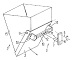
本発明では、ホッパ(1)の構成部品であるゲート(2)の開閉駆動源として、従来のエアシリンダの代わりにモータ等の回転駆動源(4:図3参照)を使用する。回転駆動源(4)とホッパ(1)との間には、回転駆動源(4)の駆動力をゲート(2)の閉じ動作及び開き動作に変換すべく、案内ピン(7)及び案内溝(11)からなる変換機構(3)が設けられる。
【0015】
回転駆動源(4)は、後述するように装置本体側の静止部材に固定され、その出力軸には図1に示すように、ホッパ(1)に向けて延びる駆動軸(5)が連結されている。この駆動軸(5)には、これと直交する方向に延びる連結腕(6)の一端部が固定され、さらに連結腕(6)の他端部に駆動軸(5)と平行に配置した案内ピン(7)が装着されている。回転駆動源(4)を起動して駆動軸(5)を回転させると、案内ピン(7)は駆動軸(5)を中心としてその周りを公転する。
【0016】
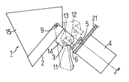
ゲート(2)の背面(ゲートの装置本体側の面であって、案内ピン(7)と対向する面)には、案内溝(11)が設けられる。この案内溝(11)は、ゲート(2)の開閉中心軸(9:ゲート軸)の軸芯方向に沿って上下に離隔配置したピン状の案内部(12)(13)間に形成される。案内溝(11)に挿入した案内ピン(7)は、案内部(12)(13)とその上下で係合し、且つ、ゲート軸(9)の軸芯方向に沿ってスライド可能である。両案内部(12)(13)は、ゲート(2)背面に装着した一対のブラケット(14)によって支持されている。
【0017】
案内溝(11)の幅寸法は、案内ピン(7)が挿入可能となる寸法であればよく、案内ピン(7)の直径以上であればよいが、より望ましくは案内ピン(7)との間に隙間が形成されないよう当該直径と同一寸法とする。また、案内部(12)(13)の長さは、案内ピン(7)の公転運動がブラケット(14)によって阻害されないよう、案内ピン(7)の公転直径以上に設定する。
【0018】
案内ピン(7)には、その公転中に常時双方の案内部(12)(13)と接触できるよう十分な長さを持たせる。具体的には、案内ピン(7)が何れの位置にあっても、その先端部が、案内部(12)(13)の揺動軌跡を越えてこれよりもホッパ(1)側に達する長さに設定する。また、案内ピン(7)が案内溝(11)内をゲート軸方向にスライドすると、ゲート(2)の開閉に伴って案内ピン(7)が当該スライド方向と直交する方向にも相対移動するので、かかる相対移動を許容できるよう案内ピン(7)の先端部と、ゲート(2)の背面との間にも十分な空間を確保しておく。
【0019】
さらに、案内ピン(7)は、その公転運動によって生じる押圧力が効率よくゲート(2)の開閉運動に変換されるよう、その軸方向を、ゲート軸(9)と上下の案内部(12)(13)とを結ぶ線に対してできるだけ平行に近付けて配置するのが望ましい。
【0020】
図4にホッパ(1)の取付け構造の一例を示す。図示のように、ホッパ(1)の本体(15)には、ゲート軸(9)の軸芯方向に離隔させて、一対の取付け部材(20)が固定される(図面では一方の取付け部材のみを図示している)。一方、装置本体側には、回転駆動源(4)を支持する支持基体(21)がロードセル(22)を介して装置本体の静止部材、例えば支持台(23)に釣り下げ状態で取付けられている。支持基体(21)には、両取付け部材(20)と同様にゲート軸(9)の軸芯方向に離隔させた一対の係止部材(24)が固定されており、この係止部材(24)の先端部には切欠き穴状の被係合部(25)がそれぞれ形成されている。両取付け部材(20)の側面には、上下に離隔させて突起状の係合部(26)(27)が形成されており、このうちの上方の係合部(26)は、係止部材(24)の被係合部(25)に嵌め込まれ、下方の係合部(27)は係止部材(24)の下端面を係止してホッパ(1)を所定の位置及び姿勢に位置決め保持している。
【0021】
この取付け構造であれば、支持基体(21)、回転駆動源(4)、ホッパ(1)、取付け部材(20)及び係止部材(24)の全ての重さがロードセル(22)に負荷されるので、この重さと被計量物を投入した後の全体の重さとを計測することにより、その差から被計量物の重量を検知することができる。
【0022】
以上の構成において、回転駆動源(4)を起動して案内ピン(7)を例えば時計回りに公転させると、先ず、案内ピン(7)が最下降位置(図3に実線及び破線で示す)から最上昇位置(二点鎖線で示す)に移動する間は、上方の案内部(12)が案内ピン(7)から上向きの押圧力を受ける。これにより、閉じ位置(実線で示す)にあるゲート(2)がゲート軸(9)を中心として開き方向に揺動する。これに伴い、案内部(12)(13)で上下を拘束された案内ピン(7)が、案内溝(11)内をその中心から、装置本体側から見て左側にスライドし、続いて逆方向にスライドして中心位置に戻る。案内ピン(7)が最上昇位置に達すると、ゲート(2)が全開状態(二点鎖線で示す)になる。
【0023】
次いで、回転駆動源を同方向に起動し、最上昇位置にある案内ピン(7)を最下降位置まで公転させると、下方の案内部(13)が案内ピン(7)から下向きの押圧力を受け、ゲート(2)が閉じ方向に揺動する。この時、案内ピン(7)は、案内溝(11)の中心部から右側にスライドし、やがて逆方向にスライドして中心位置に戻る。案内ピン(7)が最下降位置に達すると、ゲート(2)が完全に閉じる。この時、案内ピン(7)が最下降位置、すなわちデッドポイントにあってセルフロックされるので、仮に回転駆動源(4)を停止し、案内ピン(7)に何らの駆動力を付与しなくても、ゲート(2)をその内面側から押し開くことはできない。従って、ゲート(2)が被計量物の重みで勝手に開くことはなく、何ら特別な機構を追加しなくてもトグル機能を付与することができる。もちろんゲートが閉じた後も回転駆動源(4)を全閉直前と同方向に駆動して回転トルクを付与しても、同様のロック機能を付与することができる。
【0024】
回転駆動源(4)の起動及び停止は、その出力軸の回転数や回転角をエンコーダ等のセンサで読み取ることにより制御することができる。
【0025】
なお、ゲート(2)が完全に閉じる直前にその閉じ速度を減じるよう回転駆動源(4)を制御すれば、ゲート(2)がホッパ本体(15)と衝突することによって生じる騒音を緩和することができる。
【0026】
以上の説明では、案内ピン(7)を時計回りに公転させているが、反時計回りに公転させても全く同様の機能が奏される。また、案内ピン(7)が最下降位置から最上昇位置に至るまでの行程と最上昇位置から最下降位置に戻るまでの行程とで互いに逆方向に公転させてもよい。
【0027】
このように、本発明の構成であれば、リンク機構及びバネを用いることなくゲート(2)を開閉させることができ、しかもトグル機能も特に専用の機構を追加することなく簡単に付与できる。従って、取り外したホッパにはリンク機構やバネ等が付属せず、リンク機構等に邪魔されることなく、能率よくホッパ(1)を洗浄することができる。また、ホッパ(1)の軽量化も達成される。
【0028】
また、洗浄時において、ホッパ(1)を取り外す際には、図4に示すようにホッパ(1)を上方に引張っり、案内ピン(7)を案内部(12)(13)の間から抜き取ると共に、上方の係合部(26)を被係合部(25)から脱出させればよい。従って、極めて簡単な作業でホッパを分離することができる。この時、切欠き穴状の被係合部(25)が案内ピン(7)の軸方向と平行に形成されているので、案内ピン(7)の抜き取りと同時に係合部(26)の抜き取りがなされ、上記分離作業も簡単に行なうことができる。取り外し後のゲート(2)は、図4に示すように、外力の負荷されないフリー状態であり、自由に動かすことができるので、従来装置では洗浄しにくかったゲート(2)の内面(ホッパの内部に露出した面)も簡単且つ確実に洗浄することができる。
【0029】
図2に案内溝(11)の他の構成例を示す。図示のように、断面略コ字型に屈曲形成した板材に長穴を形成することによっても案内溝(11)を形成することができる。
【0030】
以上の説明では、案内ピン(7)を駆動側に配置し、案内溝(11)を被駆動側であるゲート(2)に設けた場合を例示したが、これとは逆に案内ピン(7)を被駆動側であるゲート(2)に設け、案内溝(11)を駆動側に設けてもよい。図7は、その一例であり、ゲート(2)背面にゲート軸(9)方向と平行に案内ピン(7)を配置すると共に、回転駆動源(図示省略)によって揺動駆動される揺動部材(30)の揺動端部に案内溝(11)に設けたものである。揺動部材(30)は、回転駆動源の駆動軸の回転運動をカム機構(31)で揺動運動に変換し、これを2つのリンク材(32)(33)で伝達することにより、枢軸(34)を中心として揺動駆動される。揺動部材(30)が揺動すると、案内溝(11)に係合させた案内ピン(7)が揺動部材(30)から押圧力を受け、ゲート(2)が実線位置と二点鎖線位置との間で開閉運動を行なう。
【0031】
なお、図1乃至図4及び図7では、1つのゲート(2)を有する片開き式のホッパを図示しているが、図6に示すような2つのゲートを有する両開き式のホッパにも同様の構成が適用可能である。この場合には、一方のゲートに図1乃至図4に示す開閉機構を適用し、他方のゲートを図6に示す連結リンク(60)を介して前記一方のゲートに連結すればよい。この他、2つのゲートのそれぞれに独立して上述の開閉機構を設置してもよい。また、上述のゲート開閉機構は、図5に示す計量装置のプールホッパ(45)及び計量ホッパ(46)の双方に適用可能である。
【0032】
【発明の効果】
このように本発明によれば、リンク機構及びバネを用いることなくゲートを開閉させることができ、トグル機能も特に専用の機構を追加することなく簡単に付与できる。従って、洗浄時においても取り外したホッパにリンク機構やバネ等が付属せず、リンク機構等に邪魔されることなく、能率よくホッパを洗浄することができる。しかも取り外したホッパは、ゲートが外力の負荷されないフリー状態であり、自由に動かすことができるので、従来装置では洗浄しにくかったゲートの内面も簡単且つ確実に洗浄できるようになる。また、ホッパの軽量化も達成され、さらに複雑なリンクやバネがないことからホッパ外観がすっきりし、塵埃等が付着しにくくなって洗浄頻度が低減する。
【0033】
また、モータ等の回転駆動源で駆動してゲートを閉じるため、閉じた瞬間にゲートがホッパ本体と衝突して生じる衝撃音を緩和することができる。すなわち、従来品では、ゲートの閉じ力をバネの弾性力で得ているため、ゲートの閉じ速度を制御することができず、慣性によりゲートが激しくホッパ本体に衝突して耳障りな騒音を生じていたが、本発明では、回転駆動源でゲートを閉じているため、閉じる直前に閉じ速度が減少するように回転駆動源を電気的に制御することができ、容易に騒音レベルの低下が図れる。
【図面の簡単な説明】
【図1】本発明にかかる計量装置に装備されたゲート開閉機構の斜視図である。
【図2】案内溝の他の実施形態を示す斜視図である。
【図3】図1に示すゲート開閉機構の側面図である。
【図4】図1に示すゲート開閉機構の側面図である。
【図5】一般的な計量装置の縦断面図である。
【図6】従来のゲート開閉機構の側面図である。
【図7】変換機構の他の実施形態を示す側面図である。
【符号の説明】
1 ホッパ
2 ゲート
3 変換機構
4 回転駆動源
7 案内ピン
9 開閉中心軸(ゲート軸)
11 案内溝
15 ホッパ本体[0001]
BACKGROUND OF THE INVENTION
The present invention relates to a weighing device that performs weighing operations such as combination weighing, and more particularly, to a gate opening / closing mechanism of a hopper equipped therein.
[0002]
[Prior art]
As a device used for automatic weighing of various products, there is a combination weighing device. As shown in FIG. 5, many of these apparatuses have a dispersion table (41) disposed through a vibration exciter (42) in the center of a support base (40) disposed on a machine base (not shown). A plurality of supply troughs (43) are arranged radially around the table (41) via another vibrator (44), and the same number of troughs (43) is provided below the tip of each trough (43). The pool hopper (45) and the weighing hopper (46) are arranged in two stages up and down.
[0003]
The weighing procedure in this device is as follows. That is, first, the dispersion table (41) is vibrated by the vibration exciter (42) so that the objects to be weighed on the table (41) are distributed and flown into the supply troughs (43), and the vibration distribution device (44). Then, the object to be weighed is transported to the downstream side of the trough (43) and dropped from the tip of each trough (43), and is stored in each pool hopper (45) on the upper stage. Next, the pool hopper (45) is selectively opened to supply the weighing item therein to the lower weighing hopper (46), and the weight is measured by a load cell (not shown) individually provided in each weighing hopper (46). Weigh. Next, an optimum combination with the total weight equal to or close to the target value is selected from the combination of the measured values in each weighing hopper (46), and the weighing hopper (46) corresponding to the selected combination is selected. Open and discharge the objects to be weighed all at once. This is collected by an inverted conical collecting chute (47) disposed below the weighing hopper (46) and conveyed to the next step such as a packaging step.
[0004]
FIG. 6 is a structural example of the pool hopper (45) and the weighing hopper (46) described above. As shown in FIG. 5A, these hoppers (45) and (46) are usually rotatable by a rectangular tube-shaped main body (50) and gate shafts (51) and (51) provided on the side surfaces thereof. It is composed of pivoted gates (52) and (52). Both gates (52) swing between a closed position (Fig. A) and an open position (Fig. B) about the gate shaft (51), and close and open the lower opening of the main body (50). Conventionally, such an opening / closing movement of the gate (52) is obtained by converting the forward / backward movement of the air cylinder (54) into a swinging movement by a link mechanism (55) made of a plurality of link members. That is, during the opening operation, the piston rod of the air cylinder (54) is advanced, the pressing portion (57) of the drive link (56) is pressed to open the gate (52), and during the closing operation, the air cylinder (54) The piston rod is retracted and its tip is moved away from the pressing portion (57), and the gate (52) is closed using the elastic force of the spring (58) accumulated during the opening operation.
[0005]
[Problems to be solved by the invention]
By the way, in this type of weighing device, the objects to be weighed are often foods, and periodic cleaning operations are indispensable for food hygiene. For this reason, conventionally, a pool hopper and a weighing hopper are attached so as to be hooked on a frame, and these can be easily removed at the time of cleaning so that individual hoppers and the apparatus main body can be cleaned carefully.
[0006]
However, in the conventional apparatus, when removing the hopper, the hopper side mechanism and the apparatus main body side mechanism are separated between the air cylinder (54) and the drive link (56) driven by the air cylinder (54). For this reason, a large number of link members and springs (58) are attached to the removed hopper, which has a drawback in that it is difficult to perform the hopper cleaning operation.
[0007]
Further, when the hopper is removed, the gate (52) is held in a closed state by the elastic force of the spring (58). Therefore, when cleaning the inner surface of the gate (52), the elastic force of the spring (58) is reduced. Therefore, it is necessary to insert a hand into the main body (50) and clean it while pushing the gate (52) apart, which is troublesome. In particular, when the gate (52) is in the fully closed position, the toggle mechanism (59) in the link reaches the dead point and self-locks (see FIG. 6 (a)), which makes the cleaning operation more difficult. That is, the operator releases the lock by pressing the pressing portion (57) toward the hopper while resisting the elastic force of the spring (58), and inserts a hand into the hopper while maintaining this state, thereby moving the inner surface of the gate. An extremely complicated operation of cleaning is required. Therefore, there were many requests for improvement from the user side.
[0008]
Accordingly, an object of the present invention is to provide a weighing device that can reduce the cleaning effort. Specifically, when the hopper is removed from the main body of the apparatus during cleaning, the link mechanism or spring is not attached to the hopper. The purpose is to provide a weighing device that is free and can be moved freely.
[0009]
[Means for Solving the Problems]
To achieve the above object, according to the present invention, in a weighing device equipped with a hopper having a gate that opens and closes a lower opening of a hopper body, any one of a guide pin and a guide groove that engages with the guide pin so as to be relatively movable is provided. One is provided on the gate, and the other is connected to the drive shaft of the rotary drive source so that the one swings in a direction perpendicular to the opening / closing central axis of the gate, and the gate is opened / closed by driving the drive shaft I tried to make it.
[0010]
In this way, if not only the opening operation of the gate but also the closing operation is performed by the driving force of the rotational drive source, the spring that is essential in the conventional apparatus becomes unnecessary. As a result, when the hopper is removed from the apparatus main body at the time of cleaning, the gate is in a free state in which no elastic force acts, so that it is possible to easily clean the gate, the inner surface of the hopper main body, and the like that have been difficult to clean conventionally.
[0011]
The guide pin is driven by a rotational drive source, and the guide groove is provided in the gate so that the relative movement direction of the guide pin in the groove is parallel to the gate opening / closing central axis. At this time, the guide pin may be revolved.
[0012]
The guide groove is driven by a rotational drive source, and a guide pin is provided on the gate so that its axial direction is parallel to the gate opening / closing central axis. At this time, the guide groove may be swung.
[0013]
DETAILED DESCRIPTION OF THE INVENTION
Hereinafter, embodiments of a weighing device according to the present invention will be described with reference to FIGS. 1 to 6 and 8.
[0014]
In the present invention, a rotational drive source (4: see FIG. 3) such as a motor is used instead of a conventional air cylinder as an open / close drive source of the gate (2) which is a component of the hopper (1). Between the rotation drive source (4) and the hopper (1), a guide pin (7) and a guide groove are provided to convert the driving force of the rotation drive source (4) into the closing operation and the opening operation of the gate (2). A conversion mechanism (3) comprising (11) is provided.
[0015]
The rotational drive source (4) is fixed to a stationary member on the apparatus main body side as will be described later, and a drive shaft (5) extending toward the hopper (1) is coupled to the output shaft thereof as shown in FIG. ing. One end portion of a connecting arm (6) extending in a direction perpendicular to the driving shaft (5) is fixed to the driving shaft (5), and a guide is arranged on the other end portion of the connecting arm (6) in parallel with the driving shaft (5). A pin (7) is attached. When the rotational drive source (4) is activated to rotate the drive shaft (5), the guide pin (7) revolves around the drive shaft (5).
[0016]
A guide groove (11) is provided on the back surface of the gate (2) (the surface of the gate on the apparatus main body side, which faces the guide pin (7)). The guide groove (11) is formed between pin-shaped guide portions (12) and (13) spaced apart in the vertical direction along the axial direction of the opening / closing central axis (9: gate axis) of the gate (2). . The guide pin (7) inserted into the guide groove (11) engages with the guide portions (12) and (13) at the top and bottom thereof, and is slidable along the axial direction of the gate shaft (9). Both guide parts (12) (13) are supported by a pair of brackets (14) mounted on the back surface of the gate (2).
[0017]
The width dimension of the guide groove (11) may be a dimension that allows the guide pin (7) to be inserted, and may be not less than the diameter of the guide pin (7). The diameter is the same as that of the diameter so that no gap is formed between them. The length of the guide portions (12) and (13) is set to be equal to or larger than the revolution diameter of the guide pin (7) so that the revolution motion of the guide pin (7) is not hindered by the bracket (14).
[0018]
The guide pin (7) has a sufficient length so that it can always come into contact with both guide portions (12) and (13) during its revolution. Specifically, regardless of the position of the guide pin (7), the length of the tip of the guide pin (7) reaches the hopper (1) side beyond the swinging locus of the guide portions (12) (13). Set to Further, when the guide pin (7) slides in the guide groove (11) in the gate axis direction, the guide pin (7) relatively moves in the direction orthogonal to the slide direction as the gate (2) opens and closes. In order to allow such relative movement, a sufficient space is also ensured between the tip of the guide pin (7) and the back surface of the gate (2).
[0019]
Further, the guide pin (7) has its gate direction (gate) (9) and upper and lower guide portions (12) so that the pressing force generated by the revolving motion is efficiently converted into the opening / closing motion of the gate (2). It is desirable to arrange as close as possible to the line connecting (13).
[0020]
FIG. 4 shows an example of the mounting structure of the hopper (1). As shown in the figure, a pair of mounting members (20) are fixed to the main body (15) of the hopper (1) so as to be separated from each other in the axial direction of the gate shaft (9) (only one mounting member is shown in the drawing). Is shown). On the other hand, on the apparatus main body side, a support base (21) that supports the rotational drive source (4) is attached to a stationary member of the apparatus main body, for example, a support base (23) in a suspended state via a load cell (22). Yes. A pair of locking members (24) spaced apart in the axial direction of the gate shaft (9) are fixed to the support base (21) in the same manner as the mounting members (20). ) Are formed with notched hole-like engaged portions (25), respectively. Protruding engagement portions (26) and (27) are formed on the side surfaces of both attachment members (20) so as to be spaced apart from each other, and the upper engagement portion (26) is a locking member. The lower engaging portion (27) is engaged with the engaged portion (25) of (24), and the lower end surface of the engaging member (24) is engaged to position the hopper (1) in a predetermined position and posture. keeping.
[0021]
With this mounting structure, all the weights of the support base (21), the rotational drive source (4), the hopper (1), the mounting member (20), and the locking member (24) are loaded on the load cell (22). Therefore, the weight of the object to be weighed can be detected from the difference between the weight and the total weight after the object to be weighed is measured.
[0022]
In the above configuration, when the rotational drive source (4) is activated and the guide pin (7) is revolved clockwise, for example, first, the guide pin (7) is at the lowest position (shown by a solid line and a broken line in FIG. 3). The upper guide portion (12) receives an upward pressing force from the guide pin (7) while moving from the uppermost position to the highest position (indicated by a two-dot chain line). As a result, the gate (2) in the closed position (shown by a solid line) swings in the opening direction about the gate axis (9). Along with this, the guide pin (7) restrained up and down by the guide portions (12) and (13) slides in the guide groove (11) from its center to the left side when viewed from the apparatus main body side, and then reverses. Slide in the direction to return to the center position. When the guide pin (7) reaches the highest position, the gate (2) is fully opened (indicated by a two-dot chain line).
[0023]
Next, when the rotational drive source is started in the same direction and the guide pin (7) at the highest position is revolved to the lowest position, the lower guide portion (13) applies a downward pressing force from the guide pin (7). The gate (2) is swung in the closing direction. At this time, the guide pin (7) slides to the right from the center of the guide groove (11), and eventually slides in the opposite direction to return to the center position. When the guide pin (7) reaches the lowest position, the gate (2) is completely closed. At this time, since the guide pin (7) is in the lowest lowered position, that is, at the dead point and is self-locked, the rotational drive source (4) is temporarily stopped and no driving force is applied to the guide pin (7). However, the gate (2) cannot be pushed open from the inner surface side. Therefore, the gate (2) does not open freely with the weight of the object to be weighed, and a toggle function can be provided without adding any special mechanism. Of course, even after the gate is closed, the same locking function can be provided even if the rotational driving source (4) is driven in the same direction as that immediately before the gate is fully closed to apply rotational torque.
[0024]
The starting and stopping of the rotation drive source (4) can be controlled by reading the rotation speed and rotation angle of the output shaft with a sensor such as an encoder.
[0025]
If the rotational drive source (4) is controlled so as to reduce the closing speed immediately before the gate (2) is completely closed, noise generated by the collision of the gate (2) with the hopper body (15) can be reduced. Can do.
[0026]
In the above description, the guide pin (7) is revolved clockwise, but the same function can be achieved even if it is revolved counterclockwise. Further, the guide pin (7) may revolve in the opposite direction between the stroke from the lowest position to the highest position and the stroke from the highest position to the lowest position.
[0027]
Thus, according to the configuration of the present invention, the gate (2) can be opened and closed without using a link mechanism and a spring, and a toggle function can be easily provided without adding a special mechanism. Therefore, the removed hopper is not attached with a link mechanism, a spring or the like, and the hopper (1) can be efficiently cleaned without being disturbed by the link mechanism or the like. Moreover, weight reduction of the hopper (1) is also achieved.
[0028]
When removing the hopper (1) during cleaning, the hopper (1) is pulled upward as shown in FIG. 4, and the guide pin (7) is pulled out from between the guide portions (12) and (13). At the same time, the upper engaging portion (26) may be allowed to escape from the engaged portion (25). Therefore, the hopper can be separated by an extremely simple operation. At this time, since the notched hole-shaped engaged portion (25) is formed in parallel with the axial direction of the guide pin (7), the engaging portion (26) is removed simultaneously with the removal of the guide pin (7). Thus, the above separation operation can be easily performed. As shown in FIG. 4, the removed gate (2) is in a free state where no external force is applied, and can be moved freely. Therefore, the inner surface of the gate (2) (inside the hopper) The exposed surface) can be easily and reliably cleaned.
[0029]
FIG. 2 shows another configuration example of the guide groove (11). As shown in the figure, the guide groove (11) can also be formed by forming a long hole in a plate material bent into a substantially U-shaped cross section.
[0030]
In the above description, the guide pin (7) is disposed on the driving side and the guide groove (11) is provided on the gate (2) on the driven side, but conversely, the guide pin (7 ) May be provided on the driven side gate (2), and the guide groove (11) may be provided on the driving side. FIG. 7 shows an example of this, and a swinging member is disposed on the back surface of the gate (2) in parallel with the direction of the gate axis (9), and is swingably driven by a rotational drive source (not shown). The guide groove (11) is provided at the swing end of (30). The swing member (30) converts the rotational motion of the drive shaft of the rotational drive source into the swing motion by the cam mechanism (31), and transmits this by the two link members (32) and (33), whereby the pivot shaft It is driven to swing around (34). When the swing member (30) swings, the guide pin (7) engaged with the guide groove (11) receives a pressing force from the swing member (30), and the gate (2) has a solid line position and a two-dot chain line. Open and close movement between positions.
[0031]
1 to 4 and 7, a single-open hopper having one gate (2) is shown, but the same applies to a double-open hopper having two gates as shown in FIG. The configuration of can be applied. In this case, the opening / closing mechanism shown in FIGS. 1 to 4 may be applied to one gate, and the other gate may be connected to the one gate via the connecting link (60) shown in FIG. In addition, the above opening / closing mechanism may be provided independently for each of the two gates. The gate opening / closing mechanism described above can be applied to both the pool hopper (45) and the weighing hopper (46) of the weighing apparatus shown in FIG.
[0032]
【The invention's effect】
Thus, according to the present invention, the gate can be opened and closed without using a link mechanism and a spring, and a toggle function can be easily provided without adding a special mechanism. Therefore, the link mechanism or the spring is not attached to the removed hopper even at the time of cleaning, and the hopper can be efficiently cleaned without being disturbed by the link mechanism or the like. Moreover, since the removed hopper is in a free state where the external force is not applied and can be moved freely, the inner surface of the gate, which was difficult to clean with the conventional apparatus, can be easily and reliably cleaned. Further, the weight of the hopper can be reduced, and since there are no complicated links or springs, the hopper has a clean appearance, dust and the like are less likely to adhere, and the frequency of cleaning is reduced.
[0033]
Further, since the gate is closed by being driven by a rotational drive source such as a motor, it is possible to mitigate the impact sound generated when the gate collides with the hopper body at the moment of closing. That is, in the conventional product, the closing force of the gate is obtained by the elastic force of the spring. Therefore, the closing speed of the gate cannot be controlled, and the gate violently collides with the hopper body due to inertia, resulting in annoying noise. However, in the present invention, since the gate is closed by the rotational drive source, the rotational drive source can be electrically controlled so that the closing speed decreases immediately before closing, and the noise level can be easily reduced.
[Brief description of the drawings]
FIG. 1 is a perspective view of a gate opening / closing mechanism equipped in a weighing device according to the present invention.
FIG. 2 is a perspective view showing another embodiment of the guide groove.
FIG. 3 is a side view of the gate opening / closing mechanism shown in FIG. 1;
4 is a side view of the gate opening / closing mechanism shown in FIG. 1. FIG.
FIG. 5 is a longitudinal sectional view of a general weighing device.
FIG. 6 is a side view of a conventional gate opening / closing mechanism.
FIG. 7 is a side view showing another embodiment of a conversion mechanism.
[Explanation of symbols]
DESCRIPTION OF SYMBOLS 1
11
Claims (3)
案内ピンと、この案内ピンと相対移動可能に係合する案内溝のうちの何れか一方をゲートに設け、他方を、前記一方がゲートの開閉中心軸に対して直交する方向に揺動するように回転駆動源の駆動軸に連結して、当該駆動軸の駆動でゲートを開閉させるようにしたことを特徴とする計量装置。In a weighing device equipped with a hopper having a gate that opens and closes the lower opening of the hopper body,
Either one of a guide pin and a guide groove that engages with the guide pin so as to be relatively movable is provided on the gate, and the other is rotated so that the one swings in a direction perpendicular to the opening / closing central axis of the gate. A weighing apparatus, wherein the gate is opened and closed by being connected to a drive shaft of a drive source.
Priority Applications (1)
| Application Number | Priority Date | Filing Date | Title |
|---|---|---|---|
| JP07264196A JP3629089B2 (en) | 1996-03-27 | 1996-03-27 | Weighing device |
Applications Claiming Priority (1)
| Application Number | Priority Date | Filing Date | Title |
|---|---|---|---|
| JP07264196A JP3629089B2 (en) | 1996-03-27 | 1996-03-27 | Weighing device |
Publications (2)
| Publication Number | Publication Date |
|---|---|
| JPH09264776A JPH09264776A (en) | 1997-10-07 |
| JP3629089B2 true JP3629089B2 (en) | 2005-03-16 |
Family
ID=13495221
Family Applications (1)
| Application Number | Title | Priority Date | Filing Date |
|---|---|---|---|
| JP07264196A Expired - Fee Related JP3629089B2 (en) | 1996-03-27 | 1996-03-27 | Weighing device |
Country Status (1)
| Country | Link |
|---|---|
| JP (1) | JP3629089B2 (en) |
Cited By (1)
| Publication number | Priority date | Publication date | Assignee | Title |
|---|---|---|---|---|
| JP2011007558A (en) * | 2009-06-24 | 2011-01-13 | Yamato Scale Co Ltd | Gate opening/closing mechanism of scale hopper |
Families Citing this family (7)
| Publication number | Priority date | Publication date | Assignee | Title |
|---|---|---|---|---|
| JP4643063B2 (en) * | 2001-07-02 | 2011-03-02 | 正俊 今中 | Hopper device and weighing device |
| JP5161693B2 (en) * | 2008-08-04 | 2013-03-13 | 大和製衡株式会社 | Combination scale |
| JP2011068483A (en) * | 2009-09-28 | 2011-04-07 | Kawata Mfg Co Ltd | Loader hopper |
| JP2014182030A (en) * | 2013-03-19 | 2014-09-29 | Ishida Co Ltd | Hopper device and combination weighing apparatus mounting the same |
| JP6804821B2 (en) * | 2014-07-14 | 2020-12-23 | 大和製衡株式会社 | Hopper for combination scale and combination scale equipped with this |
| JP6707759B2 (en) * | 2016-09-20 | 2020-06-10 | 株式会社イシダ | Hopper and combination weighing device |
| US11333546B2 (en) | 2019-03-13 | 2022-05-17 | Ishida Co., Ltd. | Combination weighing apparatus with improved hopper attachment workability |
-
1996
- 1996-03-27 JP JP07264196A patent/JP3629089B2/en not_active Expired - Fee Related
Cited By (1)
| Publication number | Priority date | Publication date | Assignee | Title |
|---|---|---|---|---|
| JP2011007558A (en) * | 2009-06-24 | 2011-01-13 | Yamato Scale Co Ltd | Gate opening/closing mechanism of scale hopper |
Also Published As
| Publication number | Publication date |
|---|---|
| JPH09264776A (en) | 1997-10-07 |
Similar Documents
| Publication | Publication Date | Title |
|---|---|---|
| JP3629089B2 (en) | Weighing device | |
| US5379923A (en) | Hopper for a weighing machine | |
| US4807711A (en) | Weighing hoppers | |
| US4193465A (en) | Scale hopper door mechanism | |
| US5277533A (en) | Apparatus for handling elongate products | |
| CA2110616A1 (en) | Packaging unit | |
| JPH0217301Y2 (en) | ||
| WO2007063781A1 (en) | Hopper, metering device, and packaging device | |
| US3581459A (en) | Bagging machine | |
| EP0081035B1 (en) | Apparatus for stacking fan-folded paper | |
| US5611437A (en) | Automatically openable and closable hopper set for a fruit weighing and sorting machine | |
| JPS6213989Y2 (en) | ||
| CN115709833A (en) | Automatic bag breaking and feeding device and method | |
| JP3623570B2 (en) | Weighing device | |
| JP4659167B2 (en) | Hopper device | |
| US2016204A (en) | Potato sorting and weighing machine | |
| JP3429326B2 (en) | Hopper gate opening and closing device | |
| JP4592218B2 (en) | Weighing hopper | |
| US6386391B2 (en) | Metering machine for pasta | |
| JPH0629074B2 (en) | Bag supply device for vacuum packaging machine | |
| WO2000073748A1 (en) | Weighed object dispensing mechanism and weighing device | |
| JP5634719B2 (en) | Hoppers and weighing equipment | |
| CN220263167U (en) | Conveying device for quantitative package of tremella polysaccharide | |
| JP2003246301A (en) | Transferring device for measurement bag-filling machine for manufactured tea | |
| CN220350120U (en) | Packing plant is used in maize preforming production |
Legal Events
| Date | Code | Title | Description |
|---|---|---|---|
| A977 | Report on retrieval |
Free format text: JAPANESE INTERMEDIATE CODE: A971007 Effective date: 20041125 |
|
| TRDD | Decision of grant or rejection written | ||
| A01 | Written decision to grant a patent or to grant a registration (utility model) |
Free format text: JAPANESE INTERMEDIATE CODE: A01 Effective date: 20041206 |
|
| A61 | First payment of annual fees (during grant procedure) |
Free format text: JAPANESE INTERMEDIATE CODE: A61 Effective date: 20041210 |
|
| R150 | Certificate of patent or registration of utility model |
Free format text: JAPANESE INTERMEDIATE CODE: R150 |
|
| FPAY | Renewal fee payment (event date is renewal date of database) |
Free format text: PAYMENT UNTIL: 20071217 Year of fee payment: 3 |
|
| FPAY | Renewal fee payment (event date is renewal date of database) |
Free format text: PAYMENT UNTIL: 20101217 Year of fee payment: 6 |
|
| FPAY | Renewal fee payment (event date is renewal date of database) |
Free format text: PAYMENT UNTIL: 20101217 Year of fee payment: 6 |
|
| FPAY | Renewal fee payment (event date is renewal date of database) |
Free format text: PAYMENT UNTIL: 20111217 Year of fee payment: 7 |
|
| FPAY | Renewal fee payment (event date is renewal date of database) |
Free format text: PAYMENT UNTIL: 20111217 Year of fee payment: 7 |
|
| FPAY | Renewal fee payment (event date is renewal date of database) |
Free format text: PAYMENT UNTIL: 20121217 Year of fee payment: 8 |
|
| LAPS | Cancellation because of no payment of annual fees |