JP3627718B2 - Process apparatus and image forming apparatus - Google Patents
Process apparatus and image forming apparatus Download PDFInfo
- Publication number
- JP3627718B2 JP3627718B2 JP2002096224A JP2002096224A JP3627718B2 JP 3627718 B2 JP3627718 B2 JP 3627718B2 JP 2002096224 A JP2002096224 A JP 2002096224A JP 2002096224 A JP2002096224 A JP 2002096224A JP 3627718 B2 JP3627718 B2 JP 3627718B2
- Authority
- JP
- Japan
- Prior art keywords
- roller
- primary
- cleaning roller
- image carrier
- paper dust
- Prior art date
- Legal status (The legal status is an assumption and is not a legal conclusion. Google has not performed a legal analysis and makes no representation as to the accuracy of the status listed.)
- Expired - Lifetime
Links
Images


Description
【0001】
【発明の属する技術分野】
本発明は、プロセス装置、および、そのプロセス装置を備えるレーザプリンタに関する。
【0002】
【従来の技術】
従来より、レーザプリンタなどの画像形成装置には、感光ドラムと、その感光ドラムの周りに、帯電器、スキャナ装置、現像ローラおよび転写ローラとが、感光ドラムの回転方向に従って順次設けられているプロセスユニットが備えられている。感光ドラムの表面は、その感光ドラムの回転に伴なって、まず、帯電器により一様に帯電された後、スキャナ装置からのレーザービームの高速走査により露光され、所定の画像データに基づく静電潜像が形成される。一方、このプロセスユニットには、トナーホッパ内にトナーが収容されており、現像ローラには、そのトナーホッパからトナーが供給されて、薄層として現像ローラ上に担持される。そして、現像ローラの回転により、その現像ローラ上に担持されているトナーが、感光ドラムと対向する時に、感光ドラムの表面上に形成されている静電潜像に供給され、選択的に担持されることによって可視像が形成される。その後、感光ドラムの表面上に担持された可視像は、転写ローラと対向して、用紙が感光ドラムと転写ローラとの間を通る間に、その用紙に転写される。
【0003】
このような画像形成装置において、用紙に転写された後に感光ドラム上に残存する残存トナーを、現像ローラによって再び回収する、いわゆるクリーナレス現像方式によって、残存トナーを回収するものが知られている。
このようなクリーナレス現像方式においては、転写後に残存トナーが多量に発生した場合には、残存トナーが現像ローラによって回収しきれずに、次に感光ドラム上に形成される可視像に対してその残存トナーの影響が現われて、画像にゴーストを生じる場合がある。そのため、さらに、導電性のクリーニングローラを、感光ドラムと接触するように設けて、トナーを用紙へ転写する時には、感光ドラムに残存するトナーがクリーニングローラへ移動するようなバイアスをクリーニングローラに印加して、感光ドラムに残存するトナーを一時的にクリーニングローラに捕捉する一方、トナーを用紙へ転写しない時、つまり、連続して画像が形成される用紙と用紙の間隔に相当する期間には、クリーニングローラに捕捉されているトナーが感光ドラムへ移動するようなバイアスをクリーニングローラに印加して、クリーニングローラによって一時的に捕捉されているトナーを感光ドラム上に吐き戻し、その戻されたトナーを現像ローラによって回収するようにしている。
【0004】
しかるに、このようなクリーナレス現像方式では、転写時に用紙から感光ドラム上に付着する紙粉も、クリーニングローラによって捕捉されるため、たとえば、特開平9−127844号公報には、クリーニングローラに摺擦する導電性ブラシを設けて、この導電性ブラシにトナーと同極性のバイアスを印加することにより、クリーニングローラ上に付着する紙粉のみを、この導電性ブラシによって捕捉することが提案されている。
【0005】
【発明が解決しようとする課題】
しかし、導電性ブラシでは、植設されるブラシの密度が粗いため、クリーニングローラの外周面にブラシの先端を均一に当接させることができず、紙粉の除去が不均一になるなど、紙粉除去性能の向上を図るには限界がある。
そこで、本発明は、このような不具合に鑑みなされたもので、その目的とするところは、紙粉除去性能の向上を図ることができるプロセス装置、および、そのプロセス装置を備える画像形成装置を提供することある。
【0006】
【課題を解決するための手段】
上記目的を達成するため、請求項1に記載の発明は、像担持体と、前記像担持体を支持する筐体とを備えるプロセス装置において、前記像担持体に接触状に対向配置され、前記像担持体上の紙粉を捕捉するための1次ローラと、前記1次ローラに接触状に対向配置され、前記1次ローラ上の紙粉を捕捉するための2次ローラと、前記2次ローラを挟んで前記1次ローラの反対側に配置され、前記2次ローラによって捕捉された紙粉を貯留するための異物貯留部と、前記1次ローラおよび前記2次ローラを支持するホルダ部材とを備え、前記ホルダ部材に、前記異物貯留部が設けられており、前記筐体が、上側筐体と下側筐体とに分割可能に構成されており、前記ホルダ部材が前記下側筐体に装着され、前記上側筐体と前記下側筐体とを組み付けることにより、前記異物貯留部が前記1次ローラに対して画成され、前記2次ローラ上の紙粉を掻き取るための掻取部材が、前記上側筐体に支持されており、前記掻取部材は、前記上側筐体と前記下側筐体とが組み付けられた状態で、前記2次ローラと接触するように構成されていることを特徴としている。
【0007】
このような構成によると、まず、1次ローラによって像担持体上の異物を捕捉した後に、その1次ローラ上に付着した異物を、次いで、2次ローラによって捕捉することができる。そのため、紙粉除去性能の向上を図ることができる。
しかも、この構成では、2次ローラによって捕捉された異物を、異物貯留部において貯留することができるので、除去された異物を飛散させることなく、溜めることができる。そのため、再び像担持体に異物が付着することを防止することを防止でき、紙粉除去性能の向上を図ることができる。
【0008】
また、1次ローラおよび2次ローラをホルダ部材に支持させた後、そのホルダ部材をプロセス装置の筐体に装着すれば、1次ローラ、2次ローラおよび異物貯留部を、それらの相対配置をホルダ部材によって位置決めしてユニット化した状態で、プロセス装置の筐体に装着することができる。そのため、簡易な組み付けによるプロセス装置の筐体への確実な装着を達成することができる。
【0009】
さらに、ホルダ部材を下側筐体に装着して、上側筐体と下側筐体とを組み付ければ、このプロセス装置の筐体の組み付けとともに、異物貯留部を1次ローラから画成することができる。そのため、簡易な組み付けによって、異物貯留部を画成して、異物貯留部に貯留される異物の飛散を防止することができ、再び1次ローラに異物が付着することを防止することができる。
【0010】
そのうえ、上側筐体と下側筐体とを組み付ければ、上側筐体に支持されている掻取部材を、2次ローラと接触させることができる。そのため、簡易な組み付けによって、掻取部材を2次ローラと接触させて、掻取部材により2次ローラから異物を掻き取って、異物貯留部において貯留することができる。
また、請求項2に記載の発明は、請求項1に記載の発明において、前記異物貯留部の底壁からは、複数の突出壁が、前記2次ローラの軸方向に沿って互いに所定の間隔を隔てて立設され、前記複数の突出壁の上方の空間が前記軸方向において連通していることを特徴としている。
【0011】
このような構成によると、複数の突出壁により、異物貯留部が2次ローラの軸方向に沿って上方の空間が連通された状態で画成されるので、プロセス装置を傾けても、各突出壁によって画成された空間毎に異物を保持することができる。そのため、異物貯留部における異物の軸方向における移動を防止して、異物貯留部から異物が漏れることを低減することができる。
【0012】
また、請求項3に記載の発明は、請求項1または2に記載の発明において、前記1次ローラを回転可能に支持するための1次軸受部と前記2次ローラを回転可能に支持するための2次軸受部とが一体的に形成され、前記1次ローラおよび前記2次ローラの軸方向両端部を回転可能に軸受支持するための1対の軸受部材を備え、各前記軸受部材が前記ホルダ部材に支持されていることを特徴としている。
【0013】
このような構成によると、1次ローラおよび2次ローラの軸方向両端部が、共通の軸受部材によってそれぞれ軸受支持されているので、これら1次ローラと2次ローラとの相対配置を確実に一定に保つことができる。そのため、これら1次ローラおよび2次ローラの圧接力を安定させて、安定した駆動による紙粉除去性能の向上を図ることができる。
【0014】
また、請求項4に記載の発明は、請求項3に記載の発明において、各前記軸受部材には、前記1次ローラおよび前記2次ローラの軸方向両端部からの紙粉の漏れを防止するための第1シール部材がそれぞれ設けられていることを特徴としている。
このような構成によると、第1シール部材によって、1次ローラおよび2次ローラの軸方向両端部からの異物の漏れを防止することができるので、除去された異物の飛散を防止することができる。
【0015】
また、請求項5に記載の発明は、請求項1ないし4のいずれかに記載の発明において、前記2次ローラの軸方向に沿って、前記2次ローラの表面と接触する第2シール部材が設けられ、前記第2シール部材が、前記異物貯留部を前記1次ローラから画成することを特徴としている。
このような構成によると、第2シール部材によって、異物貯留部に貯留される異物が、1次ローラへ漏れることを防止することができる。そのため、再び1次ローラに異物が付着することを防止でき、紙粉除去性能の向上を図ることができる。
【0016】
また、請求項6に記載の発明は、請求項項1ないし5のいずれかに記載の発明において、前記ホルダ部材には、上方に向かって延びるホルダ側リブが形成され、前記上側筐体には、下方に向かって延びる上側筐体側リブが形成されており、前記上側筐体と前記下側筐体とを組み合わせることにより、前記異物貯留部の両端部において、前記ホルダ側リブおよび前記上側筐体側リブが、それぞれ重なり合うことを特徴としている。
【0017】
このような構成によると、上側筐体と下側筐体とを組み合わせることにより、ホルダ側リブと上側筐体側リブとが、異物貯留部の両端部においてそれぞれ重なり合うので、異物貯留部の両側部を、格別の部材を設けなくても仕切ることができる。しかも、ホルダ側リブと上側筐体側リブとが互いに重なるので、異物貯留部の両側部からの異物の漏れを確実に低減することができる。
【0018】
また、請求項7に記載の発明は、請求項1ないし6のいずれかに記載の発明において、前記上側筐体には、前記異物貯留部の底壁と対向配置される第3シール部材が設けられており、前記上側筐体と前記下側筐体とを組み合わることにより、前記異物貯留部の前壁と前記第3シール部材とが接触することを特徴としている。
【0019】
このような構成によると、上側筐体と下側筐体とを組み合わることにより、異物貯留部の前壁と第3シール部材とを接触させることができるので、簡易な組み付けによって、異物貯留部の前壁からの異物の漏れを防止することができる。
また、請求項8に記載の発明は、請求項1ないし7のいずれかに記載の発明において、前記像担持体の軸方向に沿って、前記像担持体の表面と接触する第4シール部材が設けられており、前記第4シール部材における前記像担持体の表面と接触する遊端部が、前記像担持体の移動方向に向いていることを特徴としている。
【0020】
このような構成によると、第4シール部材が、像担持体と、第4シール部材の遊端部が像担持体の移動方向に向くように接触状に設けられているので、像担持体の円滑な移動を確保しつつ、1次ローラ側と像担持体側とを確実にシールすることができる。そのため、第4シール部材によって、1次ローラ側に滞留する異物が像担持体側へ漏れることを防止して、再び像担持体に異物が付着することを防止することができ、その結果、紙粉除去性能の向上を図ることができる。
【0021】
また、請求項9に記載の発明は、請求項1ないし8のいずれかに記載の発明において、前記像担持体の軸方向に沿って、前記像担持体の表面と接触しない第5シール部材が設けられており、前記第5シール部材は、前記像担持体を帯電させるための帯電器へ紙粉が付着することを防止するために、前記1次ローラと前記帯電器との間に配置されていることを特徴としている。
【0022】
このような構成によると、第5シール部材によって、1次ローラ側に滞留する異物が、帯電器へ付着することを防止することができる。そのため、良好な帯電を確保することができる。しかも、第5シール部材は、像担持体の表面と接触しないので、像担持体の円滑な移動を確保することができる。
また、請求項10に記載の発明は、請求項9に記載の発明において、前記第4シール部材および前記第5シール部材の長手方向長さが、前記1次ローラの軸方向長さと同じか、それよりも長く形成されていることを特徴としている。
【0023】
このような構成よると、第4シール部材および第5シール部材の長手方向長さが、1次ローラの軸方向長さと同じかそれよりも長く形成されているので、より一層確実に、1次ローラ側からの異物の漏れを防止することができる。
また、請求項11に記載の発明は、請求項1ないし10のいずれかに記載の発明において、前記1次ローラおよび前記2次ローラを収容するローラ室を備えていることを特徴としている。
【0024】
このような構成によると、異物貯留室とローラ室とがぞれぞれ設けられているので、異物貯留室において除去された異物が、ローラ室側に飛散することを防止することができ、また、ローラ室において1次ローラおよび2次ローラによって捕捉された異物が、像担持体側に飛散することを防止することができる。そのため、各室における異物の飛散を防止することができる。
【0025】
また、請求項12に記載の発明は、像担持体を備えるプロセス装置において、像担持体に接触状に対向配置され、前記像担持体上の紙粉を捕捉するためのクリーニングローラと、前記クリーニングローラによって捕捉された紙粉を貯留するための異物貯留部と、前記1次ローラおよび前記2次ローラを支持するホルダ部材とを備えており、前記ホルダ部材には、上方に向かって延びるホルダ側リブが形成され、前記上側筐体には、下方に向かって延びる上側筐体側リブが形成されており、前記上側筐体と前記下側筐体とを組み合わせることにより、前記ホルダ側リブおよび前記上側筐体側リブが、前記異物貯留部の両端部において、それぞれ重なり合うことを特徴としている。
【0026】
このような構成によると、クリーニングローラによって像担持体上の異物を捕捉することにより、紙粉除去性能の向上を図ることができる。
また、この構成では、上側筐体と下側筐体とを組み合わせることにより、ホルダ側リブと上側筐体側リブとが、異物貯留部の両端部においてそれぞれ重なり合うので、異物貯留部の両側部を、格別の部材を設けなくても仕切ることができる。しかも、ホルダ側リブと上側筐体側リブとが互いに重なうので、異物貯留部の両側部からの異物の漏れを確実に低減することができる。
【0027】
また、請求項13に記載の発明は、請求項1ないし11のいずれかに記載の発明において、前記1次ローラは、金属製のローラ軸と、そのローラ軸の周りに設けられる発泡体からなるローラ部とを備えており、前記2次ローラは、金属製のローラ軸と、そのローラ軸の周りに金属製のローラ部とを備えていることを特徴としている。
【0028】
このような構成によると、1次ローラが、金属製のローラ軸と発泡体からなるローラ部とを備え、2次ローラが、金属製のローラ軸と金属製のローラ部とを備えているので、まず、1次ローラによって、像担持体上の異物を良好に捕捉して、次いで、1次ローラ上の異物を2次ローラに良好に捕捉することができる。そのため、異物の良好な捕捉を実現することができる。
【0029】
また、請求項14に記載の発明は、請求項1ないし11、13のいずれかに記載の発明において、前記1次ローラには、前記像担持体上の現像剤および紙粉を吸引するバイアスが印加され、前記2次ローラには、前記1次ローラ上の紙粉のみを吸引するバイアスが印加されていることを特徴としている。
このような構成によると、1次ローラによって、像担持体上の現像剤および紙粉が電気的に吸引され、次いで、吸引された1次ローラ上の紙粉のみが2次ローラによって電気的に吸引されるので、効率的に紙粉を除去することができ、紙粉除去性能の向上を図ることができる。
【0030】
また、請求項15に記載の発明は、請求項1ないし11、13のいずれかに記載の発明において、前記1次ローラには、前記像担持体上の現像剤および紙粉を吸引するバイアスと、前記1次ローラに印加された現像剤を前記像担持体へ戻すバイアスとが選択的に印加されており、前記2次ローラには、前記1次ローラ上の紙粉のみを吸引するバイアスが印加されていることを特徴としている。
【0031】
このような構成によると、1次ローラによって、像担持体上の現像剤および紙粉が電気的に吸引され、次いで、吸引された1次ローラ上の現像剤が像担持体へ電気的に戻される一方、吸引された1次ローラ上の紙粉が2次ローラによって電気的に吸引される。そのため、クリーナレス現像方式によって現像剤を回収しつつ、効率的に紙粉を除去することができ、紙粉除去性能の向上を図ることができる。
【0032】
また、請求項16に記載の発明は、請求項1ないし15のいずれかに記載の発明において、前記像担持体に形成される潜像を現像するための現像手段と、前記現像手段によって現像された現像剤像を転写媒体に転写するための転写手段とを備え、前記転写手段による転写媒体への転写後に前記像担持体に残存する現像剤を前記現像手段によって回収するように構成されていることを特徴としている。
【0033】
このような構成によると、クリーナレス現像方式によって、転写後に残存する現像剤を現像手段によって回収することができるので、ブレードなどの残存する現像剤を除去するための格別の部材および廃現像剤の貯留部が不要となり、装置構成の簡略化を図ることができる。
また、請求項17に記載の発明は、画像形成装置であって、請求項1ないし16のいずれかに記載のプロセス装置を備えていることを特徴としている。
【0034】
このようなプロセス装置を備えることにより、紙粉除去性能を向上させることができるので、高画質の画像形成を達成することができる。
【0035】
【発明の実施の形態】
図1は、本発明のプロセス装置としてのプロセスユニットが装着される、画像形成装置としてのレーザプリンタの一実施形態を示す要部側断面図である。
図1において、このレーザプリンタ1は、非磁性1成分の現像方式によって画像を形成する電子写真方式のレーザプリンタであって、本体ケーシング2内に、転写媒体としての用紙3を給紙するためのフィーダ部4や、給紙された用紙3に所定の画像を形成するための画像形成部5を備えている。
【0036】
フィーダ部4は、本体ケーシング2内の底部に、着脱可能に装着される給紙トレイ6と、給紙トレイ6の一端側端部に設けられる給紙機構部7と、給紙機構部7に対し用紙3の搬送方向の下流側に設けられる搬送ローラ8および9と、これら搬送ローラ8および9に対し用紙3の搬送方向の下流側に設けられるレジストローラ10とを備えている。
【0037】
給紙トレイ6は、用紙3を積層状に収容し得る上面が開放されたボックス形状をなし、本体ケーシング2の底部に対して水平方向に着脱可能とされている。この給紙トレイ6内には、用紙押圧板11が設けられている。用紙押圧板11は、用紙3を積層状にスタック可能とされ、給紙機構部7に対して遠い方の端部において揺動可能に支持されることによって、給紙機構部7に対して近い方の端部が上下方向に移動可能とされる。用紙押圧板11の下方には、図示しないばねが配置され、そのばねによって用紙押圧板11が上方向に付勢されている。そのため、用紙押圧板11は、用紙3の積層量が増えるに従って、給紙機構部7に対して遠い方の端部を支点として、ばねの付勢力に抗して下向きに揺動される。
【0038】
給紙機構部7は、給紙ローラ12と、その給紙ローラ12に対向する分離パット13と、分離パット13の裏側に配置されるばね14とを備えており、そのばね14の付勢力によって、分離パット13が給紙ローラ12に向かって押圧されている。
そして、用紙押圧板11がばねによって上方に付勢されると、用紙押圧板11上の最上位にある用紙3は、給紙ローラ12に向かって押圧される。給紙ローラ12の回転によって用紙3の先端は、給紙ローラ12と分離パット13とで挟まれ、給紙ローラ12と分離パット13との協動により、用紙3が1枚毎に分離される。分離された用紙3は、搬送ローラ8および9によってレジストローラ10に送られる。
【0039】
レジストローラ10は、1対のローラから構成されており、用紙3の斜行を矯正して、画像形成位置(後述する感光ドラム28と転写ローラ31との接触部分)に送るようにしている。
また、このレーザプリンタ1のフィーダ部4は、さらに、任意のサイズの用紙3が積層されるマルチパーパストレイ15と、マルチパーパストレイ15上に積層される用紙3を給紙するためのマルチパーパス給紙機構部16と、マルチパーパス搬送ローラ17とを備えている。
【0040】
マルチパーパストレイ15は、任意のサイズの用紙3を積層状にスタック可能に構成されている。
マルチパーパス給紙機構部16は、マルチパーパス給紙ローラ18と、そのマルチパーパス給紙ローラ18に対向するマルチパーパス分離パット19と、マルチパーパス分離パット19の裏側に配置されるばね20とを備えており、そのばね20の付勢力によって、マルチパーパス分離パット19がマルチパーパス給紙ローラ18に向かって押圧されている。
【0041】
そして、マルチパーパストレイ15上に積層される最上位の用紙3は、マルチパーパス給紙ローラ18の回転によってマルチパーパス給紙ローラ18とマルチパーパス分離パット19とで挟まれた後、それらの協動により、1枚毎に分離される。分離された用紙3は、マルチパーパス搬送ローラ17によってレジストローラ10に送られる。
【0042】
画像形成部5は、スキャナ部21、プロセス装置としてのプロセスユニット22、定着部23を備えている。
スキャナ部21は、本体ケーシング2内の上部に設けられ、レーザ発光部(図示せず。)、回転駆動されるポリゴンミラー24、レンズ25aおよび25b、反射鏡26を備えている。所定の画像データに基づいて変調され、レーザ発光部から発光されるレーザビームは、鎖線で示すように、ポリゴンミラー23、レンズ25a、反射鏡26、レンズ25bの順に通過あるいは反射して、後述するプロセスユニット22の感光ドラム28の表面に照射される。
【0043】
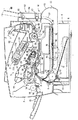
プロセスユニット22は、スキャナ部21の下方に配設され、本体ケーシング2に対して着脱自在に装着されている。このプロセスユニット22は、図2に示すように、プロセスユニット22の筐体を構成するドラムフレーム27内に、像担持体としての感光ドラム28と、現像カートリッジ29と、帯電器としてのスコロトロン型帯電器30と、転写手段としての転写ローラ31と、後で詳述するクリーニングユニット81とを備えている。
【0044】
現像カートリッジ29は、ドラムフレーム27に対して着脱自在に装着されており、トナーホッパ32と、そのトナーホッパ32の側方に設けられる供給ローラ33、現像手段としての現像ローラ34および層厚規制ブレード35とを備えている。
トナーホッパ32には、現像剤として、正帯電性の非磁性1成分のトナーが充填されている。このトナーとしては、スチレンなどのスチレン系単量体や、アクリル酸、アルキル(C1〜C4)アクリレート、アルキル(C1〜C4)メタアクリレートなどのアクリル系単量体に代表される重合性単量体を、懸濁重合などの公知の重合方法によって共重合させることにより得られる重合トナーが用いられている。重合トナーは、平均粒径は、約6〜10μm程度の略球形状をなし、流動性が極めて良好である。なお、重合トナーには、カーボンブラックなどの着色剤やワックスなどが配合される。さらに、トナーの流動性を向上させるために、シリカなどの外添剤が添加される。
【0045】
また、トナーホッパ32には、アジテータ36が設けられている。このアジテータ36は、トナーホッパ32内の中心に回転可能に支持される回転軸37と、その回転軸37の周りに設けられる攪拌羽根38と、その攪拌羽根38の遊端部に貼着されるフィルム39とを備えている。回転軸37が矢印方向へ回転すると、攪拌羽根38が周方向に移動して、フィルム39がトナーホッパ32内のトナーを掻き上げて、次に述べる供給ローラ33に向けて搬送する。
【0046】
回転軸37の攪拌羽根38が設けられた側と反対側には、トナーホッパ32の側壁に設けられるトナーの残量検知用の窓40を清掃するためのクリーナ41が設けられている。
供給ローラ33は、トナーホッパ32の側方において、アジテータ36の回転方向と逆方向に回転可能に設けられている。供給ローラ33は、金属製のローラ軸に、導電性のウレタンスポンジが被覆されて構成される。
【0047】
現像ローラ34は、供給ローラ33の側方において、供給ローラ33の回転方向と同方向に回転可能に設けられている。現像ローラ34は、金属製のローラ軸の表面に、導電性の弾性材料、カーボン微粒子を含む導電性のウレタンゴムまたはシリコーンゴムを被覆し、その弾性材料の表面に、フッ素が含有されているウレタンゴムまたはシリコーンゴムのコート層を被覆して形成される。また、現像ローラ34のローラ軸には、図示しない電源が接続され、所定の現像バイアスが印加されている。
【0048】
そして、これら供給ローラ33と現像ローラ34とは、互いに対向配置され、現像ローラ34に対して供給ローラ33がある程度圧縮するような状態で接触されており、供給ローラ33と現像ローラ34とは、それらの対向接触部分において、互いに逆方向に回転する。
層厚規制ブレード35は、供給ローラ33の上方であって、現像ローラ34の回転方向における供給ローラ33との対向位置と感光ドラム28との対向位置との間において、現像ローラ34の軸方向に沿って現像ローラ34と対向配置されている。この層厚規制ブレード35は、板ばね部材42と、その板ばね部材42の先端部に設けられ、現像ローラ34と接触される絶縁性のシリコーンゴムからなる圧接部43と、板ばね部材42の裏面に設けられるバックアップ部材44と、板ばね部材42の後端部を現像カートリッジ29に支持させるためのサポート部材45とを備えている。
【0049】
層厚規制ブレード35は、板ばね部材42がサポート部材45によって現像カートリッジ29に支持された状態で、圧接部43が板ばね部材42の弾性力によって、現像ローラ34の表面に圧接されている。
トナーホッパ32内のトナーは、アジテータ36の回転によって掻き上られ、供給ローラ33に向けて搬送される。なお、このアジテータ36の回転により、クリーナ41が回転され窓40が清掃される。
【0050】
供給ローラ33に搬送されてきたトナーは、その供給ローラ33の回転によって、現像ローラ34に供給される。この供給ローラ33から現像ローラ34へのトナーの供給時において、供給ローラ33と現像ローラ34との間においてトナーが摺擦され正極性に帯電される。
そして、帯電されたトナーは、現像ローラ34の表面上に担持され、現像ローラ34の回転に伴って、現像ローラ34と層厚規制ブレード35の圧接部43との間に進入する。トナーは現像ローラ34と圧接部43との間を通過するときに、さらに摩擦によって帯電され、その層の厚さが規制されて、現像ローラ34の表面上に薄層として担持される。
【0051】
感光ドラム28は、現像ローラ34の側方において、その現像ローラ34と対向配置され、現像ローラ34の回転方向と逆方向に回転可能となるようにドラムフレーム27に支持されている。この感光ドラム28は、円筒状のアルミニウム表面にポリカーボネートなどからなる正帯電性の感光層を形成したものであり、円筒状アルミニウムは電気的に接地されている。なお、この感光ドラム28の端部には、はす歯ギヤからなる感光ドラム駆動ギヤ28aが設けられている(図7参照)。
【0052】
スコロトロン型帯電器30は、感光ドラム28の上方において、感光ドラム28と接触しないように、所定の間隔を隔てて対向配置され、ドラムフレーム27に支持されている。このスコロトロン型帯電器30は、タングステン製の帯電用ワイヤからコロナ放電を発生させる正帯電用のスコロトロン型の帯電器であり、感光ドラム28の表面を一様に正極性に帯電させる。ワイヤと感光ドラム28との間には、グリッド電極30aが設けられる。
【0053】
感光ドラム28の回転に伴なって、感光ドラム28の表面は、スコロトロン型帯電器30により一様に正帯電され、所定の画像データに基づいてスキャナ部21から発光されたレーザビームが照射されることにより露光され、静電潜像が形成される。
次いで、現像ローラ34の回転により、現像ローラ34の表面上に担持されかつ正極性に帯電されているトナーが、感光ドラム28に対向して接触する時に、感光ドラム28の表面上に形成される静電潜像、すなわち、一様に正帯電されている感光ドラム28の表面のうち、レーザビームによって露光され電位が下がっている露光部分に供給され、選択的に担持されることによって可視像化される。
【0054】
転写ローラ31は、感光ドラム28の下方において、この感光ドラム28に対向配置され、ドラムフレーム27に感光ドラム28の回転方向と逆方向に回転可能に支持されている。この転写ローラ31は、金属製のローラ軸に、導電性のゴム材料が被覆されて形成され、ローラ軸には図示しない電源が接続される。トナーを用紙3へ転写する時には、所定の転写バイアスが印加される。
【0055】
そして、感光ドラム28の回転に伴い、レジストローラ10から搬送されてくる用紙3が感光ドラム28の表面と接触しながら、感光ドラム28と転写ローラ31との間を通る間に、感光ドラム28の表面に担持されたトナーが、用紙3に転写される。トナーが転写された用紙3は、図1に示すように、搬送ベルト46を介して、定着部23に向けて搬送される。
【0056】
定着部23は、プロセスユニット22の側方であって、用紙3の搬送方向下流側に設けられており、加熱ローラ47と、押圧ローラ48と、搬送ローラ49とを備えている。加熱ローラ47は、金属製の素管内にヒータとしてハロゲンランプを備えている。押圧ローラ48は、加熱ローラ47の下方に対向配置され、その加熱ローラ47を下方から押圧するように設けられている。また、搬送ローラ49は、加熱ローラ47および押圧ローラ48に対して、用紙3の搬送方向下流側に設けられている。
【0057】
用紙3に転写されたトナーは、加熱ローラ47と押圧ローラ48との間を通る間に、熱によって溶融し、用紙3に固着する。用紙3は、搬送ローラ49によって、本体ケーシング2に設けられる搬送ローラ50および排紙ローラ51に向けて搬送される。
搬送ローラ50は、搬送ローラ49に対して、用紙3の搬送方向下流側に設けられ、排紙ローラ51は、排紙トレイ52の上方に設けられる。搬送ローラ49によって搬送されてきた用紙3は、搬送ローラ50によって排紙ローラ51に搬送され、その後、排紙ローラ51によって、排紙トレイ52上に排出される。
【0058】
なお、このレーザプリンタ1では、転写ローラ31によって用紙3に転写された後に感光ドラム28の表面上に残存する残存トナーを現像ローラ34によって回収する、いわゆるクリーナレス現像方式によって残存トナーを回収している。このようなクリーナレス現像方式によって残存トナーを回収すれば、感光ドラム28から残存トナーを除去するためのブレードのような格別の部材および廃トナーの貯留部が不要となり、装置構成の簡略化を図ることができる。
【0059】
また、このレーザプリンタ1には、用紙3の両面に画像を形成するための再搬送ユニット61を備えている。この再搬送ユニット61は、反転機構部62と、再搬送トレイ63とが、一体的に構成され、本体ケーシング2における後部側に、反転機構部62が外付けされるとともに、再搬送トレイ63が給紙トレイ6の上方に挿入されるような状態で、着脱自在に装着されている。
【0060】
反転機構部62は、本体ケーシング2の後壁に外付けされ、略断面矩形状のケーシング64に、反転ローラ66および再搬送ローラ67を備えるとともに、上端部から、反転ガイドプレート68を上方に向かって突出させている。
なお、搬送ローラ49の下流側には、一方の面に画像が形成され搬送ローラ49によって搬送されてきた用紙3を、搬送ローラ50に向かう方向(実線の状態)と、後述する反転ローラ66に向かう方向(仮想線の状態)とに選択的に切り換えるためのフラッパ65が設けられている。
【0061】
このフラッパ65は、本体ケーシング2の後部において回動可能に支持されており、搬送ローラ49の下流側近傍に配置され、図示しないソレノイドの励磁または非励磁により、一方の面に画像が形成され搬送ローラ49によって搬送されてきた用紙3を、搬送ローラ50に向かう方向(実線の状態)と、後述する反転ローラ66に向かう方向(仮想線の状態)とに選択的に切り換えることができるように揺動可能に設けられている。
【0062】
反転ローラ66は、フラッパ65の下流側であって、ケーシング64の上部に配置され、1対のローラからなり、正方向および逆方向に回転の切り換えができるように構成されている。この反転ローラ66は、まず正方向に回転して、用紙3を反転ガイドプレート68に向けて搬送し、その後、逆方向に回転して、用紙3を反転方向に搬送できるように構成されている。
【0063】
再搬送ローラ67は、反転ローラ66の下流側であって、ケーシング64における反転ローラ66のほぼ真下に配置され、1対のローラからなり、反転ローラ66によって反転された用紙3を、再搬送トレイ63に搬送できるように構成されている。
また、反転ガイドプレート68は、ケーシング64の上端部から、さらに上方に向かって延びる板状部材からなり、反転ローラ66により送られる用紙3をガイドするように構成されている。
【0064】
そして、用紙3の両面に画像を形成する場合には、まず、フラッパ65が、用紙3を反転ローラ66に向かわせる方向に切り換えられ、反転機構部62に、一方の面に画像が形成された用紙3が受け入れられる。その後、その受け入れられた用紙3が反転ローラ66に送られてくると、反転ローラ66は、用紙3を挟んだ状態で正回転して、この用紙3を一旦反転ガイドプレート68に沿って、外側上方に向けて搬送する。用紙3の大部分が外側上方に送られ、用紙3の後端付近が反転ローラ66に挟まれた時に、反転ローラ66の正回転が停止する。
【0065】
次いで、反転ローラ66は逆回転して、用紙3を、前後逆向きの状態で、ほぼ真下に向かうようにして、再搬送ローラ67に搬送する。なお、反転ローラ66を正回転から逆回転させるタイミングは、定着部23の下流側に設けられる用紙通過センサ76が、用紙3の後端を検知した時から所定時間を経過した時となるように制御されている。また、フラッパ65は、用紙3の反転ローラ66への搬送が終了すると、元の状態、すなわち、搬送ローラ49から送られる用紙3を搬送ローラ50に送る状態に切り換えられる。
【0066】
次いで、再搬送ローラ67に搬送されてきた用紙3は、次に述べる再搬送トレイ63へ搬送される。
再搬送トレイ63は、用紙3が供給される用紙供給部69、トレイ本体70および斜行ローラ71を備えている。
用紙供給部69は、反転機構部62の下側において本体ケーシング2の後部に外付けされ、湾曲形状の用紙案内部材72を備えている。再搬送ローラ67からほぼ鉛直方向で送られてくる用紙3は、用紙案内部材72の湾曲形状によって、略水平方向に案内され、トレイ本体70に向けて略水平な状態で送り出される。
【0067】
トレイ本体70は、略矩形板状をなし、給紙トレイ6の上方において、略水平方向に設けられており、その上流側端部が、用紙案内部材72に連結されるとともに、その下流側端部が、トレイ本体70から搬送ローラ9に用紙3を案内するための再搬送経路73の上流側端部に連結されている。再搬送経路73の下流側端部は、搬送ローラ9に向けて延びている。
【0068】
また、トレイ本体70における用紙3の搬送路には、用紙3を、図示しない基準板に当接させながら搬送するための斜行ローラ71が、用紙3の搬送方向において所定の間隔を隔てて2つ配置されている。
各斜行ローラ71は、トレイ本体70の幅方向一端部に設けられる図示しない基準板の近傍に配置され、その軸線が用紙3の搬送方向と略直交する方向に配置される斜行駆動ローラ74と、その斜行駆動ローラ74と用紙3を挟んで対向し、その軸線が、用紙3の搬送方向と略直交する方向から、用紙3の送り方向が基準面に向かう方向に傾斜する方向に配置される斜行従動ローラ75とを備えている。
【0069】
用紙供給部69からトレイ本体70に送り出された用紙3は、斜行ローラ71によって、その用紙3の幅方向一端縁が基準板に当接されながら、再搬送経路73を介して、搬送ローラ9へ送られる。表裏が反転された状態の用紙3は、レジストローラ10を経て画像形成位置に向けて搬送される。そして、再び、画像形成位置に搬送された用紙3の裏面が、感光ドラム28と対向接触され、可視像を形成するトナーが転写された後、定着部23において定着され、両面に画像が形成された状態で、排紙トレイ52上に排紙される。
【0070】
レーザプリンタ1のプロセスユニット22には、転写後に感光ドラム28の表面上に残存する残存トナーを一時的に捕捉しつつ、転写時に用紙3から感光ドラム28の表面上に付着する異物としての紙粉を回収するためのクリーニングユニット81が設けられている。
クリーニングユニット81は、図2に示すように、ドラムフレーム27内において、感光ドラム27に対して現像ローラ34の反対側に設けられており、1次ローラとしての1次クリーニングローラ82と、2次ローラとしての2次クリーニングローラ83と、これら1次クリーニングローラ82および2次クリーニングローラ83を支持するホルダ部材84とを備えている。
【0071】
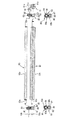
1次クリーニングローラ82は、図3に示すように、引き抜き法で作製された鉄材にニッケルメッキを析出させた軸体からなるローラ軸82aと、発泡シリコーンゴム、発泡ウレタンゴム、発泡EPDMなど導電性の発泡体からなるローラ部82bとを備えている。ローラ部82bは、ローラ軸82aの軸方向両端部が露出するように、ローラ軸82aの軸方向にわたってローラ軸82aの周りに設けられている。
【0072】
また、2次クリーニングローラ83は、引き抜き法で作製された鉄材にニッケルメッキを析出させた軸体からなり、その両端部のローラ軸83aと、内側部のローラ軸83aより大径のローラ部83bとが一体として形成される。また、ローラ部83bの表面粗さは、Rz(10点平均表面粗さ)が3.2μm以下とされている。
【0073】
2次クリーニングローラ83のローラ部83bにおける直径は、1次クリーニングローラ82のローラ部82bの直径よりも、小径に形成されており、また、2次クリーニングローラ83のローラ部83bの軸方向長さが、1次クリーニングローラ82のローラ部82bの軸方向長さと、同じか、それよりも長く形成されている。
【0074】
1次クリーニングローラ82と、2次クリーニングローラ83とを、上述のように構成すれば、1次クリーニングローラ82によって、感光ドラム28上の紙粉を良好に捕捉し、次いで、1次クリーニングローラ82上の紙粉を2次クリーニングローラ83に良好に捕捉することができ、紙粉の良好な捕捉を実現することができる。
【0075】
なお、1次クリーニングローラ82のローラ部82bの軸方向長さは、感光ドラム28の軸方向における画像形成領域の長さと、同じか、それよりも長く形成されている。そのため、この1次クリーニングローラ82によって、感光ドラム28の画像形成領域全体にわたって、良好な紙粉の除去を達成することができる。
【0076】
そして、これら1次クリーニングローラ82および2次クリーニングローラ83は、それらの軸方向両端部において、共通の軸受部材85によって回転可能に支持されている。
すなわち、軸受部材85は、樹脂からなり、略楕円板状の軸受板86と、その軸受板86に一体的に形成される1次軸受部87および2次軸受部88とを備えている。1次軸受部87および2次軸受部88は、それぞれ、軸受板86を直交方向に貫通する筒状をなし、1次クリーニングローラ82のローラ軸82aおよび2次クリーニングローラ83のローラ軸83aを挿通支持できるように互いに隣り合って形成されている。
【0077】
また、各軸受部材85には、図3に示すように、第1シール部材としてのサイドフィルム89と、付勢部材としてのねじりばね90とが設けられている。サイドフィルム89は、ポリエチレンテレフタレートなどの可撓性の樹脂フィルムからなり、軸受板86と略同一の楕円形状をなし、1次軸受部87および2次軸受部88がそれぞれ挿通される2つの孔が形成されている。また、ねじりばね90は、鋼線からなり、鋼線が巻回されるコイル部90aと、そのコイル部90の両端から、同方向に向かって、互いに略ハ字状となるように直線状に延びる端部90bおよび90cとが一体的に形成されている。
【0078】
そして、ねじりばね90のコイル部90aは、軸受板86に対して軸方向(単に軸方向という場合には、1次クリーニングローラ82、2次クリーニングローラ83および感光ドラム28の軸方向に沿う方向であって、後述するホルダ部材84、紙粉貯留部94、アッパフレーム110、ロアフレーム111などの幅方向と同方向を意味する。以下同様)内側から2次軸受部88に外嵌される。かつ、ねじりばね90の一方側の端部90bは1次軸受部87に下向きに係止される。また、サイドフィルム89は、ねじりばね90が取り付けられた状態の軸受部材85において、2つの孔が1次軸受部87および2次軸受部88に対して、軸受板86に対して軸方向内側から外嵌されるように取り付けられている。
【0079】
1次クリーニングローラ82のローラ軸82aの軸方向両端部は各1次軸受部87にそれぞれ挿通され、また、2次クリーニングローラ83のローラ軸83aの軸方向両端部は各2次軸受部88にそれぞれ挿通される。このようにして、1次クリーニングローラ82のローラ軸82aの軸方向両端部および2次クリーニングローラ83のローラ軸83aの軸方向両端部に軸受部材85が取り付けられる。
【0080】
これによって、図4に示すように、1次クリーニングローラ82および2次クリーニングローラ83は、互いに接触するように、平行配置された状態で、共通の軸受部材85によって回転可能に軸受支持される。
また、1次クリーニングローラ82のローラ軸82aの軸方向両端部および2次クリーニングローラ83のローラ軸83aの軸方向両端部に各軸受部材85が取り付けられた状態において、1次クリーニングローラ82のローラ軸82aの一方側軸端部、および、2次クリーニングローラ83のローラ軸83aの一方側軸端部には、カラー部材としてのカラー93aおよび93bが、それぞれ設けられている。これらカラー93aおよび93bは、略円筒形状をなし、導電性の樹脂から形成されている。
【0081】
また、1次クリーニングローラ82のローラ軸82aの軸方向両端部および2次クリーニングローラ83のローラ軸83aの軸方向両端部に各軸受部材85が取り付けられた状態において、1次クリーニングローラ82のローラ軸82aの他方側軸端部には、1次クリーニングローラ駆動ギヤ91が、2次クリーニングローラ83のローラ軸83aの他方側軸端部には、2次クリーニングローラ駆動ギヤ92が、それぞれ設けられている。
【0082】
1次クリーニングローラ駆動ギヤ91は、感光ドラム駆動ギヤ28aと噛み合うはす歯ギヤ91aと、2次クリーニングローラ駆動ギヤ92と噛み合う平歯ギヤ91bとから一体的に形成されている。はす歯ギヤ91aと平歯ギヤ91bとは、はす歯ギヤ91aのほうが平歯ギヤ91bに対して、1次クリーニングローラ82の軸方向外側となるように形成される。また、はす歯ギヤ91aの軸方向外側端面には、軸方向外側に略半球状に突出する突部91cが形成されている。
【0083】
また、2次クリーニングローラ駆動ギヤ92は、1次クリーニングローラ駆動ギヤ91の平歯ギヤ91bと噛み合う平歯ギヤである。
そして、1次クリーニングローラ駆動ギヤ91および2次クリーニングローラ駆動ギヤ92は、1次クリーニングローラ駆動ギヤ91の平歯ギヤ91bと2次クリーニングローラ駆動ギヤ92とが噛み合う状態で、1次クリーニングローラ82のローラ軸82aの他方側軸端部と、2次クリーニングローラ83のローラ軸83aの他方側軸端部とに、それぞれ取り付けられている。
【0084】
これによって、1次クリーニングローラ82と、2次クリーニングローラ83とは、1次クリーニングローラ駆動ギヤ91の平歯ギヤ91bと2次クリーニングローラ駆動ギヤ92との噛み合いによって連結される。なお、1次クリーニングローラ82と、2次クリーニングローラ83とは、1次クリーニングローラ駆動ギヤ91の平歯ギヤ91bと2次クリーニングローラ駆動ギヤ92との噛み合いによって、実質的に1:1の周速比で駆動されるように設定されている。
【0085】
そして、1次クリーニングローラ82および2次クリーニングローラ83は、それらの軸方向両端部において共通の軸受部材85によって回転可能に軸受支持された状態で、図5に示すように、ホルダ部材84に装着されている。
ホルダ部材84は、樹脂からなり、異物貯留部としての紙粉貯留部94とローラ受け部95とを一体的に備えている。
【0086】
紙粉貯留部94は、図5および図6に示すように、その幅方向に沿って延びる平面視略矩形状かつ側断面視凹状をなし、その幅方向に沿って複数の突出壁96が、互いに所定の間隔を隔てて設けられている。この突出壁96は、紙粉貯留部94を幅方向において所定の空間毎に仕切るように、幅方向と直交する方向に沿って底壁97から立設されている。また、この突出壁96の上端部は、後述するように、アッパフレーム110とロアフレーム111とが組み付けられた状態で、紙粉貯留部94の上方の空間が幅方向において連通されるように、後述するアッパフレーム110の天井部130と所定の間隔が隔てられる高さとして形成されている。
【0087】
また、ホルダ部材84における紙粉貯留部94の幅方向両側端部には、ホルダ側リブとしてのホルダ側画成リブ98と、そのホルダ側画成リブ98の幅方向外側に、ばね受け部99とが、それぞれ設けられている。
ホルダ側画成リブ98は、紙粉貯留部94の両側端部において、幅方向と直交する方向に沿って上方に向かって立設されており、その上端部が、図5(b)および図5(c)に示すように、後述するアッパフレーム110の天井部130(図13参照)に沿う傾斜状に形成されている。なお、このホルダ側画成リブ98は、後述するように、アッパフレーム110とロアフレーム111とが組み付けられた状態で、その上端部が、後述するスポンジシール133と接触し、かつ、アッパフレーム110の天井部130と所定の間隔が隔てられる高さとして形成されている(図13参照)。
【0088】
また、ばね受け部99は、板状をなし、ホルダ側画成リブ96の幅方向外側に、ホルダ側画成リブ96と幅方向において所定の間隔を隔てて設けられており、1次クリーニングローラ82および2次クリーニングローラ83がホルダ部材84に支持された状態において、ねじりばね90の他方側の端部90cと対向するように幅方向に沿って形成されている。
【0089】
また、紙粉貯留部94の前端部(プロセスユニット22における現像カートリッジ29側を後側、クリーニングユニット81側を前側とする。以下同様)には、後述するスポンジシール133と接触する前壁101が、幅方向に沿って、上方に向かって底壁97から屈曲形成されている。
【0090】
また、ローラ受け部95は、紙粉貯留部94の後側において、紙粉貯留部94と一体的に形成されており、幅方向に沿って形成される底壁100と、幅方向両端部に設けられ、各軸受部材85をそれぞれ受ける軸受支持部102とを備えている。
ローラ受け部95の底壁100は、図6(b)に示すように、凹状をなし、紙粉貯留部94の底壁97から連続して形成されている。なお、ローラ受け部95の底壁100と紙粉貯留部94の底壁97との間には、幅方向に沿って断面逆凹状に突出する突溝部103が形成されている。
【0091】
また、この突溝部103には、下方後側から上方前側に向かって傾斜する傾斜面が形成されるシール貼着部104が幅方向に沿って突出形成されており、このシール貼着部104の傾斜面に、幅方向にわたって、第2シール部材としてのミッドフィルム105が貼着されている。このミッドフィルム105は、略矩形状をなし、ポリエチレンテレフタレートなどの可撓性の樹脂フィルムからなり、シール貼着部104の傾斜面に沿って、その遊端部が前側に向かうように傾斜状に設けられている。
【0092】
また、ローラ受け部95における底壁101の後端部には、その後端部から上方に向かって屈曲した後壁106が形成される。後壁106には、下方前側から上方後側に向かって傾斜する傾斜面が形成されている。この後壁106の傾斜面には、幅方向にわたって、第4シール部材としてのロアフィルム107が貼着されている。このロアフィルム107は、略矩形状をなし、ポリエチレンテレフタレートなどの可撓性の樹脂フィルムからなり、後壁106の傾斜面の傾斜面に沿って、その遊端部が後側に向かうように傾斜状に設けられている。
【0093】
なお、図6(a)に示すように、ミッドフィルム105およびロアフィルム107の長手方向長さは、1次クリーニングローラ82の軸方向長さと同じか、それよりも長く形成されている。
また、各軸受支持部102は、板状をなし、図5(b)に示すように、軸受部材85の1次軸受部87を受ける1次側凹部108と、2次軸受部88を受ける2次側凹部109とが形成されている。
【0094】
そして、各軸受部材85は、ホルダ部材84のローラ受け部95に装着されることにより、ホルダ部材84に対して支持される。
すなわち、ねじりばね90がばね受け部99に係止された状態(図5(b)および(c)参照)で、1次軸受部87および2次軸受部88の軸受板86に対して軸方向内側へ突出する部分が、各軸受支持部102の1次側凹部108および2次側凹部109にそれぞれ遊嵌状態で嵌め込まれている。このようにして、2次軸受部88がねじりばね90によって下方に向けて付勢され、各軸受部材85がホルダ部材84に装着される。
【0095】
なお、各軸受部材85の1次軸受部87および2次軸受部88が、各軸受支持部102の1次側凹部108および2次側凹部109にそれぞれ遊嵌状態で嵌め込まれている状態において、1次クリーニングローラ82および2次クリーニングローラ83は、前後方向に一体的に移動可能とされ、常には、ねじりばね90によって、2次クリーニングローラ83が下方に向かって付勢され、かつ、1次クリーニングローラ82が後方に向かって付勢されている。
【0096】
また、1次クリーニングローラ82および2次クリーニングローラ83がホルダ部材84によって支持された状態においては、図13に示すように、ミッドフィルム105が2次クリーニングローラ83と下方から対向する。ミッドフィルム105は、ミッドフィルム105の遊端部の端縁が2次クリーニングローラ83の回転方向下流側方向へ向かうような状態で、2次クリーニングローラ83の軸方向にわたって接触する。これによって、後述するように、アッパフレーム110とロアフレーム111とが組み付けられた状態において、2次クリーニングローラ83の下側において、紙粉貯留部94と1次クリーニングローラ82とが、ミッドフィルム105によって画成される。
【0097】
そして、図7に示すように、1次クリーニングローラ82および2次クリーニングローラ83を支持しているホルダ部材84が、クリーニングユニット81として一体化された状態で、ドラムフレーム27に装着される。
ドラムフレーム27は、図13に示すように、上側筐体としてのアッパフレーム110と、下側筐体としてのロアフレーム111とに分割可能に構成されている。ホルダ部材84がロアフレーム111に組み付けられた状態で、アッパフレーム110とロアフレーム111とが組み合わされることにより、クリーニングユニット81は、アッパフレーム110とロアフレーム111との間で挟まれる。
【0098】
ロアフレーム111は、樹脂からなり、図7ないし図10に示すように、前後方向において、ホルダ部材84が装着されるホルダ装着部112と、感光ドラム28および転写ローラ31が装着されるドラム装着部113と、現像カートリッジ29が装着されるカートリッジ装着部114とが、連続して一体的に形成されている。
【0099】
ホルダ装着部112は、ロアフレーム111の前端部に設けられており、図13にも示すように、その幅方向に沿って形成される突条部115と、その両端部において前後方向に沿って形成される当接部材としての下側支持リブ116とが設けられている。
突条部115は、ホルダ部材84が組み付けられた状態で、ホルダ部材84の突溝部103に嵌合するように上方に向かって突出形成されている。
【0100】
また、各下側支持リブ116は、ホルダ装着部112の幅方向両端部において、1次軸受部87および2次軸受部88の軸受板86に対して軸方向外側へ突出する部分と対向するように上方に向かって立設されている。各下側支持リブ116は、図15および図16に示すように、1次軸受部87の下側と対向する1次側底面117および1次軸受部87の前側側方と対向する1次側前側面118を備える略L字状の1次側受部119と、2次軸受部88の下側と対向する2次側底面120および2次軸受部88の前側側方と対向する2次側前側面121を備える略L字状の2次側受部122とが、上下方向において2段の階段状に形成されている。
【0101】
より具体的には、各下側支持リブ116のうち、1次クリーニングローラ82の軸方向両端部において、後述する電極板128aおよび128bと対向する幅方向一方側(以下、電極側とする。)端部に配置される下側支持リブ116の1次側底面117は、アッパフレーム110とロアフレーム111とが組み付けられた状態において、図16に示すように、1次軸受部87を下から押圧するような高さとして設定されている。また、後述する摺動板129と対向する幅方向他方側(以下、ギヤ側とする。)端部に配置される下側支持リブ116の1次側底面117は、アッパフレーム110とロアフレーム111とが組み付けられた状態において、図15に示すように、1次軸受部87を下から押圧しない高さとして設定されている。
【0102】
また、各下側支持リブ116の1次側前側面118は、アッパフレーム110とロアフレーム111とが組み付けられた状態において、1次クリーニングローラ82を感光ドラム28に対して位置決めするように設定されている。
また、ホルダ装着部112の突条部115の後側には、ホルダ部材84のローラ受け部95を受けるホルダ受けリブ123が、幅方向に沿って互いに所定の間隔を隔てて、前後方向に沿って複数立設されている。
【0103】
また、ホルダ装着部112の電極側端部には、図7および図8に示すように、給電部材としての2つの電極板128aおよび128bがそれぞれ設けられている。各電極板128aおよび128bは、電極側に形成される下側支持リブ116よりも幅方向外側において、先に述べたカラー93aおよび93bの外周面と対向接触するように設けられている。
【0104】
また、ホルダ装着部112のギヤ側端部には、図7に示すように、1次クリーニングローラ駆動ギヤ91の突部91cと対向配置される金属板からなる摺動板129が設けられている。
ドラム装着部113は、ホルダ装着部112の後側に設けられており、図10に示すように、下部において、転写ローラ31が回転自在に支持される転写ローラ支持部124と、図7に示すように、上部において、感光ドラム28が回転自在に支持される感光ドラム支持部125とを備えている。
【0105】
カートリッジ装着部114は、現像カートリッジ29を受ける平面視略矩形板状の受板部126と、その受板部126の幅方向両側から上方に向けて屈曲形成される側板部127とを備えている。
アッパフレーム110は、樹脂からなり、図11および図12に示すように、底面視略矩形状をなし、前後方向において、クリーニングユニット81を覆う天井部130と、スコロトロン型帯電器30が支持される帯電器支持部131と、スキャナ部21からのレーザビームを感光ドラム28に照射させるためのレーザビーム通過部132とが、連続して一体的に形成されている。
【0106】
天井部130は、アッパフレーム110の前端部に設けられており、図13にも示すように、その幅方向に沿って形成される第3シール部材としてのスポンジシール133および掻取部材としてのスポンジスクレーパ134と、その両端部において前後方向に沿って形成される天井側画成リブ135および上側支持リブ136とが設けられている。
【0107】
スポンジシール133は、略矩形板状をなし、紙粉貯留部94の底壁97と上下方向において対向するように、天井部130の前端部に、幅方向にわたって支持されている。
スポンジスクレーパ134は、平面視略矩形状をなし、スポンジシール133の後側において、スポンジシール133と所定の間隔を隔てて平行配置され、天井部130に突出形成される横リブ137に、幅方向にわたって支持されている。このスポンジスクレーパ134は、このスポンジスクレーパ134の2次クリーニングローラ83に対する摩擦係数が、1次クリーニングローラ82の2次クリーニングローラ83に対する摩擦係数よりも小さくなるように、ウレタンスポンジから形成されている。また、このスポンジスクレーパ134は、後述するように、スポンジスクレーパ134における2次クリーニングローラ83が接触する接触部分から2次クリーニングローラ83の回転方向の下流側方向に向かって傾倒しにくい形状に形成されている。より具体的には、図17(a)に示すように、スポンジスクレーパ134における2次クリーニングローラ83との接触部分Cの接線方向の長さ(つまり、前後方向長さ)Aが、接線方向に直交する直交方向の長さ(つまり、上下方向長さ(厚さ))Bよりも長く形成されている。
【0108】
各天井側画成リブ135は、スポンジシール133およびスポンジスクレーパ134の幅方向両端部において、ホルダ側画成リブ98およびばね受け部99の間と対向配置されるように、前後方向に沿って下方に向かって立設されている。
また、各上側支持リブ136は、各天井側画成リブ135よりも幅方向外側において、各天井側画成リブ135と所定の間隔を隔てて平行配置され、前後方向に沿って下方に向かって立設されている。各上側支持リブ136は、1次軸受部87および2次軸受部88の軸受板86に対して軸方向外側へ突出する部分を挟んで、各下側支持リブ116と対向するように形成されている。
【0109】
各上側支持リブ136は、図15および図16に示すように、1次軸受部87の上側と対向する1次側上面138を備える1次側保持部139と、2次軸受部88の上側と対向する2次側上面140および2次軸受部88の後側側方と対向する2次側後側面141を備える略L字状の2次側保持部142とが、上下方向において1段の段状に形成されている。
【0110】
より具体的には、1次クリーニングローラ82の軸方向両端部において、電極側端部に形成される上側支持リブ136の1次側上面138は、アッパフレーム110とロアフレーム111とが組み付けられた状態において、図16に示すように、1次軸受部87を上から押圧しない高さとして設定されている。また、ギヤ側端部に形成される上側支持リブ136の1次側上面138は、アッパフレーム110とロアフレーム111とが組み付けられた状態において、図15に示すように、1次軸受部87を上から押圧できるような高さとして設定されている。
【0111】
帯電器支持部131は、天井部130の後側に設けられており、図12に示すように、前後方向に互いに所定の間隔を隔てて対向配置される前側支持リブ143および後側支持リブ144が、幅方向に沿って下方に向かって立設されている。そして、これら前側支持リブ143および後側支持リブ144の間に、スコロトロン型帯電器30が、幅方向に沿って設けられている。
【0112】
グリッド電極30aは、前側支持リブ143および後側支持リブ144の間に、前後方向に互いに所定の間隔を隔てて、幅方向に沿って複数本設けられている。
また、前側支持リブ143における下端部の前側面には、幅方向にわたって、第5シール部材としてのアッパフィルム145が貼着されている。このアッパフィルム105は、略矩形状をなし、ポリエチレンテレフタレートなどの可撓性の樹脂フィルムからなり、前側支持リブ143の前側面に沿って、その遊端部が下側に向かうように設けられている。
【0113】
レーザビーム通過部132は、帯電器支持部131の後側に設けられており、スキャナ部21からのレーザビームを感光ドラム28に照射させるためのレーザビーム通路146が、前側下方に傾斜状に開口形成されている。
そして、ホルダ部材84は、図13に示すように、ホルダ部材84の突溝部103に突条部115が嵌合されることにより、ロアフレーム111のホルダ装着部112に組み付けられ、ホルダ部材84がロアフレーム111に対して位置決めされる。
【0114】
このように組み付けることによって、図2に示すように、1次クリーニングローラ82は、感光ドラム28の回転方向に対して、転写ローラ31との対向位置の下流側であって、かつ、スコロトロン型帯電器30との対向位置の上流側となる位置に、感光ドラム28と対向配置される。また、2次クリーニングローラ83は、その1次クリーニングローラ82に対して感光ドラム28と反対側に配置され、さらに、紙粉貯留部94は、その2次クリーニングローラ83に対して、1次クリーニングローラ82と反対側に配置される。
【0115】
また、図15および図16に示すように、ロアフレーム111の各下側支持リブ116が、1次軸受部87および2次軸受部88の軸受板86に対して軸方向外側へ突出する部分と下側から対向する。1次軸受部87の下側および前側側方が、1次側底面117および1次側前側面118とそれぞれ対向することによって、1次軸受部87が1次側受部119に受けられる。また、2次軸受部88の下側および前側側方が、2次側底面120および2次側前側面121と対向することによって、2次軸受部88が2次側受部122に受けられる。
【0116】
また、図13に示すように、ロアフィルム107は感光ドラム28と側方において対向する。ロアフィルム107は、ロアフィルム107の遊端部の端縁が、感光ドラム28の回転方向下流側方向へ向かうような状態で、感光ドラム28の軸方向にわたって接触する。
また、図8に示すように、各電極板128aおよび128bが、1次クリーニングローラ82のローラ軸82aの一方側軸端部、および、2次クリーニングローラ83のローラ軸83aの一方側軸端部にそれぞれ設けられる各カラー93aおよび93bの外周面と、各カラー93aおよび93bの下側から上下方向において摺動可能に接触される。
【0117】
また、図7に示すように、感光ドラム駆動ギヤ28aとはす歯ギヤ91aとが噛み合うことによって、感光ドラム28と1次クリーニングローラ82とが連結され、実質的に1:2の周速比で駆動されるように設定されている。また、摺動板129は、1次クリーニングローラ駆動ギヤ91の突部91cと対向配置される。
【0118】
ホルダ部材84がロアフレーム111に組み付けられた状態で、アッパフレーム110がロアフレーム111に組み付けられると、図15および図16に示すように、1次軸受部87は、1次側底面117および1次側前側面118からなる1次側受部119と、1次側上面138からなる1次側保持部139とによって挟持状に保持される。
【0119】
また、2次軸受部88は、2次側底面120および2次側前側面121からなる2次側受部122と、2次側上面140および2次側後側面141からなる2次側保持部142とによって挟持状に保持される。
このようにして、各軸受部材85は、アッパフレーム110の上側支持リブ136と、ロアフレーム111の下側支持リブ116とで上下方向から挟まれることにより、位置決めされる。
【0120】
より具体的には、1次クリーニングローラ82は、図16に示すように、その一方側端部において、1次軸受部87が1次側底面117によって下から押圧され、図15に示すように、他方側端部において、1次軸受部87が1次側上面138によって上から押圧されることによって、水平方向が位置決めされる。さらに、両端部において、各1次軸受部87が各1次側前側面118に当接されることによって、前後方向において、感光ドラム28に対して位置決めされる。そして、1次クリーニングローラ82は、このように位置決めされた状態で、常には、ねじりばね90によって、感光ドラム28に向かって付勢されている。
【0121】
また、2次クリーニングローラ83は、各2次軸受部88が、各2次側受部122に受けられた状態で、各2次側受部122と2次側保持部142との間で遊嵌状態で保持される。
また、ホルダ部材84がロアフレーム111に装着された状態で、アッパフレーム110がロアフレーム111に組み合わされると、図7に示す、各ホルダ側画成リブ98と各ばね受け部99との間に、図10に示す、各天井側画成リブ135が受け入れられる。これによって、図14に示すように、紙粉貯留部94の両端部において、これら各ホルダ側画成リブ98と各天井側画成リブ135とが幅方向において互いに重なり合うことにより、オーバーラップ部147が形成される。このオーバーラップ部147によって、紙粉貯留部94の両端部が画成される。
【0122】
さらに、図13に示すように、ホルダ部材84がロアフレーム111に装着された状態で、アッパフレーム110がロアフレーム111に組み合わされると、各ホルダ側画成リブ98の上端部と、前壁101の上端部とが、アッパフレーム110の天井部130に支持されているスポンジシール133に接触し、また、アッパフレーム110の天井部130に支持されるスポンジスクレーパ134の下部が、2次クリーニングローラ83と、その軸方向にわたって接触する。
【0123】
これによって、紙粉貯留部94は、その幅方向両端部が、各ホルダ側画成リブ98、各天井側画成リブ135およびスポンジシール133によってシールされた状態で画成され、また、その前端部が、前壁101およびスポンジシール133によってシールされた状態で画成され、その後端部が、スポンジスクレーパ134、2次クリーニングローラ83およびミッドフィルム105によってシールされた状態で画成される。その結果、紙粉貯留部94を含む空間が、紙粉貯留室148として形成され、次に述べるローラ室149から画成される。
【0124】
また、図13に示すように、アッパフィルム145が、1次クリーニングローラ82とスコロトロン型帯電器30との間において、感光ドラム28と上方から対向するように配置される。アッパフィルム145の遊端部の端縁は、感光ドラム28の軸方向にわたって、感光ドラム28と接触しないようなわずかな隙間を隔てた状態に保持される。これによって、1次クリーニングローラ82は、1次クリーニングローラ82と感光ドラム28との間の下側において、ロアフィルム107によって感光ドラム28から画成され、また、その上側において、アッパフィルム145によって感光ドラム28およびスコロトロン型帯電器30から画成される。
【0125】
これによって、1次クリーニングローラ82および2次クリーニングローラ83を収容する空間が、スポンジスクレーパ134、ミッドフィルム105、ロアフィルム107およびアッパフィルム145によって、ローラ室149として形成され、紙粉貯留室148および感光ドラム28から、それぞれ画成される。
図示しないモータからの動力によって感光ドラム28が回転されると、その動力が、感光ドラム駆動ギヤ28aおよび1次クリーニングローラ駆動ギヤ91のはす歯ギヤ91aを介して、1次クリーニングローラ82に伝達され、さらに、1次クリーニングローラ駆動ギヤ91の平歯ギヤ91bおよび2次クリーニングローラ駆動ギヤ92を介して、2次クリーニングローラ83に伝達される。よって、感光ドラム28とともに、1次クリーニングローラ82および2次クリーニングローラ83が、それぞれ図13に示す矢印方向(1次クリーニングローラ82が時計方向、2次クリーニングローラ83が反時計方向)に回転する。
【0126】
そして、トナーを、用紙3へ転写する時には、感光ドラム28上のトナーを1次クリーニングローラ82へ吸引するために、感光ドラム28の表面電位よりも低いバイアス(負極性のバイアス)が、電極板128aおよびカラー93aを介して、1次クリーニングローラ82に印加される。すると、感光ドラム28に残存するトナーが、1次クリーニングローラ82に一時的に捕捉される。
【0127】
一方、トナーが用紙3へ転写されない時、つまり、連続して送られる用紙3と用紙3の間隔に相当する間には、感光ドラム28上の紙粉を1次クリーニングローラ82へ吸引するために、感光ドラム28の表面電位よりも高いバイアス(正極性のバイアス)が、電極板128aおよびカラー93aを介して、1次クリーニングローラ82に印加される。すると、1次クリーニングローラ82に一時的に捕捉されているトナーは感光ドラム28に戻され、転写時に用紙3から感光ドラム28に付着した紙粉が、1次クリーニングローラ82に捕捉される。感光ドラム28に戻されたトナーは、現像ローラ34によって回収される。
【0128】
そのため、転写後に、感光ドラム28の表面に残存トナーが多量に残存しても、残存トナーを確実に現像ローラ34において回収することができる。よって、感光ドラム28に残存するトナーによる画質への悪影響を防止できる。
また、1次クリーニングローラ82上の紙粉のみを2次クリーニングローラ83に吸引するために、2次クリーニングローラ83には、電極板128bおよび導電性のカラー93bを介して、1次クリーニングローラ82の表面電位よりも高いバイアス(正極性のバイアス)が、常に印加されている。
【0129】
1次クリーニングローラ82に捕捉された紙粉は、2次クリーニングローラ83と対向した時に、常に2次クリーニングローラ83へ電気的に捕捉される。2次クリーニングローラ83に捕捉された紙粉は、スポンジスクレーパ134と対向した時に、そのスポンジスクレーパ134によって掻き取られ、紙粉貯留部94に溜められる。
【0130】
すなわち、このクリーニングユニット81では、1次クリーニングローラ82によって、感光ドラム28上の残存トナーおよび紙粉が電気的に吸引される。1次クリーニングローラ82に吸引されたトナーは感光ドラム28上へ電気的に戻される一方、1次クリーニングローラ82に吸引された紙粉は2次クリーニングローラ83によって電気的に吸引され、2次クリーニングローラ83に捕捉される。そのため、クリーナレス現像方式によって残存トナーの回収と並行して効率的に紙粉を除去することができ、紙粉除去性能の向上を図ることができる。
【0131】
しかも、2次ローラによって捕捉された紙粉が、スポンジスクレーパ134によって掻き取られた後、紙粉貯留部94において貯留されるので、除去された紙粉を飛散させることなく、溜めることができる。そのため、一旦除去した紙粉が、再び感光ドラム28に付着することを防止でき、紙粉除去性能の向上を図ることができる。また、スポンジスクレーパ134によって2次クリーニングローラ83に吸引された紙粉を掻き取るので、2次クリーニングローラ83の紙粉の捕捉性能を長期にわたって維持することができ、紙粉除去性能を保つことができる。
【0132】
また、紙粉貯留部94の底壁97からは、複数の突出壁96が幅方向において互いに所定の間隔を隔てて立設されている。これら突出壁96により、紙粉貯留部94が幅方向に沿って上方の空間が連通された状態で画成されるので、プロセスユニット22を傾けても、各突出壁96によって画成された空間毎に紙粉を保持することができる。そのため、紙粉貯留部94における紙粉の幅方向における移動を防止して、紙粉貯留部94から紙粉が漏れることを低減することができる。
【0133】
また、このプロセスユニット22では、1次クリーニングローラ82および2次クリーニングローラ83の軸方向両端部が、共通の軸受部材85によってそれぞれ軸受支持されているので、1次クリーニングローラ82と2次クリーニングローラ83との相対配置を確実に一定に保つことができる。そのため、これら1次クリーニングローラ82および2次クリーニングローラ83の圧接力が安定し、安定した駆動による紙粉除去性能の向上を図ることができる。
【0134】
また、このプロセスユニット22では、アッパフレーム110とロアフレーム111とを組み合わせて、各軸受部材85を挟むのみで、各軸受部材85、ひいては、1次クリーニングローラ82および2次クリーニングローラ83を位置決めすることができる。そのため、簡易な組み付けによって、1次クリーニングローラ82および2次クリーニングローラ83を、それらの相対位置を保ちながら、確実に位置決めすることができる。
【0135】
しかも、このプロセスユニット22では、1次クリーニングローラ82は、その軸方向両端部において、ギヤ側端部が1次軸受部87を介して、アッパフレーム110の上側支持リブ136の1次側上面138によって上から押さえられ、電極側端部が1次軸受部87を介して、ロアフレーム111の下側支持リブ116の1次側底面117によって下から押さえられるので水平方向においてバランスよく位置決めされる。そのため、感光ドラム28に対して、1次クリーニングローラ82を、軸方向において均一に接触させることができ、安定した駆動を確保することができる。
【0136】
すなわち、このように位置決めされた状態において、感光ドラム28を駆動させると、感光ドラム駆動ギヤ28aとはす歯ギヤ91aとの噛み合いによって、1次クリーニングローラ82が、回転駆動される。このプロセスユニット22では、感光ドラム駆動ギヤ28aとはす歯ギヤ91aとは、その噛み合い部分において、ともに下から上に向かって回転されるので、感光ドラム駆動ギヤ28aがはす歯ギヤ91aを、上方に押し上げようとする。その結果、1次クリーニングローラ82のギヤ側端部には、上方に押し上げられる力が働く。
【0137】
しかし、1次クリーニングローラ82の軸方向両端部において、電極側端部では、1次軸受部87が1次側底面117によって下から押圧され、また、ギヤ側端部では、1次軸受部87が1次側上面138によって上から押圧される。よって、1次クリーニングローラ82のギヤ側端部が、感光ドラム駆動ギヤ28aとはす歯ギヤ91aの噛み合いによって発生する力によって上方に押し上げられることを確実に防止し、1次クリーニングローラ82は、軸方向において感光ドラム28に均一に接触するので、感光ドラム28および1次クリーニングローラ82を安定して駆動させることができる。
【0138】
また、このプロセスユニット22では、まず、1次クリーニングローラ82および2次クリーニングローラ83の軸方向両端部を共通の受部部材85で支持させて、次いで、各軸受部材85をホルダ部材84に装着した後、そのホルダ部材84を、ロアフレーム111のホルダ装着部112に装着することにより、1次クリーニングローラ82、2次クリーニングローラ83および紙粉貯留部94を、それらの相対配置をホルダ部材84によって位置決めしてユニット化した状態で、ドラムフレーム27に装着することができる。そのため、1次クリーニングローラ82および2次クリーニングローラ83の取り扱いが容易となり、かつ、簡易な組み付けによるドラムフレーム27への確実な装着を達成することができる。
【0139】
また、このような組み付けによって、1次クリーニングローラ82および2次クリーニングローラ83をロアフレーム111に装着すれば、ロアフレーム111に設けられる各電極板128aおよび128bに各カラー部材93aおよび93bを接触させることができる。そのため、簡易な組み付けにより、確実に各電極板128aおよび128bに各カラー部材93aおよび93bを接触させて、各カラー部材93aおよび93bを介して、1次クリーニングローラ82のローラ軸82aおよび2次クリーニングローラ83のローラ軸83aにそれぞれ所定のバイアスを印加することができる。
【0140】
しかも、各カラー部材93aおよび93bと電極板128aおよび128bとを接触させると、1次クリーニングローラ82のローラ軸82aおよび2次クリーニングローラ83のローラ軸83aに各電極板128aおよび128bを直接接触させるよりも、磨耗による損傷および異音の低減を図ることができる。さらに、各カラー部材93aおよび93bは、磨耗時には、交換すれば、その性能を維持することができる。
【0141】
また、各電極板128aおよび128bを、各カラー部材93aおよび93bの軸方向外側の端面ではなく、各カラー部材93aおよび93bの外周面に接触させているので、1次クリーニングローラ82および2次クリーニングローラ83が、それらの駆動に起因するスラスト力により軸方向に振動しても、各電極板128aおよび128bと各カラー部材93aおよび93bとの接触が解除されることを防止することができ、安定した給電を達成することができる。
【0142】
さらに、各電極板128aおよび128bを各カラー部材93aおよび93bの外周面に接触させれば、1次クリーニングローラ82および2次クリーニングローラ83の軸方向外側において電極板128aおよび128bを配置するスペースを不要とすることができ、省スペース化を図ることができる。
また、このプロセスユニット22では、各ねじりばね90が各軸受部材85を付勢するので、1次クリーニングローラ82に対する2次クリーニングローラ83の相対位置が保たれた状態で、1次クリーニングローラ82が感光ドラム28に対して所定の押圧力で確実に接触される。そのため、1次クリーニングローラ82と2次クリーニングローラ83との相対位置を保ちながら、1次クリーニングローラ82を感光ドラム28に対して所定の押圧力で確実に接触させることができる。
【0143】
また、各ねじりばね90は、2次クリーニングローラ83を、各2次軸受部88を介して、下方に向けて付勢するので、1次クリーニングローラ82に対する2次クリーニングローラ83の相対位置が保たれた状態で、2次クリーニングローラ83のホルダ部材84に対する確実な装着を確保することができる。
しかも、このプロセスユニット22では、ホルダ部材84をロアフレーム111に装着すれば、各1次軸受部87が各1次側前側面118に当接されるので、1次クリーニングローラ82の感光ドラム28に対する前後方向における位置が決められる。そのため、ホルダ部材84をロアフレーム111に組み付けるのみで、感光ドラム28、1次クリーニングローラ82および2次クリーニングローラ83の相対位置の位置決めを簡易かつ確実に達成することができる。
【0144】
また、各軸受部材85には、1次クリーニングローラ82および2次クリーニングローラ83の軸方向両端部からの紙粉の漏れを防止するためのサイドフィルム89がそれぞれ設けられているので、たとえ、ねじりばね90の付勢力によって、1次クリーニングローラ82と2次クリーニングローラ83とが、一体的に移動しても、1次クリーニングローラ82および2次クリーニングローラ83の軸方向両端部からの紙粉の漏れを、各サイドフィルム89によって防止することができ、除去された紙粉の飛散を防止することができる。
【0145】
また、このプロセスユニット22では、アッパフレーム110とロアフレーム111とを組み付けるのみで、スポンジスクレーパ134を2次クリーニングローラ83に接触させることができるので、簡易な組み付けによって、スポンジスクレーパ134による確実な紙粉の除去を達成することができる。
また、スポンジスクレーパ134の2次クリーニングローラ83に対する摩擦係数が、1次クリーニングローラ82の2次クリーニングローラ83に対する摩擦係数よりも小さくなるように設定されているので、2次クリーニングローラ83の回転トルクの低減を図ることができる。また、1次クリーニングローラ82と2次クリーニングローラ83との間のすべりを防止することができ、1次クリーニングローラ82および2次クリーニングローラ83の確実な駆動による紙粉除去性能の向上を図ることができる。
【0146】
また、スポンジスクレーパ134は、スポンジからなるので、2次クリーニングローラ83との接触面積を広くして、紙粉掻取能力を高めることができる。
また、このスポンジスクレーパ134は、図17(a)に示すように、このスポンジスクレーパ134における2次クリーニングローラ83が接触する接触部分から2次クリーニングローラ83の回転方向の下流側方向に向かって傾倒しにくい形状、より具体的には、スポンジスクレーパ134における2次クリーニングローラ83との接触部分Cの接線方向の長さAが、接線方向に直交する直交方向の長さBよりも長く形成されている。スポンジスクレーパ134が回転駆動する2次クリーニングローラ83と摺擦しても、スポンジスクレーパ134における2次クリーニングローラ83が接触する接触部分Cから2次クリーニングローラ83の回転方向の下流側方向に向かって傾倒することを確実に防止することができる。そのため、スポンジスクレーパ134による掻き取り性能を長期にわたって確保することができる。また、スポンジスクレーパ134が撓まないので、2次クリーニングローラ83の回転トルクの増大を防止することができる。
【0147】
なお、スポンジスクレーパ134を、スポンジスクレーパ134における2次クリーニングローラ83が接触する接触部分から2次クリーニングローラ83の回転方向の下流側方向に向かって傾倒しにくい形状とするには、上に述べたもの以外に、記図17(b)に示すように、スポンジスクレーパ134における2次クリーニングローラ83が接触する接触部分Cに対して、2次クリーニングローラ83の回転方向の上流側端部の厚さDが、2次クリーニングローラ83の回転方向の下流側端部の厚さEよりも薄くなるように形成してもよい。このように形成しても、スポンジスクレーパ134における2次クリーニングローラ83が接触する接触部分Cから2次クリーニングローラ83の回転方向の下流側方向に向かって傾倒することを確実に防止することができる。
【0148】
また、このプロセスユニット22では、感光ドラム28と1次クリーニングローラ82とは、互いにはす歯ギヤからなる感光ドラム駆動ギヤ28aおよび1次クリーニングローラ駆動ギヤ91によって連結されているので、感光ドラム28からの動力が、それらはす歯ギヤを介して安定して1次クリーニングローラ82に伝達される。そのため、1次クリーニングローラ82の駆動の安定化を図ることができる。
【0149】
また、感光ドラム28と1次クリーニングローラ82とが、互いにはす歯ギヤによって連結されると、1次クリーニングローラ駆動ギヤ91にスラスト力が作用する。1次クリーニングローラ駆動ギヤ91の対向位置には、金属板からなる摺動板129が設けられており、摺動板129に対して、1次クリーニングローラ駆動ギヤ91に形成された半球状の突部91cが摺動する。摺動板129と突部91cが接触することによって、スラスト力により生じる1次クリーニングローラ駆動ギヤ91の押圧力を受けることができる。そのため、1次クリーニングローラ82の回転トルクの増大を防止することができ、また、樹脂からなるロアフレーム111の損傷を防止することができる。さらに、突部91cが摺動板129と接触するので、摺動抵抗を低減することができる。
【0150】
さらに、このプロセスユニット22では、1次クリーニングローラ82と2次クリーニングローラ83とが、1次クリーニングローラ駆動ギヤ91および平歯ギヤ91bの噛み合いによって連結されているので、1次クリーニングローラ82に対して2次クリーニングローラ83を確実に駆動させることができる。しかも、1次クリーニングローラ82と2次クリーニングローラ83とは、実質的に1:1の周速比で駆動されるので、小さな駆動力により、1次クリーニングローラ82に対して2次クリーニングローラ83を安定して駆動させることができる。
【0151】
また、このプロセスユニット22では、2次クリーニングローラ83の軸方向長さが、1次クリーニングローラ82の軸方向長さと同じか、それよりも長く形成されている。
仮に、1次クリーニングローラ82の軸方向長さが2次クリーニングローラ83の軸方向長さよりも長いと、1次クリーニングローラ82における2次クリーニングローラ83との接触部分と非接触部分とにおいて、感光ドラム28に対する圧接力が変化してしまい、感光ドラム28に対する1次クリーニングローラ82の軸方向における圧接力が不均一となる場合がある。
【0152】
本実施形態のように、2次クリーニングローラ83の軸方向長さを1次クリーニングローラ82の軸方向長さと同じかそれよりも長く形成すれば、1次クリーニングローラ82は、軸方向すべてにわたって2次クリーニングローラ83と接触する。そのため、1次クリーニングローラ82の感光ドラム28に対する圧接力は全体にわたって均一であり、1次クリーニングローラ82を、感光ドラム28に対して、軸方向において均一に圧接させることができる。
【0153】
また、このプロセスユニット22では、紙粉貯留部94が、2次クリーニングローラ83の下側において、2次クリーニングローラ83の表面と接触するミッドフィルム105によって、1次クリーニングローラ82から画成されている。紙粉貯留部94に貯留される紙粉が、2次クリーニングローラ83の下側を介して1次クリーニングローラ82へ漏れることを、ミッドフィルム105によって防止する。そのため、一旦除去された紙粉が再び1次クリーニングローラ82に付着することを防止でき、紙粉除去性能の向上を図ることができる。
【0154】
また、このプロセスユニット22では、紙粉貯留部94における幅方向両側部が、各ホルダ側画成リブ98と各天井側画成リブ135とが幅方向において互いに重なり合うことにより形成されるオーバーラップ部147によって画成されるので、紙粉貯留部94の両側部を、格別の部材を設けなくても仕切ることができる。しかも、紙粉貯留部94の両側部においては、各ホルダ側画成リブ98と各天井側画成リブ135とが幅方向において互いに重なるので、その両端部からの紙粉の漏れを確実に低減することができる。
【0155】
また、紙粉貯留部94の前壁101の上端部が、アッパフレーム110の天井部130に支持されているスポンジシール133に接触されているので、簡易な組み付けによって、紙粉貯留部94の前壁101からの紙粉の漏れを防止することができる。
さらに、アッパフレーム110の天井部130に支持されるスポンジスクレーパ134の下部が、2次クリーニングローラ83と、その軸方向にわたって接触するので、これによって、アッパフレーム110とロアフレーム111とが組み付けられることにより、紙粉貯留部94の幅方向両端部が、各ホルダ側画成リブ98、各天井側画成リブ135およびスポンジシール133によってシールされた状態で画成される。また、紙粉貯留部94の前端部が、前壁101およびスポンジシール133によってシールされた状態で画成され、紙粉貯留部94の後端部が、スポンジスクレーパ134、2次クリーニングローラ83およびミッドフィルム105によってシールされた状態で画成される。
【0156】
その結果、この紙粉貯留部94を含む空間が、紙粉貯留室148として形成され、1次クリーニングローラ82および2次クリーニングローラ83が設けられるローラ室149から画成される。
そのため、アッパフレーム110とロアフレーム111とを組み付けるだけで、紙粉貯留部94を1次クリーニングローラ82から画成することができ、紙粉貯留部94を画成して、紙粉貯留部94に貯留される紙粉の飛散を防止することができ、再び1次クリーニングローラ82に紙粉が付着することを防止することができる。
【0157】
さらに、このプロセスユニット22では、1次クリーニングローラ82は、1次クリーニングローラ82と感光ドラム28と間の下側において、ロアフィルム107によって感光ドラム28から画成され、また、その上側において、アッパフィルム145によって感光ドラム28から画成される。1次クリーニングローラ82側に滞留する紙粉が、像担持体ドラム28および1次クリーニングローラ82の間の上下方向から、感光ドラム28側へ漏れることを防止することができる。そのため、一旦除去した紙粉が再び感光ドラム28に付着することを防止でき、紙粉除去性能の向上を図ることができる。
【0158】
しかも、ロアフィルム107の遊端部の端縁が、感光ドラム28の回転方向下流側方向に向かうような状態で、感光ドラム28の軸方向にわたって接触する一方で、アッパフィルム145の遊端部は、感光ドラム28の軸方向にわたって、感光ドラム28と接触しないようなわずかな隙間を隔てて配置される。感光ドラム28の円滑な回転を確保して感光ドラム28の表面の損傷を低減しつつ、1次クリーニングローラ82側と感光ドラム28側とを、ロアフィルム107とアッパフィルム145とによって確実にシールすることができる。そのため、1次クリーニングローラ82側から感光ドラム28側に紙粉が漏れることを良好に防止することができる。
【0159】
さらに、アッパフィルム145は、1次クリーニングローラ82とスコロトロン型帯電器30との間に配置されるので、このアッパフィルム145によって、1次クリーニングローラ82側に滞留する紙粉が、スコロトロン型帯電器30のグリッド電極30aに付着することを防止することができる。そのため、感光ドラム28を良好に帯電することができる。
【0160】
なお、ロアフィルム107とアッパフィルム145の長手向長さが、1次クリーニングローラ82の軸方向長さと同じか、それよりも長く形成されているので、より一層確実に、1次クリーニングローラ82側から感光ドラム28側に紙粉が漏れることを良好に防止することができる。
その結果、スポンジスクレーパ134、ミッドフィルム105、ロアフィルム107およびアッパフィルム145によって、ローラ室149が形成され、紙粉貯留室148および感光ドラム28から、それぞれ画成される。そのため、紙粉貯留室148において除去された紙粉がローラ室149側に飛散することを防止することができ、また、ローラ室149において1次クリーニングローラ82および2次クリーニングローラ83に捕捉される紙粉が感光ドラム28側に飛散することを防止することができる。そのため、各室における紙粉の飛散を防止して、紙粉除去性能の向上を図ることができる。
【0161】
そして、このレーザプリンタ1では、このようなプロセスユニット22を備えることにより、紙粉除去性能を向上させることができるので、高画質の画像形成を達成することができる。
【0162】
【発明の効果】
以上述べたように、請求項1に記載の発明によれば、再び像担持体に異物が付着することを防止することができ、紙粉除去性能の向上を図ることができる。
また、1次ローラ、2次ローラおよび異物貯留部を、ホルダ部材において位置決めしてユニット化した状態で、プロセス装置の筐体に装着することができるので、簡易な組み付けによるプロセス装置の筐体への確実な装着を達成することができる。
【0163】
さらに、簡易な組み付けによって、異物貯留部を画成して、異物貯留部に貯留される異物の飛散を防止することができ、再び1次ローラに異物が付着することを防止することができる。
さらにまた、簡易な組み付けによって、掻取部材を2次ローラと接触させて、掻取部材により2次ローラから異物を掻き取って、異物貯留部において貯留することができる。
【0164】
請求項2に記載の発明によれば、プロセス装置を傾けても、各突出壁によって画成された空間毎に異物を保持することができ、異物貯留部における異物の軸方向における移動を防止して、異物貯留部から異物が漏れることを低減することができる。
請求項3に記載の発明によれば、1次ローラおよび2次ローラの圧接力を安定させて、安定した駆動による紙粉除去性能の向上を図ることができる。
【0165】
請求項4に記載の発明によれば、第1シール部材によって、除去された異物の飛散を防止することができる。
請求項5に記載の発明によれば、再び1次ローラに異物が付着することを防止でき、紙粉除去性能の向上を図ることができる。
請求項6に記載の発明によれば、異物貯留部の両側部を、格別の部材を設けなくても仕切ることができ、異物貯留部の両側部からの異物の漏れを確実に低減することができる。
【0166】
請求項7に記載の発明によれば、簡易な組み付けによって、異物貯留部の前壁からの異物の漏れを防止することができる。
請求項8に記載の発明によれば、1次ローラ側に滞留する異物が像担持体側へ漏れることを防止して、再び像担持体に異物が付着することを防止することができ、その結果、紙粉除去性能の向上を図ることができる。
【0167】
請求項9に記載の発明によれば、良好な帯電を確保することができ、像担持体の円滑な移動を確保することができる。
請求項10に記載の発明によれば、より一層確実に、1次ローラ側からの異物の漏れを防止することができる。
請求項11に記載の発明によれば、各室における異物の飛散を防止することができる。
【0168】
請求項12に記載の発明によれば、異物貯留部の両側部を、格別の部材を設けなくても仕切ることができ、異物貯留部の両側部からの異物の漏れを確実に低減することができる。
請求項13に記載の発明によれば、異物の良好な捕捉を実現することができる。
【0169】
請求項14に記載の発明によれば、効率的に紙粉を除去することができ、紙粉除去性能の向上を図ることができる。
請求項15に記載の発明によれば、クリーナレス現像方式によって現像剤を回収しつつ、効率的に紙粉を除去することができ、紙粉除去性能の向上を図ることができる。
【0170】
請求項16に記載の発明によれば、装置構成の簡略化を図ることができる。
請求項17に記載の発明によれば、高画質の画像形成を達成することができる。
【図面の簡単な説明】
【図1】本発明の画像形成装置としての、レーザプリンタの一実施形態を示す要部側断面図である。
【図2】図1に示すレーザプリンタのプロセスユニットを示す要部側断面図である。
【図3】図2に示すプロセスユニットの1次クリーニングローラ、2次クリーニングローラおよび軸受部材を示す組立図である。
【図4】図2に示すプロセスユニットの1次クリーニングローラ、2次クリーニングローラおよび軸受部材を示す、(a)は平面図、(b)は左側面図、(c)は右側面図である。
【図5】図2に示すプロセスユニットのクリーニングユニットを示す、(a)は平面図、(b)は左側面図、(c)は右側面図である。
【図6】図2に示すプロセスユニットのホルダ部材を示す、(a)は正面図、(b)はX−X線断面図である。
【図7】図2に示すプロセスユニットのロアフレーム(ホルダ部材が装着された状態)を示す平面図である。
【図8】図7に示すロアフレームの左側面図である。
【図9】図7に示すロアフレームの右側面図である。
【図10】図2に示すプロセスユニットのロアフレーム(ホルダ部材が装着されていない状態)を示す平面図である。
【図11】図2に示すプロセスユニットのアッパフレームを示す底面図である。
【図12】図2に示すプロセスユニットのアッパフレームの図11におけるY−Y線断面図である。
【図13】図2に示すプロセスユニットの要部側断面図(ホルダ側画成リブがスポンジシール部材に当接している状態が現れている)である。
【図14】図2に示すプロセスユニットの要部側断面図(ホルダ側画成リブと天井側画成リブとがオーバーラップしている状態が現れている)である。
【図15】図2に示すプロセスユニットの下側支持リブおよび上側支持リブ(ギヤ側)を示す要部拡大断面図である。
【図16】図2に示すプロセスユニットの下側支持リブおよび上側支持リブ(電極側)を示す要部拡大断面図である。
【図17】図2に示すプロセスユニットのスポンジスクレーパを示す要部拡大断面図であって、(a)は、スポンジスクレーパにおける2次クリーニングローラとの接触部分の接線方向の長さが、接線方向に直交する直交方向の長さよりも長く形成されている態様)を示し、(b)は、スポンジスクレーパにおける2次クリーニングローラとの接触部分に対して、2次クリーニングローラの回転方向の上流側端部の厚さが、2次クリーニングローラの回転方向の下流側端部の厚さよりも薄く形成されている態様)を示す。
【符号の説明】
1 レーザプリンタ
3 用紙
22 プロセスユニット
27 ドラムフレーム
28 感光ドラム
30 スコロトロン型帯電器
31 転写ローラ
34 現像ローラ
82 1次クリーニングローラ
82a ローラ軸
82b ローラ部
83 2次クリーニングローラ
83a ローラ軸
83b ローラ部
84 ホルダ部材
85 軸受部材
87 1次軸受部
88 2次軸受部
89 サイドフィルム
94 紙粉貯留部
96 突出壁
97 底壁
98 ホルダ側画成リブ
105 ミッドフィルム
107 ロアフィルム
110 アッパフレーム
111 ロアフレーム
116 下側支持リブ
133 スポンジシール
134 スポンジスクレーパ
135 天井側画成リブ
136 上側支持リブ
145 アッパフィルム
148 紙粉貯留室
149 ローラ室[0001]
BACKGROUND OF THE INVENTION
The present invention relates to a process apparatus and a laser printer including the process apparatus.
[0002]
[Prior art]
Conventionally, in an image forming apparatus such as a laser printer, a photosensitive drum and a charger, a scanner device, a developing roller, and a transfer roller are sequentially provided around the photosensitive drum according to the rotation direction of the photosensitive drum. A unit is provided. As the photosensitive drum rotates, the surface of the photosensitive drum is first uniformly charged by a charger, then exposed by high-speed scanning of a laser beam from a scanner device, and electrostatically based on predetermined image data. A latent image is formed. On the other hand, in this process unit, toner is accommodated in a toner hopper, and the toner is supplied from the toner hopper to the developing roller, and is carried on the developing roller as a thin layer. When the developing roller rotates, the toner carried on the developing roller is supplied to the electrostatic latent image formed on the surface of the photosensitive drum when it faces the photosensitive drum, and is selectively carried. As a result, a visible image is formed. Thereafter, the visible image carried on the surface of the photosensitive drum is transferred to the sheet while the sheet passes between the photosensitive drum and the transfer roller so as to face the transfer roller.
[0003]
In such an image forming apparatus, there is known an apparatus that collects residual toner by a so-called cleaner-less developing system in which residual toner remaining on a photosensitive drum after being transferred onto a sheet is recovered again by a developing roller.
In such a cleaner-less development method, when a large amount of residual toner is generated after transfer, the residual toner is not completely collected by the developing roller, and the visible image formed on the photosensitive drum next is not detected. The influence of the residual toner appears, and the image may be ghosted. Therefore, a conductive cleaning roller is provided in contact with the photosensitive drum, and when transferring the toner to the paper, a bias is applied to the cleaning roller so that the toner remaining on the photosensitive drum moves to the cleaning roller. The toner remaining on the photosensitive drum is temporarily captured by the cleaning roller, while the toner is not transferred to the paper, that is, during the period corresponding to the interval between the paper on which images are continuously formed. A bias is applied to the cleaning roller so that the toner captured by the roller moves to the photosensitive drum, and the toner temporarily captured by the cleaning roller is discharged back onto the photosensitive drum, and the returned toner is developed. It collects with a roller.
[0004]
However, in such a cleaner-less developing method, paper dust adhering to the photosensitive drum from the paper at the time of transfer is also captured by the cleaning roller. It has been proposed to capture only the paper powder adhering to the cleaning roller by providing a conductive brush to be applied and applying a bias having the same polarity as the toner to the conductive brush.
[0005]
[Problems to be solved by the invention]
However, with conductive brushes, the density of the brush to be implanted is coarse, so the tip of the brush cannot be brought into uniform contact with the outer peripheral surface of the cleaning roller, and paper dust removal is uneven. There is a limit to improving the powder removal performance.
Therefore, the present invention has been made in view of such problems, and an object of the present invention is to provide a process device capable of improving paper dust removal performance and an image forming apparatus including the process device. There are things to do.
[0006]
[Means for Solving the Problems]
In order to achieve the above object, the invention described in
[0007]
According to such a configuration, first, foreign matter on the image carrier can be captured by the primary roller, and then foreign matter adhering to the primary roller can be captured by the secondary roller. Therefore, the paper dust removal performance can be improved.
In addition, in this configuration, since the foreign matter captured by the secondary roller can be stored in the foreign matter storage section, the removed foreign matter can be stored without being scattered. Therefore, it is possible to prevent foreign matter from adhering to the image carrier again, and it is possible to improve the paper dust removal performance.
[0008]
Further, after the primary roller and the secondary roller are supported by the holder member, if the holder member is mounted on the housing of the process apparatus, the primary roller, the secondary roller, and the foreign matter storage unit are arranged relative to each other. It can be mounted on the housing of the process apparatus in a state of being unitized by positioning with the holder member. Therefore, it is possible to achieve reliable attachment to the housing of the process apparatus by simple assembly.
[0009]
Furthermore, if the holder member is attached to the lower casing and the upper casing and the lower casing are assembled, the foreign substance storage part is defined from the primary roller together with the assembly of the casing of the process apparatus. Can do. Therefore, the foreign substance storage part can be defined by simple assembly, and the foreign substance stored in the foreign substance storage part can be prevented from being scattered, and the foreign matter can be prevented from adhering to the primary roller again.
[0010]
In addition, if the upper casing and the lower casing are assembled, the scraping member supported by the upper casing can be brought into contact with the secondary roller. Therefore, the scraping member can be brought into contact with the secondary roller by simple assembly, and foreign matter can be scraped off from the secondary roller by the scraping member and stored in the foreign matter storage section.
According to a second aspect of the present invention, in the first aspect of the present invention, the plurality of projecting walls are spaced from the bottom wall of the foreign matter reservoir by a predetermined distance along the axial direction of the secondary roller. The spaces above the plurality of protruding walls communicate with each other in the axial direction.
[0011]
According to such a configuration, the foreign substance reservoir is defined by the plurality of projecting walls in a state where the upper space is communicated along the axial direction of the secondary roller. Foreign matter can be held in each space defined by the wall. Therefore, the movement of the foreign matter in the axial direction in the foreign matter storage portion can be prevented, and leakage of the foreign matter from the foreign matter storage portion can be reduced.
[0012]
According to a third aspect of the present invention, in the first or second aspect of the present invention, the primary bearing portion for rotatably supporting the primary roller and the secondary roller are rotatably supported. And a pair of bearing members for rotatably supporting both ends of the primary roller and the secondary roller in the axial direction, wherein each of the bearing members is It is characterized by being supported by a holder member.
[0013]
According to such a configuration, since both ends in the axial direction of the primary roller and the secondary roller are supported by the common bearing member, the relative arrangement of the primary roller and the secondary roller is reliably constant. Can be kept in. Therefore, it is possible to stabilize the pressure contact force of the primary roller and the secondary roller, and to improve the paper dust removal performance by stable driving.
[0014]
According to a fourth aspect of the present invention, in the invention of the third aspect, each of the bearing members prevents leakage of paper dust from both axial ends of the primary roller and the secondary roller. The 1st seal member for this is provided, It is characterized by the above-mentioned.
According to such a configuration, the first seal member can prevent foreign matter from leaking from both axial end portions of the primary roller and the secondary roller, so that the removed foreign matter can be prevented from scattering. .
[0015]
The invention according to claim 5 is the invention according to any one of
According to such a configuration, the foreign matter stored in the foreign matter storage part can be prevented from leaking to the primary roller by the second seal member. Therefore, it is possible to prevent foreign matters from adhering to the primary roller again, and it is possible to improve the paper dust removal performance.
[0016]
The invention according to
[0017]
According to such a configuration, by combining the upper housing and the lower housing, the holder-side rib and the upper housing-side rib overlap each other at both end portions of the foreign matter storage portion. It is possible to partition without providing a special member. In addition, since the holder-side rib and the upper housing-side rib overlap each other, the leakage of foreign matter from both sides of the foreign matter storage portion can be reliably reduced.
[0018]
The invention according to claim 7 is the invention according to any one of
[0019]
According to such a configuration, the front wall of the foreign substance reservoir and the third seal member can be brought into contact with each other by combining the upper casing and the lower casing. It is possible to prevent foreign matter from leaking from the front wall.
According to an eighth aspect of the present invention, in the invention according to any one of the first to seventh aspects, the fourth seal member that contacts the surface of the image carrier along the axial direction of the image carrier. The free end portion of the fourth seal member that contacts the surface of the image carrier is directed in the moving direction of the image carrier.
[0020]
According to such a configuration, the fourth seal member is provided in contact with the image carrier so that the free end portion of the fourth seal member faces the moving direction of the image carrier. The primary roller side and the image carrier side can be reliably sealed while ensuring smooth movement. For this reason, the fourth seal member can prevent foreign matter staying on the primary roller side from leaking to the image carrier side, thereby preventing foreign matter from adhering to the image carrier again. The removal performance can be improved.
[0021]
The invention according to claim 9 is the invention according to any one of
[0022]
According to such a configuration, the foreign matter staying on the primary roller side can be prevented from adhering to the charger by the fifth seal member. Therefore, good charging can be ensured. In addition, since the fifth seal member does not contact the surface of the image carrier, it is possible to ensure smooth movement of the image carrier.
The invention according to claim 10 is the invention according to claim 9, wherein the longitudinal lengths of the fourth seal member and the fifth seal member are the same as the axial length of the primary roller, It is characterized by being formed longer than that.
[0023]
According to such a configuration, the longitudinal lengths of the fourth seal member and the fifth seal member are formed to be equal to or longer than the axial length of the primary roller. Foreign matter leakage from the roller side can be prevented.
An eleventh aspect of the invention is characterized in that, in the invention according to any one of the first to tenth aspects, a roller chamber is provided for housing the primary roller and the secondary roller.
[0024]
According to such a configuration, since the foreign substance storage chamber and the roller chamber are respectively provided, foreign substances removed in the foreign substance storage chamber can be prevented from scattering to the roller chamber side. The foreign matter captured by the primary roller and the secondary roller in the roller chamber can be prevented from scattering to the image carrier side. Therefore, scattering of foreign matters in each chamber can be prevented.
[0025]
According to a twelfth aspect of the present invention, in a process apparatus including an image carrier, a cleaning roller disposed in contact with the image carrier to capture paper dust on the image carrier, and the cleaning A foreign matter storage section for storing paper dust captured by the roller; and a holder member that supports the primary roller and the secondary roller, the holder member having a holder side extending upward Ribs are formed, and the upper casing is formed with upper casing-side ribs extending downward. By combining the upper casing and the lower casing, the holder-side rib and the upper casing The housing-side ribs are characterized by overlapping at both ends of the foreign substance storage part.
[0026]
According to such a configuration, the paper dust removal performance can be improved by capturing the foreign matter on the image carrier by the cleaning roller.
Further, in this configuration, by combining the upper housing and the lower housing, the holder-side rib and the upper housing-side rib overlap each other at both ends of the foreign matter storage portion, so that both side portions of the foreign matter storage portion are It is possible to partition without providing a special member. In addition, since the holder-side rib and the upper housing-side rib overlap each other, the leakage of foreign matter from both sides of the foreign matter storage portion can be reliably reduced.
[0027]
[0028]
According to such a configuration, the primary roller includes a metal roller shaft and a foam roller portion, and the secondary roller includes a metal roller shaft and a metal roller portion. First, the foreign matter on the image carrier can be satisfactorily captured by the primary roller, and then the foreign matter on the primary roller can be satisfactorily captured by the secondary roller. For this reason, it is possible to achieve good capture of foreign matter.
[0029]
According to such a configuration, the developer and paper dust on the image carrier are electrically sucked by the primary roller, and then only the sucked paper dust on the primary roller is electrically sucked by the secondary roller. Since it is sucked, paper dust can be efficiently removed, and paper dust removal performance can be improved.
[0030]
[0031]
According to such a configuration, the developer and paper dust on the image carrier are electrically sucked by the primary roller, and then the sucked developer on the primary roller is electrically returned to the image carrier. Meanwhile, the sucked paper dust on the primary roller is electrically sucked by the secondary roller. Therefore, the paper dust can be efficiently removed while collecting the developer by the cleaner-less developing method, and the paper dust removing performance can be improved.
[0032]
[0033]
According to such a configuration, since the developer remaining after the transfer can be collected by the developing means by the cleaner-less developing method, the special member for removing the remaining developer such as a blade and the waste developer A storage part becomes unnecessary and simplification of an apparatus structure can be aimed at.
Claims 17 The invention described in
[0034]
By providing such a process device, paper dust removal performance can be improved, and high-quality image formation can be achieved.
[0035]
DETAILED DESCRIPTION OF THE INVENTION
FIG. 1 is a side sectional view of an essential part showing an embodiment of a laser printer as an image forming apparatus to which a process unit as a process apparatus of the present invention is attached.
In FIG. 1, a
[0036]
The feeder unit 4 includes a
[0037]
The
[0038]
The paper feed mechanism unit 7 includes a
When the
[0039]
The registration roller 10 is composed of a pair of rollers, and corrects the skew of the sheet 3 and sends it to an image forming position (a contact portion between a
The feeder unit 4 of the
[0040]
The
The multi-purpose
[0041]
The uppermost sheet 3 stacked on the
[0042]
The image forming unit 5 includes a
The
[0043]
The
[0044]
The developing
The
[0045]
The
[0046]
A cleaner 41 for cleaning a toner remaining
The
[0047]
The developing
[0048]
The
The layer
[0049]
The layer
The toner in the
[0050]
The toner conveyed to the
The charged toner is carried on the surface of the developing
[0051]
The
[0052]
The
[0053]
As the
Next, when the developing
[0054]
The
[0055]
As the
[0056]
The fixing unit 23 is provided on the side of the
[0057]
The toner transferred to the paper 3 is melted by heat while passing between the heating roller 47 and the
The transport roller 50 is provided downstream of the
[0058]
In this
[0059]
Further, the
[0060]
The reversing
On the downstream side of the
[0061]
The
[0062]
The
[0063]
The
The
[0064]
When images are formed on both sides of the sheet 3, the
[0065]
Next, the
[0066]
Next, the sheet 3 conveyed to the
The
The
[0067]
The tray
[0068]
A
Each
[0069]
The sheet 3 sent out from the
[0070]
The
As shown in FIG. 2, the
[0071]
As shown in FIG. 3, the
[0072]
Further, the
[0073]
The diameter of the
[0074]
If the
[0075]
The axial length of the
[0076]
The
That is, the bearing
[0077]
Each bearing
[0078]
The
[0079]
Both end portions in the axial direction of the
[0080]
As a result, as shown in FIG. 4, the
The rollers of the
[0081]
The rollers of the
[0082]
The primary cleaning
[0083]
The secondary cleaning
The primary cleaning
[0084]
As a result, the
[0085]
The
The
[0086]
As shown in FIGS. 5 and 6, the paper
[0087]
Further, at the both ends in the width direction of the paper
The holder
[0088]
The
[0089]
A
[0090]
The
As shown in FIG. 6B, the
[0091]
In addition, a
[0092]
Further, a
[0093]
As shown in FIG. 6A, the longitudinal lengths of the
Further, each bearing
[0094]
Each bearing
That is, the axial direction relative to the bearing
[0095]
In addition, in the state where the
[0096]
Further, in a state where the
[0097]
Then, as shown in FIG. 7, the
As shown in FIG. 13, the
[0098]
The
[0099]
The
The protruding
[0100]
Each of the
[0101]
More specifically, in each of the
[0102]
Further, the primary
Further, on the rear side of the protruding
[0103]
Further, as shown in FIGS. 7 and 8, two
[0104]
Further, as shown in FIG. 7, a sliding
The
[0105]
The
The
[0106]
The
[0107]
The
The
[0108]
Each ceiling
The
[0109]
As shown in FIGS. 15 and 16, each
[0110]
More specifically, the
[0111]
The
[0112]
A plurality of
Further, an
[0113]
The laser
As shown in FIG. 13, the
[0114]
By assembling in this way, as shown in FIG. 2, the
[0115]
As shown in FIGS. 15 and 16, the
[0116]
As shown in FIG. 13, the
Further, as shown in FIG. 8, each
[0117]
Further, as shown in FIG. 7, the photosensitive
[0118]
When the
[0119]
Further, the
In this manner, each bearing
[0120]
More specifically, as shown in FIG. 16, the
[0121]
Further, the
Further, when the
[0122]
Further, as shown in FIG. 13, when the
[0123]
Thus, the paper
[0124]
Further, as shown in FIG. 13, the
[0125]
As a result, a space for accommodating the
When the
[0126]
When the toner is transferred to the paper 3, in order to attract the toner on the
[0127]
On the other hand, when the toner is not transferred to the paper 3, that is, during the time corresponding to the interval between the continuously fed paper 3 and the paper 3, the paper dust on the
[0128]
Therefore, even if a large amount of residual toner remains on the surface of the
Further, in order to suck only the paper dust on the
[0129]
The paper dust captured by the
[0130]
That is, in the
[0131]
Moreover, since the paper dust captured by the secondary roller is scraped off by the
[0132]
In addition, a plurality of protruding
[0133]
Further, in the
[0134]
In the
[0135]
Moreover, in the
[0136]
That is, when the
[0137]
However, at both ends in the axial direction of the
[0138]
In the
[0139]
In addition, when the
[0140]
Moreover, when the
[0141]
Further, since the
[0142]
Furthermore, if the
In the
[0143]
Further, each
In addition, in this
[0144]
Further, each bearing
[0145]
In the
Further, since the friction coefficient of the
[0146]
Further, since the
Further, as shown in FIG. 17A, the
[0147]
In order to make the
[0148]
In the
[0149]
Further, when the
[0150]
Further, in the
[0151]
In the
If the length of the
[0152]
If the axial length of the
[0153]
Further, in the
[0154]
In the
[0155]
Further, since the upper end portion of the
Furthermore, since the lower part of the
[0156]
As a result, a space including the paper
Therefore, the paper
[0157]
Further, in the
[0158]
Moreover, while the edge of the free end of the
[0159]
Further, since the
[0160]
Since the longitudinal lengths of the
As a result, the
[0161]
In the
[0162]
【The invention's effect】
As described above, according to the first aspect of the present invention, it is possible to prevent foreign matters from adhering to the image carrier again and to improve the paper dust removal performance.
In addition, since the primary roller, the secondary roller, and the foreign matter storage unit can be mounted on the housing of the process apparatus in a state in which the holder member is positioned and unitized, it can be attached to the housing of the process apparatus by simple assembly. A reliable mounting can be achieved.
[0163]
Furthermore, the foreign matter storage part can be defined by simple assembly, so that the foreign matter stored in the foreign matter storage part can be prevented from scattering, and the foreign matter can be prevented from adhering to the primary roller again.
Furthermore, by a simple assembly, the scraping member can be brought into contact with the secondary roller, and the foreign material can be scraped off from the secondary roller by the scraping member and stored in the foreign matter storage section.
[0164]
According to the second aspect of the present invention, even when the process apparatus is tilted, the foreign matter can be held in each space defined by each protruding wall, and the foreign matter can be prevented from moving in the axial direction in the foreign matter storage section. Thus, leakage of foreign matter from the foreign matter storage portion can be reduced.
According to the third aspect of the present invention, the pressure contact force of the primary roller and the secondary roller can be stabilized, and the paper dust removal performance can be improved by stable driving.
[0165]
According to invention of Claim 4, scattering of the removed foreign material can be prevented with the 1st seal member.
According to the fifth aspect of the present invention, it is possible to prevent foreign matters from adhering to the primary roller again, and to improve the paper dust removal performance.
According to the sixth aspect of the present invention, both sides of the foreign substance reservoir can be partitioned without any special member, and leakage of foreign substances from both sides of the foreign substance reservoir can be reliably reduced. it can.
[0166]
According to invention of Claim 7, the leakage of the foreign material from the front wall of a foreign material storage part can be prevented by simple assembly | attachment.
According to the eighth aspect of the present invention, it is possible to prevent foreign matter staying on the primary roller side from leaking to the image carrier side, and to prevent foreign matter from adhering to the image carrier again. The paper dust removal performance can be improved.
[0167]
According to the ninth aspect of the present invention, it is possible to ensure good charging and to ensure smooth movement of the image carrier.
According to the invention described in claim 10, foreign matter leakage from the primary roller side can be prevented more reliably.
According to the eleventh aspect of the present invention, the scattering of foreign matters in each chamber can be prevented.
[0168]
According to the twelfth aspect of the present invention, both sides of the foreign substance reservoir can be partitioned without providing a special member, and leakage of foreign substances from both sides of the foreign substance reservoir can be reliably reduced. it can.
[0169]
[0170]
Claim 17 According to the invention described in, high-quality image formation can be achieved.
[Brief description of the drawings]
FIG. 1 is a side sectional view of an essential part showing an embodiment of a laser printer as an image forming apparatus of the present invention.
FIG. 2 is a side sectional view showing a main part of a process unit of the laser printer shown in FIG. 1;
3 is an assembly view showing a primary cleaning roller, a secondary cleaning roller, and a bearing member of the process unit shown in FIG. 2. FIG.
4 shows a primary cleaning roller, a secondary cleaning roller, and a bearing member of the process unit shown in FIG. 2, wherein (a) is a plan view, (b) is a left side view, and (c) is a right side view. .
5 shows a cleaning unit of the process unit shown in FIG. 2, wherein (a) is a plan view, (b) is a left side view, and (c) is a right side view. FIG.
6A and 6B show a holder member of the process unit shown in FIG. 2, wherein FIG. 6A is a front view, and FIG. 6B is a sectional view taken along line XX.
7 is a plan view showing a lower frame (a state in which a holder member is attached) of the process unit shown in FIG. 2; FIG.
8 is a left side view of the lower frame shown in FIG.
9 is a right side view of the lower frame shown in FIG. 7. FIG.
10 is a plan view showing a lower frame (a state where no holder member is attached) of the process unit shown in FIG. 2; FIG.
11 is a bottom view showing an upper frame of the process unit shown in FIG. 2. FIG.
12 is a cross-sectional view of the upper frame of the process unit shown in FIG. 2 taken along line YY in FIG.
13 is a cross-sectional side view of a main part of the process unit shown in FIG. 2 (a state in which a holder-side defining rib is in contact with a sponge seal member appears).
FIG. 14 is a cross-sectional side view of a main part of the process unit shown in FIG.
15 is an enlarged cross-sectional view of a main part showing a lower support rib and an upper support rib (gear side) of the process unit shown in FIG. 2;
16 is an enlarged cross-sectional view of a main part showing a lower support rib and an upper support rib (electrode side) of the process unit shown in FIG. 2;
17 is an enlarged cross-sectional view of a main part showing a sponge scraper of the process unit shown in FIG. 2, wherein (a) shows a tangential length of a contact portion of the sponge scraper with a secondary cleaning roller in a tangential direction; (B) is an upstream end in the rotational direction of the secondary cleaning roller with respect to the contact portion of the sponge scraper with the secondary cleaning roller. A mode in which the thickness of the portion is formed thinner than the thickness of the downstream end portion in the rotation direction of the secondary cleaning roller is shown.
[Explanation of symbols]
1 Laser printer
3 paper
22 process units
27 Drum frame
28 Photosensitive drum
30 Scorotron charger
31 Transfer roller
34 Developing roller
82 Primary cleaning roller
82a Roller shaft
82b Roller part
83 Secondary cleaning roller
83a Roller shaft
83b Roller part
84 Holder member
85 Bearing members
87 Primary bearing
88 Secondary bearing
89 Side film
94 Paper powder storage
96 protruding wall
97 Bottom wall
98 Holder side rib
105 Mid film
107 Lower film
110 Upper frame
111 Lower frame
116 Lower support rib
133 sponge seal
134 Sponge scraper
135 Ceiling side defining rib
136 Upper support rib
145 Upper film
148 Paper powder storage room
149 Roller room
Claims (17)
前記像担持体に接触状に対向配置され、前記像担持体上の紙粉を捕捉するための1次ローラと、
前記1次ローラに接触状に対向配置され、前記1次ローラ上の紙粉を捕捉するための2次ローラと、
前記2次ローラを挟んで前記1次ローラの反対側に配置され、前記2次ローラによって捕捉された紙粉を貯留するための異物貯留部と、
前記1次ローラおよび前記2次ローラを支持するホルダ部材とを備え、
前記ホルダ部材に、前記異物貯留部が設けられており、
前記筐体が、上側筐体と下側筐体とに分割可能に構成されており、前記ホルダ部材が前記下側筐体に装着され、
前記上側筐体と前記下側筐体とを組み付けることにより、前記異物貯留部が前記1次ローラに対して画成され、
前記2次ローラ上の紙粉を掻き取るための掻取部材が、前記上側筐体に支持されており、
前記掻取部材は、前記上側筐体と前記下側筐体とが組み付けられた状態で、前記2次ローラと接触するように構成されていることを特徴とする、プロセス装置。In a process apparatus comprising an image carrier and a housing that supports the image carrier,
A primary roller disposed in contact with the image carrier and capturing paper dust on the image carrier;
A secondary roller disposed in contact with the primary roller in contact with the secondary roller for capturing paper dust on the primary roller;
A foreign matter storage part disposed on the opposite side of the primary roller with the secondary roller interposed therebetween, for storing paper dust captured by the secondary roller;
A holder member for supporting the primary roller and the secondary roller;
The holder member is provided with the foreign matter reservoir.
The housing is configured to be separable into an upper housing and a lower housing, and the holder member is attached to the lower housing,
By assembling the upper housing and the lower housing, the foreign substance storage portion is defined with respect to the primary roller,
A scraping member for scraping the paper dust on the secondary roller is supported by the upper housing;
The process apparatus, wherein the scraping member is configured to come into contact with the secondary roller in a state where the upper casing and the lower casing are assembled.
各前記軸受部材が前記ホルダ部材に支持されていることを特徴とする、請求項1または2に記載のプロセス装置。A primary bearing portion for rotatably supporting the primary roller and a secondary bearing portion for rotatably supporting the secondary roller are integrally formed, and the primary roller and the secondary roller A pair of bearing members for rotatably supporting bearings at both axial ends thereof,
The process apparatus according to claim 1, wherein each of the bearing members is supported by the holder member.
を特徴とする、請求項3に記載のプロセス装置。Each said bearing member is each provided with the 1st seal member for preventing the leakage of the paper powder from the axial direction both ends of the said primary roller and the said secondary roller, The said seal member is provided, respectively. 3. The process apparatus according to 3.
前記上側筐体には、下方に向かって延びる上側筐体側リブが形成されており、
前記上側筐体と前記下側筐体とを組み合わせることにより、前記ホルダ側リブおよび前記上側筐体側リブが、前記異物貯留部の両端部において、それぞれ重なり合うことを特徴とする、請求項1ないし5のいずれかに記載のプロセス装置。The holder member is formed with a holder-side rib extending upward,
The upper casing is formed with an upper casing-side rib extending downward,
The combination of the upper housing and the lower housing causes the holder-side rib and the upper housing-side rib to overlap each other at both end portions of the foreign substance storage portion. The process apparatus in any one of.
前記上側筐体と前記下側筐体とを組み合わることにより、前記異物貯留部の前壁と前記第3シール部材とが接触することを特徴とする、請求項1ないし6のいずれかに記載のプロセス装置。The upper housing is provided with a third seal member that is disposed opposite to the bottom wall of the foreign substance reservoir.
The front wall of the foreign substance reservoir and the third seal member are in contact with each other by combining the upper housing and the lower housing. Process equipment.
前記第4シール部材における前記像担持体の表面と接触する遊端部が、前記像担持体の移動方向に向いていることを特徴とする、請求項1ないし7のいずれかに記載のプロセス装置。A fourth seal member that contacts the surface of the image carrier along the axial direction of the image carrier is provided,
8. The process apparatus according to claim 1, wherein a free end portion of the fourth seal member that contacts the surface of the image carrier is directed in a moving direction of the image carrier. 9. .
前記第5シール部材は、前記像担持体を帯電させるための帯電器へ紙粉が付着することを防止するために、前記1次ローラと前記帯電器との間に配置されていることを特徴とする、請求項1ないし8のいずれかに記載のプロセス装置。A fifth seal member that does not contact the surface of the image carrier along the axial direction of the image carrier is provided,
The fifth seal member is disposed between the primary roller and the charger in order to prevent paper dust from adhering to a charger for charging the image carrier. A process apparatus according to any one of claims 1 to 8.
像担持体に接触状に対向配置され、前記像担持体上の紙粉を捕捉するためのクリーニングローラと、
前記クリーニングローラによって捕捉された紙粉を貯留するための異物貯留部と、
前記1次ローラおよび前記2次ローラを支持するホルダ部材とを備えており、
前記ホルダ部材には、上方に向かって延びるホルダ側リブが形成され、
前記上側筐体には、下方に向かって延びる上側筐体側リブが形成されており、
前記上側筐体と前記下側筐体とを組み合わせることにより、前記ホルダ側リブおよび前記上側筐体側リブが、前記異物貯留部の両端部において、それぞれ重なり合うことを特徴とする、プロセス装置。In a process apparatus comprising an image carrier,
A cleaning roller disposed in contact with the image carrier and capturing paper dust on the image carrier;
A foreign matter reservoir for storing paper dust captured by the cleaning roller;
A holder member for supporting the primary roller and the secondary roller;
The holder member is formed with a holder-side rib extending upward,
The upper casing is formed with an upper casing-side rib extending downward,
By combining the upper housing and the lower housing, the holder-side rib and the upper housing-side rib overlap each other at both ends of the foreign substance storage unit.
前記2次ローラは、金属製のローラ軸と、そのローラ軸の周りに設けられる金属製のローラ部とを備えていることを特徴とする、請求項1ないし11のいずれかに記載のプロセス装置。The primary roller includes a metal roller shaft and a roller portion made of a foam provided around the roller shaft,
The process apparatus according to claim 1, wherein the secondary roller includes a metal roller shaft and a metal roller portion provided around the roller shaft. .
前記2次ローラには、前記1次ローラ上の紙粉のみを吸引するバイアスが印加されていることを特徴とする、請求項1ないし11、13のいずれかに記載のプロセス装置。A bias that attracts the developer and paper dust on the image carrier is applied to the primary roller,
Wherein the second roller, wherein the bias for sucking only the paper powder on the primary roller is applied, the process according to any one of claims 1 to 11, 13.
前記2次ローラには、前記1次ローラ上の紙粉のみを吸引するバイアスが印加されていることを特徴とする、請求項1ないし11、13のいずれかに記載のプロセス装置。The primary roller is selectively applied with a bias for attracting developer and paper dust on the image carrier and a bias for returning the developer applied to the primary roller to the image carrier. And
Wherein the second roller, wherein the bias for sucking only the paper powder on the primary roller is applied, the process according to any one of claims 1 to 11, 13.
前記転写手段による転写媒体への転写後に前記像担持体に残存する現像剤を前記現像手段によって回収するように構成されていることを特徴とする、請求項1ないし15のいずれかに記載のプロセス装置。A developing unit for developing the latent image formed on the image carrier, and a transfer unit for transferring the developer image developed by the developing unit to a transfer medium,
The process according to any one of claims 1 to 15 , wherein the developer remaining on the image carrier after the transfer to the transfer medium by the transfer means is collected by the developing means. apparatus.
Priority Applications (4)
| Application Number | Priority Date | Filing Date | Title |
|---|---|---|---|
| JP2002096224A JP3627718B2 (en) | 2002-03-29 | 2002-03-29 | Process apparatus and image forming apparatus |
| US10/394,197 US6928252B2 (en) | 2002-03-29 | 2003-03-24 | Process unit and image forming apparatus having a structure to remove foreign matter |
| CNU032418302U CN2632728Y (en) | 2002-03-29 | 2003-03-26 | Processing unit and image shaper |
| CNB031088228A CN100454174C (en) | 2002-03-29 | 2003-03-26 | Process unit and image forming apparatus |
Applications Claiming Priority (1)
| Application Number | Priority Date | Filing Date | Title |
|---|---|---|---|
| JP2002096224A JP3627718B2 (en) | 2002-03-29 | 2002-03-29 | Process apparatus and image forming apparatus |
Publications (2)
| Publication Number | Publication Date |
|---|---|
| JP2003295720A JP2003295720A (en) | 2003-10-15 |
| JP3627718B2 true JP3627718B2 (en) | 2005-03-09 |
Family
ID=29239379
Family Applications (1)
| Application Number | Title | Priority Date | Filing Date |
|---|---|---|---|
| JP2002096224A Expired - Lifetime JP3627718B2 (en) | 2002-03-29 | 2002-03-29 | Process apparatus and image forming apparatus |
Country Status (1)
| Country | Link |
|---|---|
| JP (1) | JP3627718B2 (en) |
Families Citing this family (11)
| Publication number | Priority date | Publication date | Assignee | Title |
|---|---|---|---|---|
| US7252446B2 (en) | 2004-03-31 | 2007-08-07 | Brother Kogoy Kabushiki Kaisha | Image forming apparatus |
| JP4124153B2 (en) * | 2004-03-31 | 2008-07-23 | ブラザー工業株式会社 | Process cartridge and image forming apparatus |
| ATE507084T1 (en) | 2004-03-31 | 2011-05-15 | Brother Ind Ltd | RECORDING MEDIUM FEEDING DEVICE |
| JP4706192B2 (en) * | 2004-05-21 | 2011-06-22 | 村田機械株式会社 | Image forming apparatus |
| JP4560722B2 (en) * | 2004-12-28 | 2010-10-13 | ブラザー工業株式会社 | Process cartridge and image forming apparatus |
| JP4182952B2 (en) | 2005-02-22 | 2008-11-19 | ブラザー工業株式会社 | Paper conveying apparatus and image forming apparatus |
| JP5471020B2 (en) * | 2009-05-01 | 2014-04-16 | ブラザー工業株式会社 | Photosensitive unit and tandem type photosensitive unit |
| JP2012008402A (en) | 2010-06-25 | 2012-01-12 | Brother Ind Ltd | Photoreceptor cartridge and image forming apparatus |
| JP7106888B2 (en) * | 2018-02-23 | 2022-07-27 | ブラザー工業株式会社 | drum cartridge |
| JP7247522B2 (en) * | 2018-11-06 | 2023-03-29 | 京セラドキュメントソリューションズ株式会社 | image forming device |
| CN114632749B (en) * | 2022-03-06 | 2023-09-22 | 新谱(广州)电子有限公司 | Diaphragm assembling method |
-
2002
- 2002-03-29 JP JP2002096224A patent/JP3627718B2/en not_active Expired - Lifetime
Also Published As
| Publication number | Publication date |
|---|---|
| JP2003295720A (en) | 2003-10-15 |
Similar Documents
| Publication | Publication Date | Title |
|---|---|---|
| JP3997817B2 (en) | Developing device and image forming apparatus | |
| US6928252B2 (en) | Process unit and image forming apparatus having a structure to remove foreign matter | |
| JP3126523B2 (en) | Image forming apparatus and process unit | |
| JP5152347B2 (en) | Developing unit, process device, and image forming apparatus | |
| US7647004B2 (en) | Process cartridge, developer cartridge, and image forming device | |
| JP3627718B2 (en) | Process apparatus and image forming apparatus | |
| US20030133723A1 (en) | Drive transmission mechanism for transmitting drive to processing means and cartridge provided with same | |
| JP5045424B2 (en) | Paper feeding device and image forming apparatus | |
| JP3624896B2 (en) | Process apparatus and image forming apparatus | |
| JP3671949B2 (en) | Image forming apparatus | |
| JP3654277B2 (en) | Process device, developing device, image forming apparatus, and foreign matter removing member | |
| JP4560722B2 (en) | Process cartridge and image forming apparatus | |
| JP3651380B2 (en) | Image forming apparatus | |
| US6134405A (en) | Combined charging and cleaning blade | |
| JP3724469B2 (en) | Developer container, developer cartridge, process device, and image forming apparatus | |
| JP2009014794A (en) | Developing unit, process device and image forming apparatus | |
| JP4389153B2 (en) | Photosensitive cartridge and image forming apparatus | |
| JP3928322B2 (en) | Process device, developing device, image forming device, and paper dust removing device | |
| JP2005189466A (en) | Process cartridge and image forming apparatus | |
| JP3969416B2 (en) | Image forming apparatus and stacking tray | |
| JP3837815B2 (en) | Developing device and image forming apparatus | |
| JP2005031214A (en) | Process unit and image forming apparatus provided with the unit | |
| JPH0450980A (en) | Shielding device for developing unit | |
| JPH06110310A (en) | One-component developing device and image forming device using the same | |
| JP2005031213A (en) | Photoreceptor cartridge, image forming apparatus and assembling method of photoreceptor cartridge |
Legal Events
| Date | Code | Title | Description |
|---|---|---|---|
| A977 | Report on retrieval |
Free format text: JAPANESE INTERMEDIATE CODE: A971007 Effective date: 20040513 |
|
| A131 | Notification of reasons for refusal |
Free format text: JAPANESE INTERMEDIATE CODE: A131 Effective date: 20040525 |
|
| A521 | Request for written amendment filed |
Free format text: JAPANESE INTERMEDIATE CODE: A523 Effective date: 20040726 |
|
| A131 | Notification of reasons for refusal |
Free format text: JAPANESE INTERMEDIATE CODE: A131 Effective date: 20040817 |
|
| A521 | Request for written amendment filed |
Free format text: JAPANESE INTERMEDIATE CODE: A523 Effective date: 20041018 |
|
| TRDD | Decision of grant or rejection written | ||
| A01 | Written decision to grant a patent or to grant a registration (utility model) |
Free format text: JAPANESE INTERMEDIATE CODE: A01 Effective date: 20041116 |
|
| A61 | First payment of annual fees (during grant procedure) |
Free format text: JAPANESE INTERMEDIATE CODE: A61 Effective date: 20041129 |
|
| R150 | Certificate of patent or registration of utility model |
Free format text: JAPANESE INTERMEDIATE CODE: R150 Ref document number: 3627718 Country of ref document: JP Free format text: JAPANESE INTERMEDIATE CODE: R150 |
|
| FPAY | Renewal fee payment (event date is renewal date of database) |
Free format text: PAYMENT UNTIL: 20071217 Year of fee payment: 3 |
|
| FPAY | Renewal fee payment (event date is renewal date of database) |
Free format text: PAYMENT UNTIL: 20081217 Year of fee payment: 4 |
|
| FPAY | Renewal fee payment (event date is renewal date of database) |
Free format text: PAYMENT UNTIL: 20081217 Year of fee payment: 4 |
|
| FPAY | Renewal fee payment (event date is renewal date of database) |
Free format text: PAYMENT UNTIL: 20091217 Year of fee payment: 5 |
|
| FPAY | Renewal fee payment (event date is renewal date of database) |
Free format text: PAYMENT UNTIL: 20091217 Year of fee payment: 5 |
|
| FPAY | Renewal fee payment (event date is renewal date of database) |
Free format text: PAYMENT UNTIL: 20101217 Year of fee payment: 6 |
|
| FPAY | Renewal fee payment (event date is renewal date of database) |
Free format text: PAYMENT UNTIL: 20111217 Year of fee payment: 7 |
|
| FPAY | Renewal fee payment (event date is renewal date of database) |
Free format text: PAYMENT UNTIL: 20111217 Year of fee payment: 7 |
|
| FPAY | Renewal fee payment (event date is renewal date of database) |
Free format text: PAYMENT UNTIL: 20121217 Year of fee payment: 8 |
|
| FPAY | Renewal fee payment (event date is renewal date of database) |
Free format text: PAYMENT UNTIL: 20131217 Year of fee payment: 9 |
|
| EXPY | Cancellation because of completion of term |