JP3627247B2 - Vibrating gyro - Google Patents
Vibrating gyro Download PDFInfo
- Publication number
- JP3627247B2 JP3627247B2 JP30484292A JP30484292A JP3627247B2 JP 3627247 B2 JP3627247 B2 JP 3627247B2 JP 30484292 A JP30484292 A JP 30484292A JP 30484292 A JP30484292 A JP 30484292A JP 3627247 B2 JP3627247 B2 JP 3627247B2
- Authority
- JP
- Japan
- Prior art keywords
- vibrating body
- case
- vibrating
- embodiment shown
- vibration
- Prior art date
- Legal status (The legal status is an assumption and is not a legal conclusion. Google has not performed a legal analysis and makes no representation as to the accuracy of the status listed.)
- Expired - Lifetime
Links
- 230000035945 sensitivity Effects 0.000 description 14
- 238000001514 detection method Methods 0.000 description 7
- 239000000758 substrate Substances 0.000 description 7
- 230000004048 modification Effects 0.000 description 4
- 238000012986 modification Methods 0.000 description 4
- 230000000052 comparative effect Effects 0.000 description 3
- PXHVJJICTQNCMI-UHFFFAOYSA-N Nickel Chemical compound [Ni] PXHVJJICTQNCMI-UHFFFAOYSA-N 0.000 description 2
- 238000005516 engineering process Methods 0.000 description 2
- 239000000463 material Substances 0.000 description 2
- 239000010453 quartz Substances 0.000 description 2
- VYPSYNLAJGMNEJ-UHFFFAOYSA-N silicon dioxide Inorganic materials O=[Si]=O VYPSYNLAJGMNEJ-UHFFFAOYSA-N 0.000 description 2
- 229910000570 Cupronickel Inorganic materials 0.000 description 1
- 229910001030 Iron–nickel alloy Inorganic materials 0.000 description 1
- 229910000792 Monel Inorganic materials 0.000 description 1
- BQCADISMDOOEFD-UHFFFAOYSA-N Silver Chemical compound [Ag] BQCADISMDOOEFD-UHFFFAOYSA-N 0.000 description 1
- 229910045601 alloy Inorganic materials 0.000 description 1
- 239000000956 alloy Substances 0.000 description 1
- 229910052782 aluminium Inorganic materials 0.000 description 1
- XAGFODPZIPBFFR-UHFFFAOYSA-N aluminium Chemical compound [Al] XAGFODPZIPBFFR-UHFFFAOYSA-N 0.000 description 1
- 239000000919 ceramic Substances 0.000 description 1
- YOCUPQPZWBBYIX-UHFFFAOYSA-N copper nickel Chemical compound [Ni].[Cu] YOCUPQPZWBBYIX-UHFFFAOYSA-N 0.000 description 1
- 230000007423 decrease Effects 0.000 description 1
- 230000000694 effects Effects 0.000 description 1
- 239000007772 electrode material Substances 0.000 description 1
- 239000011521 glass Substances 0.000 description 1
- PCHJSUWPFVWCPO-UHFFFAOYSA-N gold Chemical compound [Au] PCHJSUWPFVWCPO-UHFFFAOYSA-N 0.000 description 1
- 229910052737 gold Inorganic materials 0.000 description 1
- 239000010931 gold Substances 0.000 description 1
- 229910052751 metal Inorganic materials 0.000 description 1
- 239000002184 metal Substances 0.000 description 1
- 229910052759 nickel Inorganic materials 0.000 description 1
- 229910052573 porcelain Inorganic materials 0.000 description 1
- 230000002265 prevention Effects 0.000 description 1
- 229910052709 silver Inorganic materials 0.000 description 1
- 239000004332 silver Substances 0.000 description 1
- 238000004544 sputter deposition Methods 0.000 description 1
- 229920003002 synthetic resin Polymers 0.000 description 1
- 239000000057 synthetic resin Substances 0.000 description 1
- 239000010409 thin film Substances 0.000 description 1
- 238000007740 vapor deposition Methods 0.000 description 1
- 238000003466 welding Methods 0.000 description 1
Images


Classifications
-
- G—PHYSICS
- G01—MEASURING; TESTING
- G01C—MEASURING DISTANCES, LEVELS OR BEARINGS; SURVEYING; NAVIGATION; GYROSCOPIC INSTRUMENTS; PHOTOGRAMMETRY OR VIDEOGRAMMETRY
- G01C19/00—Gyroscopes; Turn-sensitive devices using vibrating masses; Turn-sensitive devices without moving masses; Measuring angular rate using gyroscopic effects
- G01C19/56—Turn-sensitive devices using vibrating masses, e.g. vibratory angular rate sensors based on Coriolis forces
- G01C19/5642—Turn-sensitive devices using vibrating masses, e.g. vibratory angular rate sensors based on Coriolis forces using vibrating bars or beams
- G01C19/5663—Manufacturing; Trimming; Mounting; Housings
Landscapes
- Engineering & Computer Science (AREA)
- Manufacturing & Machinery (AREA)
- Physics & Mathematics (AREA)
- General Physics & Mathematics (AREA)
- Radar, Positioning & Navigation (AREA)
- Remote Sensing (AREA)
- Gyroscopes (AREA)
Description
【0001】
【産業上の利用分野】
この発明は振動ジャイロに関し、特に、たとえばVTRカメラに搭載される手振れ防止システムに用いられる、振動ジャイロに関する。
【0002】
【従来の技術】
図11は従来の振動ジャイロの一例を示す斜視図であり、図12は図11の線XII−XIIにおける断面図であり、図13は図11の線XIII−XIIIにおける断面図である。この振動ジャイロ1は、特に図12および図13に示すように、振動子2を含む。振動子2は正3角柱状の振動体3を含む。振動体3の3つの側面の中央には、圧電素子4a,4bおよび4cがそれぞれ形成される。また、振動体3は、2つの支持部材5aおよび5bによって、平面的に見て6.7mm×20.4mmの基板6上に支持される。さらに、内側の寸法が幅6.7mm,長さ20.4mm,高さ5mmの箱形のケース7が、振動体3などを覆うようにして、基板6に取り付けられる。このケース7は、振動体3などを外部から保護するためのものである。
【0003】
この振動ジャイロ1では、上方の2つの圧電素子4aおよび4bが駆動用かつ検出用に用いられ、下方の1つの圧電素子4cが帰還用に用いられる。そして、帰還用の圧電素子4cからの出力が駆動用かつ検出用の圧電素子4aおよび4bに与えられると、振動体3は約25.5kHzで上下方向に振動する。この場合、振動体3は、その長手方向における中央部分が腹となり、支持部材5aおよび5bで支持された2つの部分が節となって振動する。
この状態で振動ジャイロ1が振動体3の軸を中心として回転すると、コリオリ力によって、振動体3の振動方向が、振動体3の軸方向と直交する方向ではあるが上下方向と異なる方向に変わる。そのため、2つの駆動用かつ検出用の圧電素子4aおよび4b間に回転角速度に応じた出力差が生じる。そして、その出力差によって、回転角速度が検出される。
【0004】
【発明が解決しようとする課題】
ところが、図11ないし図13に示す振動ジャイロ1では、周囲の温度によっては、振動体3の振動周波数における音波の2分の1波長が、ケース7の幅方向における内側の寸法の6.7mmとほぼ一致する場合がある。すなわち、周囲の温度が20℃前後において、音速が約340m/secとなるので、振動体3の振動周波数である約25.5kHzにおける音波の2分の1波長が、ほぼ6.7mmとなる。この場合、振動ジャイロ1の回転時に、振動体3がケース7と共振して定在波が生じ、感度が急激に変化してしまう。このように振動ジャイロの感度が急激に変化すると、回転角速度を正確に検出することが困難となってしまう。
【0005】
それゆえに、この発明の主たる目的は、温度変化に対して感度が急激に変化しない、振動ジャイロを提供することである。
【0006】
【課題を解決するための手段】
この発明は、柱状の振動体と、振動体を覆うケースを含む振動ジャイロにおいて、ケースの振動体に対向する部分において、無回転時の前記振動体の振動方向に直交しかつ振動体の軸方向に直交する方向における内側の寸法を、ケース全幅より狭い幅とし、振動体の振動周波数における音波の波長の2分の1の整数倍と異なるようにした、振動ジャイロである。
【0007】
【作用】
ケースの振動体に対向する部分において、無回転時の前記振動体の振動方向に直交しかつ振動体の軸方向に直交する方向における内側の寸法を、ケース全幅より狭い幅として、振動体の振動周波数における音波の波長の2分の1の整数倍と異なるようにしたので、振動ジャイロの回転時に温度が変化しても、振動体がケースと共振せず、感度が急激に変化しない。
【0008】
【発明の効果】
この発明によれば、温度変化に対して感度が急激に変化しない振動ジャイロが得られる。そのため、この発明にかかる振動ジャイロでは、温度変化に対して回転角速度を正確に検出することができる。
【0009】
この発明の上述の目的,その他の目的,特徴および利点は、図面を参照して行う以下の実施例の詳細な説明から一層明らかとなろう。
【0010】
【実施例】
図1はこの発明の一実施例を示す斜視図であり、図2は図1の線II−IIにおける断面図であり、図3は図1の線III−IIIにおける断面図である。この振動ジャイロ10は、特に図2および図3に示すように、振動子12を含む。
【0011】
振動子12は、たとえば正3角柱状の振動体14を含む。この振動体14は、たとえばエリンバ,鉄−ニッケル合金,石英,ガラス,水晶,セラミックなど、一般的に機械的な振動を生じる材料で形成される。
【0012】
この振動体14には、その3つの側面の中央に、圧電素子16a,16bおよび16cがそれぞれ形成される。圧電素子16a〜16cは、それぞれ、たとえば磁器からなる圧電層を含み、それらの圧電層の両主面には、電極がそれぞれ形成される。なお、これらの電極は、たとえば金,銀,アルミニウム,ニッケル,銅−ニッケル合金(モネルメタル)などの電極材料で、たとえばスパッタリング,蒸着等の薄膜技術で、あるいはその材料によっては印刷技術で形成される。
【0013】
振動体14の2つのノード点の近傍部分は、たとえば金属線からなるコ字形の支持部材18aおよび18bで、それぞれ支持される。これらの支持部材18aおよび18bの中央部は、たとえば溶接することによって、あるいは導電性ペーストで接着することによって、振動体14の2つのノード点の近傍部分にそれぞれ固着される。また、これらの支持部材18aおよび18bの端部は、平面的に見てたとえば6.7mm×20.4mmの基板20の一方主面に固着される。
【0014】
この振動子12では、たとえば、上方の2つの圧電素子16aおよび16bが駆動用かつ検出用として用いられ、下方の他の1つの圧電素子16cが帰還用として用いられる。そして、帰還用の圧電素子16cからの出力を増幅して駆動用かつ検出用の圧電素子16aおよび16bに駆動信号を加えれば、振動体14が振動し、それらの圧電素子16aおよび16bから同様の波形が出力される。この場合、振動体14は、約25.5kHzで上下方向に振動する。また、その状態で振動子12がその軸を中心として回転すれば、振動体14の振動方向が振動体14の軸に直交する方向ではあるが上下方向と異なる方向に変わり、駆動用かつ検出用の一方の圧電素子の出力は回転角速度に従って大きくなり、逆に駆動用かつ検出用の他方の圧電素子の出力は回転角速度に従って小さくなる。そのため、駆動用かつ検出用の圧電素子16aおよび16bの出力差から回転角速度を検出することができる。
【0015】
この振動子12は、たとえば合成樹脂からなるケース22で覆われる。ケース22は、その下部に基板20と同じ大きさの内寸の開口部24を有する。また、ケース22の上部26は、その幅方向における寸法が短く形成される。この実施例では、ケース22の上部26は、その幅方向における内側の寸法がたとえば3mmになるように、幅方向に狭く形成される。そして、このケース22は、その上部26で振動子12を覆った状態で、その開口部24が基板20に接着される。
【0016】
この振動ジャイロ10では、ケース22の振動体14に対向する部分において、無回転時の振動体14の振動方向すなわち上下方向に直交しかつ振動体14の軸方向に直交する幅方向における内側の寸法を、振動体14の振動周波数における音波の波長の2分の1の整数倍と異なるようにしたので、回転時に、温度が変化しても、振動体14がケース22と共振せず、感度が急激に変化しない。そのため、この振動ジャイロ10では、温度変化に対して、回転角速度を正確に検出することができる。
【0017】
図4は、図1ないし図3に示す実施例、図11ないし図13に示す従来例、その従来例においてケースの幅方向における内側の寸法を6.8mmに広げた比較例、およびケースなしの振動ジャイロの温度変化に対する感度変化の特性を示すグラフである。
【0018】
図4に示すグラフから明らかなように、従来例および比較例では、温度変化に対して感度が急激に変化する。
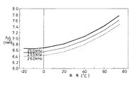
これは、表1に、温度T(℃)と、音速V(m/sec)と、25kHz,25.5kHzおよび26kHzの音波における2分の1波長λ/2(mm)との関係を示し、図5に、25kHz,25.5kHzおよび26kHzの音波において、温度(℃)と、2分の1波長λ/2(mm)との関係を示すように、従来例および比較例では、いずれも、振動体の振動周波数の2分の1波長がケースの振動体に対向する部分の内側の寸法にほぼ一致する場合があるからである。
【0019】
【表1】

なお、表1における音速V(m/sec)および音波の2分の1波長λ/2(mm)は、温度T(℃)および音波の周波数f(kHz)から次式(1)および(2)で求めた。
V = 334+0.2×T+0.007×T×T ・・・(1)
λ/2 = V/(2×f) ・・・(2)
【0021】
さらに、図4に示すグラフから明らかなように、図1ないし図3に示す実施例では、ケースなしの振動ジャイロと同様に、温度変化に対して感度が急激に変化しないことがわかる。
【0022】
また、この実施例では、図11ないし図13に示す実施例と比べて、ケース22の上部26の幅が狭く形成されるので、全体が小型になる。
【0023】
図6は図1に示す実施例の変形例を示す斜視図である。図1に示す実施例では、ケース22の上部26の長手方向における両端部の内側および外側の面が、それぞれ外側に湾曲されているが、図6に示す実施例では、ケース22の上部26の長手方向における両端部の内側および外側の面が、それぞれ傾斜面状に形成される。
図6の実施例でも、図1に示す実施例と同様に、温度変化に対して、感度が急激に変化せず、回転角速度を正確に測定することができる。さらに、図6に示す実施例でも、図11ないし図13に示す従来例と比べて、全体が小型になる。
【0024】
図7は図6に示す実施例の変形例を示す斜視図であり、図8は図7の線VIII−VIIIにおける断面図である。図7および図8に示す実施例では、図6に示す実施例と比べて、特に、ケース22の上部26の幅方向における両端部の内側および外側の面がそれぞれ傾斜面状に形成される。
図7および図8に示す実施例でも、温度変化に対して、感動が急激に変化せず、回転角速度を正確に検出することができるとともに、全体が小型になる。
【0025】
図9はこの発明の他の実施例の示す斜視図である。上述の各実施例では、ケース22の上部26の長手方向における一端から他端にわたって幅が狭く形成されているが、図9に示す実施例では、振動体14に対向するケース22の上部26において、その長手方向における中央部のみの内側および外側の幅が狭く形成される。この場合、ケース22の上部26の長手方向における中央部は、内側および外側の面がそれぞれ傾斜面状に形成される。また、図9に示す実施例では、ケース22の上部26の長手方向における両端部の内側および外側の面が、それぞれ外側に湾曲される。
図9に示す実施例でも、温度変化に対して、感度が急激に変化せず、回転角速度を正確に検出することができる。
【0026】
図10はこの発明の別の実施例を示す斜視図である。上述の各実施例では、ケース22の上部26の幅が狭く形成されているが、図10に示す実施例では、ケース22において、振動体14と幅方向に対向する部分を含む長円形状の中央部分28のみの幅が狭く形成される。
図10に示す実施例でも、温度変化に対して、感度が急激に変化せず、回転角速度を正確に検出することができる。
【0027】
なお、上述の各実施例では、正3角柱状の振動体が用いられているが、この発明では、円柱状の振動体、4角柱状の振動体、あるいは他の柱状の振動体が用いられてもよい。
【0028】
また、上述の各実施例では、3つの圧電素子が用いられるが、この発明では、駆動用かつ検出用の2つの圧電素子のみが用いられてもよく、使用する圧電素子の数を任意に変更してもよい。
【0030】
また、上述の各実施例では、振動体14の振動周波数が約25.5kHzであるが、この発明は、他の振動周波数で振動する振動体を有する振動ジャイロにも適用可能である。
【0031】
さらに、上述の各実施例では、基板とケースとで振動子などを封止しているが、ケースのみで振動子および基板などを封止するようにしてもよい。
【図面の簡単な説明】
【図1】この発明の一実施例を示す斜視図である。
【図2】図1の線II−IIにおける断面図である。
【図3】図2の線III−IIIにおける断面図である。
【図4】図1ないし図3に示す実施例、図11ないし図13に示す従来例、その従来例においてケースの幅方向における内側の寸法を広げた比較例、およびケースなしの振動ジャイロの温度変化に対する感度変化の特性を示すグラフである。
【図5】25kHz,25.5kHzおよび26kHzの音波において、温度と2分の1波長との関係を示すグラフである。
【図6】図1に示す実施例の変形例を示す斜視図である。
【図7】図6に示す実施例の変形例を示す斜視図である。
【図8】図7の線VIII−VIIIにおける断面図である。
【図9】この発明の他の実施例を示す斜視図である。
【図10】この発明の別の実施例を示す斜視図である。
【図11】従来の振動ジャイロの一例を示す斜視図である。
【図12】図11の線XII−XIIにおける断面図である。
【図13】図11の線XIII−XIIIにおける断面図である。
【符号の説明】
10 振動ジャイロ
12 振動子
14 振動体
16a,16b,16c 圧電素子
18a,18b 支持部材
20 基板
22 ケース[0001]
[Industrial application fields]
The present invention relates to a vibration gyro and, more particularly, to a vibration gyro used in, for example, a camera shake prevention system mounted on a VTR camera.
[0002]
[Prior art]
11 is a perspective view showing an example of a conventional vibrating gyroscope, FIG. 12 is a sectional view taken along line XII-XII in FIG. 11, and FIG. 13 is a sectional view taken along line XIII-XIII in FIG. The vibrating
[0003]
In the
When the vibrating
[0004]
[Problems to be solved by the invention]
However, in the vibrating
[0005]
Therefore, the main object of the present invention is to provide a vibrating gyroscope whose sensitivity does not change rapidly with respect to temperature change.
[0006]
[Means for Solving the Problems]
This invention includes a columnar vibrating body, in including the vibrating gyroscope a case covering the vibrator, the portion facing to the vibrating body of the case, the orthogonal to the vibration direction of the vibrating body and the vibrating body at no rotation shaft This is a vibration gyro in which the inner dimension in the direction orthogonal to the direction is narrower than the entire width of the case, and is different from an integral multiple of one half of the wavelength of the sound wave at the vibration frequency of the vibrating body.
[0007]
[Action]
In the portion of the case facing the vibrating body, the inner dimension in the direction perpendicular to the vibration direction of the vibrating body when not rotating and perpendicular to the axial direction of the vibrating body is set to be narrower than the entire width of the case, Since the frequency is different from an integral multiple of one half of the wavelength of the sound wave, even if the temperature changes during rotation of the vibrating gyroscope, the vibrating body does not resonate with the case, and the sensitivity does not change abruptly.
[0008]
【The invention's effect】
According to the present invention, it is possible to obtain a vibrating gyroscope whose sensitivity does not change suddenly with respect to a temperature change. Therefore, the vibration gyro according to the present invention can accurately detect the rotational angular velocity with respect to the temperature change.
[0009]
The above object, other objects, features and advantages of the present invention will become more apparent from the following detailed description of embodiments with reference to the drawings.
[0010]
【Example】
1 is a perspective view showing an embodiment of the present invention, FIG. 2 is a sectional view taken along line II-II in FIG. 1, and FIG. 3 is a sectional view taken along line III-III in FIG. The vibrating
[0011]
The
[0012]
[0013]
The vicinities of the two node points of the vibrating
[0014]
In the
[0015]
The
[0016]
In the vibrating
[0017]
FIG. 4 shows the embodiment shown in FIGS. 1 to 3, the conventional example shown in FIGS. 11 to 13, the comparative example in which the inner dimension in the width direction of the case is expanded to 6.8 mm, and the case without the case. It is a graph which shows the characteristic of the sensitivity change with respect to the temperature change of a vibration gyro.
[0018]
As is clear from the graph shown in FIG. 4, in the conventional example and the comparative example, the sensitivity changes rapidly with respect to the temperature change.
This shows the relationship between the temperature T (° C.), the sound velocity V (m / sec), and the half wavelength λ / 2 (mm) in the sound waves of 25 kHz, 25.5 kHz and 26 kHz in Table 1, FIG. 5 shows the relationship between temperature (° C.) and half wavelength λ / 2 (mm) in sound waves of 25 kHz, 25.5 kHz, and 26 kHz. This is because the half wavelength of the vibration frequency of the vibrating body may substantially match the inner dimension of the portion of the case facing the vibrating body.
[0019]
[Table 1]
Note that the sound velocity V (m / sec) and the half wavelength λ / 2 (mm) of the sound wave in Table 1 are expressed by the following equations (1) and (2) from the temperature T (° C.) and the sound wave frequency f (kHz). ).
V = 334 + 0.2 × T + 0.007 × T × T (1)
λ / 2 = V / (2 × f) (2)
[0021]
Further, as is apparent from the graph shown in FIG. 4, in the example shown in FIGS. 1 to 3, it can be seen that the sensitivity does not change abruptly with respect to the temperature change as in the case of the vibration gyro without the case.
[0022]
In this embodiment, the width of the
[0023]
FIG. 6 is a perspective view showing a modification of the embodiment shown in FIG. In the embodiment shown in FIG. 1, the inner and outer surfaces of both end portions in the longitudinal direction of the
In the embodiment shown in FIG. 6, as in the embodiment shown in FIG. 1, the sensitivity does not change rapidly with respect to the temperature change, and the rotational angular velocity can be accurately measured. In addition, the embodiment shown in FIG. 6 is smaller in size as compared with the conventional example shown in FIGS.
[0024]
FIG. 7 is a perspective view showing a modification of the embodiment shown in FIG. 6, and FIG. 8 is a sectional view taken along line VIII-VIII in FIG. In the embodiment shown in FIGS. 7 and 8, in particular, the inner and outer surfaces of both ends in the width direction of the
Also in the embodiment shown in FIGS. 7 and 8, the sensitivity does not change rapidly with respect to the temperature change, the rotational angular velocity can be accurately detected, and the whole is downsized.
[0025]
FIG. 9 is a perspective view showing another embodiment of the present invention. In each of the above-described embodiments, the width is narrowed from one end to the other end in the longitudinal direction of the
Also in the embodiment shown in FIG. 9, the sensitivity does not change rapidly with respect to the temperature change, and the rotational angular velocity can be accurately detected.
[0026]
FIG. 10 is a perspective view showing another embodiment of the present invention. In each of the embodiments described above, the width of the
Also in the embodiment shown in FIG. 10, the sensitivity does not change rapidly with respect to the temperature change, and the rotational angular velocity can be accurately detected.
[0027]
In each of the embodiments described above, a regular triangular columnar vibrating body is used. However, in the present invention, a columnar vibrating body, a quadrangular columnar vibrating body, or another columnar vibrating body is used. May be.
[0028]
In each of the embodiments described above, three piezoelectric elements are used. However, in the present invention, only two piezoelectric elements for driving and detection may be used, and the number of piezoelectric elements to be used is arbitrarily changed. May be.
[0030]
In each of the above-described embodiments, the vibration frequency of the vibrating
[0031]
Furthermore, in each of the above-described embodiments, the vibrator and the like are sealed with the substrate and the case, but the vibrator and the board may be sealed only with the case.
[Brief description of the drawings]
FIG. 1 is a perspective view showing an embodiment of the present invention.
FIG. 2 is a cross-sectional view taken along line II-II in FIG.
3 is a cross-sectional view taken along line III-III in FIG.
FIG. 4 shows the embodiment shown in FIG. 1 to FIG. 3, the conventional example shown in FIG. 11 to FIG. 13, the comparative example in which the inner dimension in the width direction of the case is widened, and the temperature of the vibrating gyroscope without the case. It is a graph which shows the characteristic of the sensitivity change with respect to a change.
FIG. 5 is a graph showing the relationship between temperature and half wavelength for sound waves of 25 kHz, 25.5 kHz, and 26 kHz.
6 is a perspective view showing a modification of the embodiment shown in FIG. 1. FIG.
7 is a perspective view showing a modification of the embodiment shown in FIG. 6. FIG.
8 is a cross-sectional view taken along line VIII-VIII in FIG.
FIG. 9 is a perspective view showing another embodiment of the present invention.
FIG. 10 is a perspective view showing another embodiment of the present invention.
FIG. 11 is a perspective view showing an example of a conventional vibrating gyroscope.
12 is a cross-sectional view taken along line XII-XII in FIG.
13 is a cross-sectional view taken along line XIII-XIII in FIG.
[Explanation of symbols]
DESCRIPTION OF
Claims (1)
前記振動体を覆うケースを含む振動ジャイロにおいて、
前記ケースの前記振動体に対向する部分において、無回転時の前記振動体の振動方向に直交しかつ前記振動体の軸方向に直交する方向における内側の寸法を、ケース全幅より狭い幅とし、前記振動体の振動周波数における音波の波長の2分の1の整数倍と異なるようにしたことを特徴とする、振動ジャイロ。In a vibrating gyroscope including a columnar vibrating body and a case covering the vibrating body ,
In the portion facing the vibrating body of the case , the inner dimension in the direction perpendicular to the vibration direction of the vibrating body at non-rotation and perpendicular to the axial direction of the vibrating body is set to be a width narrower than the full width of the case, A vibrating gyroscope characterized by being different from an integral multiple of one half of the wavelength of a sound wave at the vibration frequency of the vibrating body.
Priority Applications (4)
| Application Number | Priority Date | Filing Date | Title |
|---|---|---|---|
| JP30484292A JP3627247B2 (en) | 1992-10-16 | 1992-10-16 | Vibrating gyro |
| EP93116443A EP0592987B1 (en) | 1992-10-16 | 1993-10-11 | Vibratory gyroscope |
| DE69315531T DE69315531T2 (en) | 1992-10-16 | 1993-10-11 | Vibrator rotary sensor |
| US08/135,332 US5479822A (en) | 1992-10-16 | 1993-10-13 | Casing for a vibratory gyroscope |
Applications Claiming Priority (1)
| Application Number | Priority Date | Filing Date | Title |
|---|---|---|---|
| JP30484292A JP3627247B2 (en) | 1992-10-16 | 1992-10-16 | Vibrating gyro |
Publications (2)
| Publication Number | Publication Date |
|---|---|
| JPH06129857A JPH06129857A (en) | 1994-05-13 |
| JP3627247B2 true JP3627247B2 (en) | 2005-03-09 |
Family
ID=17937925
Family Applications (1)
| Application Number | Title | Priority Date | Filing Date |
|---|---|---|---|
| JP30484292A Expired - Lifetime JP3627247B2 (en) | 1992-10-16 | 1992-10-16 | Vibrating gyro |
Country Status (4)
| Country | Link |
|---|---|
| US (1) | US5479822A (en) |
| EP (1) | EP0592987B1 (en) |
| JP (1) | JP3627247B2 (en) |
| DE (1) | DE69315531T2 (en) |
Family Cites Families (2)
| Publication number | Priority date | Publication date | Assignee | Title |
|---|---|---|---|---|
| FR2554225B1 (en) * | 1983-11-02 | 1985-12-27 | Crouzet Badin Sa | ACOUSTIC GYROMETER |
| GB2208318B (en) * | 1987-07-24 | 1991-11-06 | Yazaki Corp | Vibrational angular velocity sensor |
-
1992
- 1992-10-16 JP JP30484292A patent/JP3627247B2/en not_active Expired - Lifetime
-
1993
- 1993-10-11 DE DE69315531T patent/DE69315531T2/en not_active Expired - Lifetime
- 1993-10-11 EP EP93116443A patent/EP0592987B1/en not_active Expired - Lifetime
- 1993-10-13 US US08/135,332 patent/US5479822A/en not_active Expired - Lifetime
Also Published As
| Publication number | Publication date |
|---|---|
| JPH06129857A (en) | 1994-05-13 |
| DE69315531T2 (en) | 1998-06-10 |
| DE69315531D1 (en) | 1998-01-15 |
| US5479822A (en) | 1996-01-02 |
| EP0592987B1 (en) | 1997-12-03 |
| EP0592987A1 (en) | 1994-04-20 |
Similar Documents
| Publication | Publication Date | Title |
|---|---|---|
| JPH063455B2 (en) | Vibrating gyro | |
| JPH0545167A (en) | Vibration gyro | |
| JP3627247B2 (en) | Vibrating gyro | |
| JPH0695099B2 (en) | Vibrating gyro | |
| JPH08146033A (en) | Acceleration sensor | |
| JPH02266215A (en) | Vibrator | |
| JPH08247770A (en) | Vibration gyroscope | |
| JP2508384B2 (en) | Angular velocity sensor | |
| JPH08327653A (en) | Acceleration sensor | |
| JP2006258527A (en) | Gyro element, gyrosensor, and manufacturing method of gyro element | |
| JP2508382B2 (en) | Angular velocity sensor | |
| JP3129117B2 (en) | Acceleration sensor | |
| GB2272056A (en) | Solid-state resonator device | |
| JP2536151B2 (en) | Vibrating gyro | |
| JPH0765898B2 (en) | Vibrating gyro | |
| JPH05280990A (en) | Vibration gyro | |
| JPH06241815A (en) | Vibration gyro | |
| JPH08201067A (en) | Angular speed sensor | |
| JPH10300477A (en) | Angular velocity sensor | |
| JPH10206161A (en) | Angular velocity sensor | |
| JPH1026531A (en) | Vibrational gyro | |
| JPH11257966A (en) | Angular velocity sensor | |
| JPH04353714A (en) | Angular-velocity sensor | |
| JPH07318352A (en) | Vibrating gyro | |
| JPH08271264A (en) | Vibrating gyro |
Legal Events
| Date | Code | Title | Description |
|---|---|---|---|
| A521 | Request for written amendment filed |
Free format text: JAPANESE INTERMEDIATE CODE: A523 Effective date: 20041007 |
|
| A61 | First payment of annual fees (during grant procedure) |
Free format text: JAPANESE INTERMEDIATE CODE: A61 Effective date: 20041129 |
|
| R150 | Certificate of patent or registration of utility model |
Free format text: JAPANESE INTERMEDIATE CODE: R150 |
|
| FPAY | Renewal fee payment (event date is renewal date of database) |
Free format text: PAYMENT UNTIL: 20071217 Year of fee payment: 3 |
|
| FPAY | Renewal fee payment (event date is renewal date of database) |
Free format text: PAYMENT UNTIL: 20081217 Year of fee payment: 4 |
|
| FPAY | Renewal fee payment (event date is renewal date of database) |
Free format text: PAYMENT UNTIL: 20081217 Year of fee payment: 4 |
|
| FPAY | Renewal fee payment (event date is renewal date of database) |
Free format text: PAYMENT UNTIL: 20091217 Year of fee payment: 5 |
|
| FPAY | Renewal fee payment (event date is renewal date of database) |
Free format text: PAYMENT UNTIL: 20101217 Year of fee payment: 6 |
|
| FPAY | Renewal fee payment (event date is renewal date of database) |
Free format text: PAYMENT UNTIL: 20101217 Year of fee payment: 6 |
|
| FPAY | Renewal fee payment (event date is renewal date of database) |
Free format text: PAYMENT UNTIL: 20111217 Year of fee payment: 7 |
|
| FPAY | Renewal fee payment (event date is renewal date of database) |
Free format text: PAYMENT UNTIL: 20111217 Year of fee payment: 7 |
|
| FPAY | Renewal fee payment (event date is renewal date of database) |
Free format text: PAYMENT UNTIL: 20121217 Year of fee payment: 8 |
|
| EXPY | Cancellation because of completion of term |