JP3627100B2 - Digestion gas purification method - Google Patents
Digestion gas purification method Download PDFInfo
- Publication number
- JP3627100B2 JP3627100B2 JP2000252542A JP2000252542A JP3627100B2 JP 3627100 B2 JP3627100 B2 JP 3627100B2 JP 2000252542 A JP2000252542 A JP 2000252542A JP 2000252542 A JP2000252542 A JP 2000252542A JP 3627100 B2 JP3627100 B2 JP 3627100B2
- Authority
- JP
- Japan
- Prior art keywords
- digestion gas
- gas
- purification agent
- digestion
- gas purification
- Prior art date
- Legal status (The legal status is an assumption and is not a legal conclusion. Google has not performed a legal analysis and makes no representation as to the accuracy of the status listed.)
- Expired - Lifetime
Links
Images


Description
【0001】
【発明の属する技術分野】
本発明は、下水汚泥の消化過程から発生するシロキサン化合物を含有する消化ガスの精製剤および前記消化ガスの精製方法に関する。
【0002】
【従来の技術】
近年、地球温暖化防止対策のひとつとしてCO2削減が推進されており、例えば、下水処理場においては発電設備を設置して電力を自給・買電することにより、エネルギーの効率的利用とCO2排出削減とを図るケースが増加しつつある。
【0003】
すなわち、下水処理施設では、集積した下水を濃縮処理して各種有機物を含有する汚泥を得て、これを微生物の作用により嫌気性消化する。この過程で得られたメタンを主とする可燃性ガス(消化ガス)を、ガスエンジンおよびガスタービン等の発電設備に供して電力を得る方式が主流となりつつある。
【0004】
しかしながら、下水場の普及率向上や生活形態の変化に伴なって、シャンプーやリンス等の頭髪仕上げ剤、カーワックスなど撥水剤などの消費が増加し、これらに含有されているシロキサン化合物が下水中に多量に流下するようになってきた。
【0005】
なお、シロキサン化合物とは、シロキサン結合(Si−O−Si)を基本骨格とした鎖状または環状構造の化合物をさす。鎖状化合物としては、例えば、メトキシトリメチルシラン、ジメトキシジメチルシラン、ヘキサメチルジシロキサン、オクタメチルトリシロキサン、デカメチルテトラシロキサン、およびドデカメチルペンタシロキサン等が挙げられ、環状化合物としては、例えばヘキサメチルシクロトリシロキサン(D3体)、オクタメチルシクロテトラシロキサン(D4体)、デカメチルシクロペンタシロキサン(D5体)、およびドデカメチルシクロヘキサシロキサン(D6体)などが挙げられる。ここに列挙した化合物は、化合物中の官能基がメチル基で構成されているが、メチル基に類する炭化水素基で置換された化合物、または水素の代わりにフッ素、塩素等で置換された化合物も含まれ、さらには分子量の大きい多重合化合物も存在する。
【0006】
シロキサン化合物は、その多くは水に不溶であるため汚泥に吸着した形で下水中に存在するが、引き続いて行なわれる消化過程で消化ガス側に揮散する。すなわち、シロキサン化合物は、発電用の燃料ガスであるメタンとともに存在して、その後段のガスエンジンに流入していた。ガスエンジンに流入したシロキサン化合物は、エンジン内の燃焼室でシリカ(SiO2)となって、エンジン内のシリンダーヘッドやその他各部品に付着・析出する。その結果、エンジンを摩耗・劣化させてしまうという不具合を生じていた。
【0007】
また、さらにガスエンジン等の発電設備を経たエンジン排ガスは、例えば窒素酸化物処理のため、脱硝触媒塔に導入されて処理されるが、この排ガス中にシリカ(SiO2)が含まれているために、触媒の表面に排ガス中の粉体状シリカ(SiO2)が析出する。粉体状シリカは、こうして触媒の表面を覆い、その一部は触媒の内部まで浸透してしまうため、触媒活性が劣化して所望の窒素酸化物除去が達成されないという不具合も生じていた。
【0008】
従来は、上述したシロキサン化合物に起因して生じる問題を直接回避する有効な手段を実施せずに、別途、エンジンの保守点検頻度、脱硝触媒の交換頻度を多くすることによって対応していたのが現状である。
【0009】
【発明が解決しようとする課題】
上述したように、下水処理場の消化過程から発生するシロキサン化合物を含有する消化ガスは、後段のガスエンジンでの燃焼過程においてエンジン内でシリカ(SiO2)を発生させるので、エンジンの各部品の摩耗・劣化が生じる。さらに後段の脱硝触媒においても、シリカ(SiO2)は触媒表面を覆って脱硝性能を劣化させるという不具合を生じていた。
【0010】
また一方、有機溶剤や有機シリコンを扱う印刷工場など各種工場における排ガスや空調排ガスなどにも、シロキサン化合物が含まれており、こうしたシロキサン化合物を除去するために、燃焼手段、溶媒吸収法などが実施されていた。しかしながら、シロキサン化合物が低濃度であるために完全燃焼することが困難であり、燃焼による手段では十分に除去することができない。また一方、溶媒吸収法では、シロキサン化合物を吸収させるための溶媒が別途必要とされ、しかも吸収済みの溶媒処理が煩雑でコストが甚大であるという問題を生じていた。
【0011】
本発明は、下水汚泥消化ガス中のシロキサン化合物を安価に効率よく除去するための消化ガス精製剤を用いた消化ガスの精製方法を提供することを目的とする。
【0012】
【課題を解決するための手段】
上記課題を解決するために、本発明は、シロキサン化合物を含有する下水汚泥消化ガス中に粉末状の消化ガス精製剤を吹き込んで、前記下水汚泥消化ガスに前記消化ガス精製剤を同伴させる工程と、
前記下水汚泥消化ガスに同伴された前記消化ガス精製剤を、ろ過集塵機により集塵して前記消化ガス精製剤の堆積層を形成する工程と、
前記消化ガス精製剤の堆積層に前記下水汚泥消化ガスを通過させて、前記消化ガス精製剤にシロキサン化合物を吸着させることにより、前記ガス中に含まれるシロキサン化合物を除去する工程とを具備し、
前記消化ガス精製剤は、比表面積が500m 2 /g以上および10Å〜20Åの範囲の細孔径を有する細孔の積算容積が0.1cm 3 /g以上となるように賦活処理が施された炭素質からなることを特徴とする消化ガスの精製方法を提供する。
【0014】
さらに本発明は、粒状、破砕状、または成形状の消化ガス精製剤を容器に充填して充填層を準備する工程と、
前記充填層に、シロキサン化合物としてオクタメチルシクロテトラシロキサンおよびデカメチルシクロペンタシロキサンを含有する下水汚泥消化ガスを通過させて、前記消化ガス精製剤にシロキサン化合物を吸着させることにより、前記ガス中に含まれるシロキサン化合物を除去する工程とを具備し、
前記消化ガス精製剤は、比表面積が500m2/g以上および10Å〜20Åの範囲の細孔径を有する細孔の積算容積が0.1cm3/g以上となるように賦活処理が施された炭素質からなることを特徴とする消化ガスの精製方法を提供する。
【0015】
本発明の消化ガス精製剤は、その表面が酸性となるように酸処理が施されたものであることが好ましい。
【0016】
本発明を用いてシロキサン化合物が除去され精製されたガスは、引き続いて行なわれるプロセスにおいて、シロキサン化合物に起因した各種の不具合を回避することが可能となる。
【0017】
下水汚泥消化ガスには、下水由来のシロキサン化合物、特に、オクタメチルシクロテトラシロキサンおよびデカメチルシクロペンタシロキサンが含有されている。このため、消化ガスを用いて発電する際には、ガスエンジン内部でシリカ(SiO2)析出に起因したエンジン部品の摩耗・劣化、さらには脱硝触媒の劣化といった不具合が避けられなかった。本発明により、消化ガス中のシロキサン化合物を効率よく吸着除去してエンジンに投入される前に精製されるので、エンジンの保守点検頻度および脱硝触媒の交換頻度を低減することが可能となる。
【0018】
【発明の実施の形態】
以下、図面を参照して本発明を詳細に説明する。
【0019】
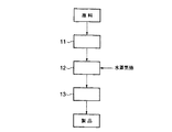
図1は、本発明の消化ガス精製剤を製造するためのプロセスの一例を表わす概略図である。
【0020】
原料である炭素質としては、石油系、石炭系、および木炭系の各種の炭素含有物を用いることができる。こうした原料は、前処理工程11として、乾燥、炭化、破砕、整粒の各工程を経た後、賦活工程12へ導入される。賦活工程12においては、酸化性気体として機能する水蒸気が賦活剤として用いられ、ロータリキルンで所定時間、所定温度で賦活処理が施されて、細孔を有する多孔質体が得られる。この際の賦活処理は、得られる多孔質体が次の2つの条件の少なくとも一方を満たすように行なわれる。すなわち、(1)比表面積が500m2/g以上である、(2)10Å〜20Åの範囲の細孔径を有する細孔の積算容積が0.1cm3/g以上となる、という条件である。これを達成するためには、例えば、所定温度で所定時間、炭素重量の減量が例えば60〜70%となるように賦活処理が施される。
【0021】
多孔質体となった炭素質は、続いて後処理工程13へ導入され、酸洗、粉砕、分級の各工程を経て本発明の消化ガス精製剤が得られる。
【0022】
賦活工程12で用いられる賦活剤は、公知の通り水蒸気のみでもよいが、必要に応じて二酸化炭素や空気を用いてもよい。賦活温度は750〜1000℃の範囲とすることができる。また、消化ガス精製剤を成形体として用いる場合には、前処理工程11においてバインダーを別途用いて混和・成形・焼成する必要がある。
【0023】
薬品添加による賦活法を採用する場合には、原料として主に木質系未炭化物が用いられる。木質系未炭化物は、前処理工程11において、塩化亜鉛、リン酸などの薬品が添加された後、賦活工程12では500〜700℃の温度で賦活処理されて、本発明の消化ガス精製剤が得られる。
【0024】
以上のように、従来知られているような活性炭の製法と同等の手法を用いて、本発明の消化ガス精製剤を製造することができる。
【0025】
一般に、炭素系多孔質体の薬剤を製造する際の細孔の発達に重要なのは、その原料の種類、炭化・乾留方法、賦活剤の種類、賦活薬品の浸漬比、賦活温度、賦活時間(炭素重量減量)、および炉形式などの各種因子である。これらの因子が相互に影響しあって、炭素系多孔質体の細孔容積や比表面積といった性質が決定される。言い換えると、賦活処理の際の温度や時間は、得られる多孔質体の性能を決定する支配的な因子ではあるものの、原料や賦活剤の種類、賦活炉の種類、施される前処理方法によって、同じ賦活工程を経ても、得られる多孔質体の性能が大きく異なることが多いのである。
【0026】
このような事情から、本発明においては、製造方法は特に限定せずに、製造後の細孔分布および比表面積を用いて消化ガス精製剤を特定している。具体的には本発明の消化ガス精製剤は、比表面積が500m2/g以上および10Å〜20Åの範囲の細孔径を有する細孔の積算容積が0.1cm3/g以上の消化ガス精製剤である。こうした性質を付与するよう、好適な温度および時間で賦活処理を施して、本発明の消化ガス精製剤が得られる。
【0027】
また、活性炭の製造炉を有しない場合には、比表面積、細孔分布を測定し、比表面積が500m2/g以上および10Å〜20Åの範囲の細孔径を有する細孔の積算容積が0.1cm3/g以上となる市販の活性炭を消化ガス精製剤として採用してもよい。
【0028】
いずれにせよ、本発明の消化ガス精製剤は、比表面積が500m2/g以上、および/または10Å〜20Åの範囲の細孔径を有する細孔の積算容積が0.1cm3/g以上となるように賦活処理が施された炭素質からなる精製剤である。
【0029】
図2は、本発明にかかる消化ガス精製剤の細孔径と細孔容積との関係の一例を表わすグラフ図である。図2には、細孔径が10〜20Åの範囲の細孔容積が約0.21cm3/g(0.34−0.13cm3/g)であることが示されている。
【0030】
こうした細孔容積を有する本発明の消化ガス精製剤は、その表面が酸性となるように酸処理を施したものであることが好ましい。
【0031】
酸処理としては、塩酸、硝酸、硫酸等の無機酸による水洗処理、酸添加処理、および酸浸漬処理等を施すことができる。酸処理を行なうことによって、精製剤に含まれる不純物であるアルカリ塩類等を流し出し、続いて250℃以下の温度にて乾燥することにより、精製剤の表面を酸性に保持することができる。表面が酸性の精製剤を用いることによって、シロキサン化合物を選択的に吸着することが可能となるが、これについては後述する。
【0032】
図3は、本発明の消化ガスの精製方法を説明するための概略図である。図3においては周辺機器、詳細機器の記載は省略してあるが、この概略図は、本発明を適用した下水汚泥消化ガス発電システムの一例を表わすということができる。
【0033】
下水処理場にて集積した下水は、濃縮その他の処理が施され、ここで得られた各種有機物を含む汚泥は、微生物の作用により消化ガス発生装置(卵型消化槽など、図示せず)にて嫌気性消化される。この過程で得られたメタンを主とする可燃性ガス(消化ガス)Gdは、脱硫処理、ミスト除去処理等が施された後、消化ガスタンク1に貯留される。
【0034】
消化ガスタンク1に貯留された消化ガスには、下水由来のシロキサン化合物が、例えば10〜200mg/m3の濃度で含まれている。消化ガスタンク1に貯留された消化ガスは、図示するように後段のろ過式集塵機2に導入され、その際通過する配管において、本発明の消化ガス精製剤が精製剤供給装置5から噴霧・供給される。
【0035】
消化ガス精製剤を噴霧するための精製剤供給装置5としては、公知の供給手段を用いることができ、例えばスクリューコンベア等の機械的搬送手段、あるいは気体に同伴させて供給する気体搬送手段を採用することができるが、気密性を確保する必要がある。
【0036】
消化ガス精製剤は粉状として用いられ、消化ガスに同伴されて後段のろ過式集塵機2により集塵される。ろ過式集塵機2に集塵された消化ガス精製剤は、このろ過式集塵機2内のろ布(図示せず)表面に堆積して、逆洗されるまでの一定時間、消化ガス精製剤の堆積層を形成する。消化ガスがこの堆積層を通過する際に、消化ガスに含まれるシロキサン化合物は、消化ガス精製剤の吸着作用により吸着除去される。
【0037】
ここで、ろ過式集塵機2は、織布、フェルトその他からなるろ布、ろ布を内側から支えるリテーナ、ろ布に堆積した集塵物(消化ガス精製剤)を逆洗するための逆洗装置、および逆洗で払い落とされた集塵物を貯留する集塵物ホッパなどから構成される公知のバグフィルタ装置とすることができる。ただし、ろ布は、硫化水素の流入を考慮して耐酸性の材質を採用し、可燃性ガス(消化ガス)を扱うので装置全体を密閉式とすることが好ましい。また、逆洗は窒素または消化ガスによるパルスジェット方式とすることが望まれる。集塵物を貯留する集塵物ホッパは、密閉式のロータリーバルブを採用して連続的に回収してもよいし、定期点検時に回収してもよい。
【0038】
ろ過式集塵機2に形成された消化ガス精製剤の堆積層を通過することにより精製された消化ガスは、連通するガスエンジン3に導入される。なお、ガスエンジン3は、発電設備の例示であり、ガスタービン、燃焼ボイラ等のその他の発電設備であってもよい。
【0039】
ガスエンジン3内で燃焼過程を経た排ガスは、脱硝触媒塔4に導入され、ここで排ガス中の窒素化合物が除去された後、煙突(図示せず)を介して大気放散される。脱硝触媒塔4は、発電設備の後段に通常設置されるが、希薄燃焼その他の工夫により、窒素酸化物濃度が低い場合には設置を省略される場合があることと、充填する触媒はハニカム形状その他が用いられ、脱硝に供される触媒であればよく、特に材質を限定するものではない。
【0040】
なお、図面には示していないが、ブースター(ガス圧縮機)は、ろ過式集塵機2とガスエンジン3との間に設置することができ、減湿器(クーラー、ドレンセパレーター、ミストセパレーター等)は、ろ過式集塵機2の前または後に必要に応じて設置することができる。
【0041】
ガスエンジン3に導入された消化ガスは、消化ガス精製剤の堆積層を通過したことによりシロキサン化合物を含有しないので、ガスエンジン内部にシリカ(SiO2)を析出させることはなく、従来のようなエンジン部品の摩耗・劣化を避けることができる。さらに、脱硝触媒塔4触媒の劣化の不具合も、ガス中のシロキサン化合物が除去されたことにより未然に回避することが可能となる。その結果、ガスエンジン3の保守点検頻度および脱硝触媒塔4の触媒の交換頻度を、著しく低減することが可能となる。
【0042】
本発明において消化ガスGd中に含有されるシロキサン化合物とは、シロキサン結合(Si−O−Si)を基本骨格とした鎖状または環状構造の化合物をさす。鎖状化合物としては、例えば、メトキシトリメチルシラン、ジメトキシジメチルシラン、ヘキサメチルジシロキサン、オクタメチルトリシロキサン、デカメチルテトラシロキサン、およびドデカメチルペンタシロキサンが挙げられ、環状化合物としては、例えばヘキサメチルシクロトリシロキサン(D3体)、オクタメチルシクロテトラシロキサン(D4体)、デカメチルシクロペンタシロキサン(D5体)、およびドデカメチルシクロヘキサシロキサン(D6体)が挙げられる。なお、シロキサン化合物中の官能基はメチル基で構成される必要はなく、メチル基に類する炭化水素基で置換されていてもよい。あるいは、水素の代わりにフッ素、塩素等で置換されたシロキサン化合物も含まれ、さらには分子量の大きい多重合化合物も含まれる。
【0043】
これらのうち、下水汚泥消化ガスに含まれるシロキサン化合物は、特に、環状構造であるオクタメチルシクロテトラシロキサン(D4体)およびデカメチルシクロペンタシロキサン(D5体)が支配的に多く検知されることが本発明者らの調査により判明した。すなわち、これらの化合物を選択的あるいは優先的に吸着除去することによって、上述した効果を確実に得ることができるのである。
【0044】
これを達成するために、本発明者らは鋭意検討の結果、上述したような化合物の分子径、すなわち、D4体:約10Å、D5体:約12Åを推定し、これに相当しかつ吸着効果が大きいと帰結した消化ガス精製剤の細孔径を、10〜20Åと結論するに至った。また本発明者らは、消化ガス精製剤の比表面積を500m2/g以上、より好ましくは1000m2/g以上とするのが有効であると帰結したのである。このように構成することによって、消化ガス精製剤におけるD4体およびD5体の平衡吸着量を、例えば20〜60℃の条件下で、0.15〜0.5g/gと大きくすることが可能となる。したがって、すり抜け(未吸着のまま放出されること)がなく、吸着破過に達する時間を長く保持することが可能となった。
【0045】
ここで図4および図5に、本発明者らの研究調査結果の一例を示す。
【0046】
図4は、消化ガス精製剤の比表面積と、シロキサン化合物の除去率および平衡吸着量との関係を示す。図4のグラフにおいて、曲線aは、消化ガス精製剤の比表面積とシロキサン化合物除去率との関係を表わし、曲線bは、消化ガス精製剤の比表面積と平衡吸着量との関係を表わしている。図4のグラフから、比表面積が500m2/g未満の消化ガス精製剤を用いた場合には、一定時間後のシロキサン化合物の除去水準(除去率および平衡吸着量)が極端に低いことが判明している。したがって、消化ガス精製剤の比表面積は500m2/g以上であることが望ましく、1000m2/g以上であることがより望ましい。
【0047】
ここで、消化ガス精製剤の比表面積は、窒素ガス吸着によるBET法、あるいはこれに準ずる方法により測定された値を採用する。
【0048】
図5のグラフは、消化ガス精製剤における10Å〜20Åの範囲の細孔容積と、シロキサン化合物除去率および平衡吸着量との関係を示す。図5のグラフにおいて、曲線cは、10Å〜20Åの範囲の細孔容積とシロキサン化合物除去率との関係を表わし、曲線dは10Å〜20Åの範囲の細孔容積と平衡吸着量との関係を表わしている。図5のグラフから、10Å〜20Åの範囲の細孔径を有する細孔の積算容量が0.1cm3/g未満である消化ガス精製剤を用いた場合には、一定時間後のシロキサン化合物の除去水準(除去率および平衡吸着量)が極端に低いことが判明している。したがって、10Å〜20Åの範囲の細孔の積算容量が0.1cm3/g以上である消化ガス精製剤を用いることが、相対的に好ましい。
【0049】
ここで、消化ガス精製剤の細孔分布は、例えば、N2ガス吸着法、アルゴンガス吸着法、および水銀圧入法などにより測定することができるが、比較的精度がよく、汎用な手法であるN2ガス吸着法を用いることが好ましい。但し、これに準ずる方法であれば採用できる。
【0050】
しかるに本発明者らは、(1)消化ガス精製剤の比表面積を500m2/g以上、さらには1000m2/g以上とする、および(2)消化ガス精製剤の10Å〜20Åの範囲の細孔径を有する細孔の積算容積を0.1cm3/g以上とする、を満たす炭素質吸着剤を消化ガス精製剤として提案した。
【0051】
言い換えると、このような本発明の消化ガス精製剤を消化ガス発電システムにおける消化ガスの精製剤として採用し、図3に関して説明したような方法で消化ガス中のシロキサン化合物を除去するので、すでに述べたような作用効果が確実に得られる。
【0052】
また、消化ガス精製剤として、酸処理を施したものを用いると、表面が酸性であるので、前段の脱硫過程でわずかに流出する硫化水素の消化ガス精製剤への吸着が抑制される。したがって、シロキサン化合物を選択的に吸着することができ、吸着破過時間を長くするという効果がある。
【0053】
図6は、本発明の消化ガスの精製方法を説明する別の例を表わす概略図であり、本発明を適用した下水汚泥消化ガス発電システムの他の例を表わす概略図ということができる。ただし図6においては、周辺機器、詳細機器の記載は省略してあり、また、図3と同一部分の構成の説明は省略する。
【0054】
消化ガスタンク1に貯留されたシロキサン化合物を含有する消化ガスGdは、本発明の消化ガス精製剤が充填された充填層6に導入され、充填層6を通過する際に、消化ガス中のシロキサン化合物が吸着除去されて、後段のガスエンジン3に導入される。
【0055】
充填層6に充填される消化ガス精製剤は、粒状、破砕状、または成形状とすることができる。この精製剤を容器に充填して充填層を形成し、充填層6を構成する。
【0056】
なお、図示しないブースター(ガス圧縮機)、減湿器(クーラー、ドレンセパレーター、ミストセパレーター等)は、ガスエンジン3の上流側であればいずれの場所でもよく、適宜設置することができる。
【0057】
ガスエンジン3に導入された消化ガスは、充填層6を通過したことによりシロキサン化合物を含有しないので、ガスエンジン内部にシリカ(SiO2)を析出させることはなく、従来のようなエンジン部品の摩耗・劣化を避けることができる。さらに、脱硝触媒塔4触媒の劣化の不具合も、ガス中のシロキサン化合物が除去されたことにより未然に回避することが可能となる。その結果、ガスエンジン3の保守点検頻度および脱硝触媒塔4の触媒の交換頻度を、著しく低減することが可能となる。
【0058】
ここで、充填層6を通過する際の消化ガスの空塔速度は、0.5m/s以下とすることが好ましい。
【0059】
消化ガス精製剤を収容した充填層6に流通する消化ガスの空塔速度が0.5m/sを越えると、ガスと消化ガス精製剤との接触効率が低下して、十分にシロキサン化合物を吸着分離することが困難になるおそれがある。0.5m/s以下の空塔速度でシロキサン化合物含有ガスを通過させることによって、充填層6出口からシロキサン化合物が排出されることなく、効率よく除去することができる。
【0060】
このことは、本発明者らの研究調査結果の一例である図7のグラフにより裏付けられる。図7は、充填層6のおけるガスの空塔速度とシロキサン化合物除去率との関係を示す。図7に示されるように、空塔速度が0.5m/sを越えると、一定時間後のシロキサン化合物の除去水準が極端に低下するので、一般には空塔速度は0.5m/s以下とすることが相対的に好ましい。ただし、空塔速度が0.5m/sを越える場合には、層高を十分長くすることなどによって、ガスと消化ガス精製剤との接触効率を高めることも可能である。
【0061】
ここで用いられる充填層6は、炭素質の消化ガス精製剤を充填でき、被処理ガスである下水汚泥消化ガスを流通できる密閉式の構造であれば、その形式は特に限定されない。例えば、固定床式、移動床式、流動床式、または多段式とすることができ、塔内のガス流れが上向流および下降流のいずれであっても同等の効果が得られる。移動床式の場合は、充填剤の連続(あるいは間欠)供給装置と排出装置とを密閉性よく設置することはいうまでもない。また、プロセス停止時に充填層6内の消化ガスをパージできるように、別途パージライン、窒素供給ライン等を設けることも必要に応じてなされる。充填層6の消化ガス精製剤は、必要に応じて、水蒸気加熱、減圧処理などの再生処理が別途なされ、繰り返し使用を行なうことができる。
【0062】
こうしたパージライン、窒素供給ラインは、図3に示したようなろ過式集塵機2を用いた場合も同様である。さらに、ろ過式集塵機2から回収された消化ガス精製剤も、上述したように必要に応じて再生処理を施すことができる。
【0063】
充填層6に充填される消化ガス精製剤は、すでに述べたように、比表面積が500m2/g以上であることが好ましく、10Å〜20Åの範囲の細孔の積算容積が0.1cm3/g以上となる細孔分布を有することが望ましい。その材質は、炭素質に加えて、例えば、ゼオライト、アルミナ等を用いても、同等の効果を得ることができる。
【0064】
【実施例】
(実施例)
図6に示した下水汚泥消化ガス発電システムの運転を行なって、運転開始3ヶ月後におけるガスエンジン3入口のシロキサン化合物濃度、ガスエンジン3内に残留するSi化合物量、およびガスエンジン後段の脱硝触媒塔4での脱硝率を調べ、得られた結果を、発電用消化ガス温度とともに下記表1にまとめる。なお、充填層6に充填される消化ガス精製剤としては活性炭を用い、10Å〜20Åの細孔の容積割合は0.21cm3/g、その比表面積は1000m2/g、表面のpHは6.0である。
【0065】
(比較例)
比較例として、図8に示す下水汚泥消化ガス発電システムの運転を行なった。図8に示すシステムは、消化ガス精製剤が充填された充填層6を設置していない以外は、図6に示したものと同様である。前述と同様に運転開始3ヶ月後におけるガスエンジン入口のシロキサン化合物濃度、ガスエンジン内に残留するSi化合物量、およびガスエンジン後段の脱硝触媒塔での脱硝率を調べ、得られた結果を発電量消化ガス温度とともに下記表1にまとめる。
【0066】
【表1】

表1に示されるように、本発明を用いてシロキサン化合物の除去を行なった実施例においては、運転3ヶ月後であってもガスエンジン3の入口、すなわち、充填層6出口のシロキサン濃度が4.5mg/m3と小さい。これに対して、シロキサン化合物の除去を行なわない比較例においては、ガスエンジン入口のシロキサン濃度は85mg/m3であり、本発明によりシロキサン濃度が著しく低減されることが確認された。
【0068】
また、実施例においては、ガスエンジン3内のシリンダーヘッド等の各エンジン部材から採取された析出物中のSi付着量は、比較例の5%程度と低い値に抑制されている。このことから、本発明の方法によりシロキサン化合物が除去された精製ガスは、エンジンの運転に何等悪影響を及ぼさないことが判明した。
【0069】
さらに実施例においては、後段の脱硝触媒塔におけるSi付着量も少なかったので、脱硝効率は57%と初期値(60%)と同等の値であった。一方、比較例においては、エンジン排ガス中のシリカ(SiO2)が触媒表面へ付着したことに起因して触媒活性が低下し、脱硝率は13%とごく低いレベルにとどまっていることがわかる。
【0070】
このように、本発明を用いることによって、消化ガス中のシロキサン化合物を十分に効率よく吸着でき、ガスエンジン内および脱硝触媒でのシロキサン由来のSi化合物(SiO2)の付着量は従来に比べて激減させることができる。その結果、ガスエンジンの保守点検頻度を低減して、長期にわたって脱硝触媒の活性を維持できることが確認された。
【0071】
【発明の効果】
以上説明したように本発明によれば、下水汚泥消化ガス中のシロキサン化合物を安価に効率よく除去することが可能な消化ガスの精製剤、およびこれを用いた消化ガスの精製方法が提供される。
【0072】
以上説明したように本発明によれば、下水汚泥消化ガス中のシロキサン化合物を安価に効率よく除去することが可能な消化ガスの精製剤を用いた消化ガスの精製方法が提供される。
【0073】
さらに、酸処理を施した消化ガス精製剤を用いた場合には、表面が酸性であるゆえ、前段の脱硫過程でわずかに流出する硫化水素の消化ガス精製剤への吸着を抑制して、シロキサン化合物を選択的に吸着することができる。したがって、吸着破過時間を長くすることが可能となる。
【0074】
本発明は、下水汚泥消化ガスのみならず、有機シリコン等を取り扱う各種工場排ガス、および空調排ガスなどのシロキサン化合物含有ガスからのシロキサン化合物の除去に適用することも可能であり、その工業的価値は大きい。
【図面の簡単な説明】
【図1】本発明の消化ガス精製剤を製造するためのプロセスの一例を表わす概略図
【図2】消化ガス精製剤の細孔径と細孔容積との関係を表わすグラフ図。
【図3】本発明の消化ガスの精製方法の一例を説明する概略図。
【図4】本発明の消化ガス剤の比表面積と、シロキサン化合物除去率および平衡吸着量との関係を表わすグラフ図。
【図5】本発明の消化ガス精製剤の10〜20Åの細孔容積と、シロキサン化合物除去率および平衡吸着量との関係を表わすグラフ図。
【図6】本発明の消化ガスの精製方法の他の例を説明する概略図。
【図7】下水汚泥消化ガスの空塔速度とシロキサン化合物除去率との関係を表わすグラフ図。
【図8】従来の下水汚泥消化ガス発電システムの構成を表わす概略図。
【符号の説明】
1…消化ガスタンク
2…ろ過式集塵機
3…ガスエンジン
4…脱硝触媒塔
5…精製剤供給装置
6…充填層
11…前処理工程
12…賦活工程
13…後処理工程
GD…消化ガス
GE…排気ガス[0001]
BACKGROUND OF THE INVENTION
The present invention relates to a purification agent for digestion gas containing a siloxane compound generated from the digestion process of sewage sludge and a method for purifying the digestion gas.
[0002]
[Prior art]
In recent years, CO is one of the measures to prevent global warming.2Reduction is being promoted. For example, in sewage treatment plants, power generation facilities are installed and electricity is self-sufficient and purchased.2Increasing cases of reducing emissions.
[0003]
That is, in the sewage treatment facility, the accumulated sewage is concentrated to obtain sludge containing various organic substances, which is anaerobically digested by the action of microorganisms. A method for obtaining electric power by using a combustible gas (digestion gas) mainly containing methane obtained in this process to a power generation facility such as a gas engine and a gas turbine is becoming mainstream.
[0004]
However, as the penetration rate of sewage plants has improved and the lifestyle has changed, the consumption of hair finishes such as shampoos and rinses and water repellents such as car wax has increased, and the siloxane compounds contained in these have become sewage. It began to flow down in large quantities.
[0005]
Note that the siloxane compound refers to a compound having a chain or cyclic structure with a siloxane bond (Si—O—Si) as a basic skeleton. Examples of the chain compound include methoxytrimethylsilane, dimethoxydimethylsilane, hexamethyldisiloxane, octamethyltrisiloxane, decamethyltetrasiloxane, and dodecamethylpentasiloxane. Examples of the cyclic compound include hexamethylcyclohexane. Examples include trisiloxane (D3 form), octamethylcyclotetrasiloxane (D4 form), decamethylcyclopentasiloxane (D5 form), and dodecamethylcyclohexasiloxane (D6 form). In the compounds listed here, the functional group in the compound is composed of a methyl group, but a compound substituted with a hydrocarbon group similar to the methyl group or a compound substituted with fluorine, chlorine or the like instead of hydrogen is also available. There are also polypolymeric compounds which are included and which have a high molecular weight.
[0006]
Most of the siloxane compounds are insoluble in water and are present in the sewage in the form of adsorbed by sludge, but volatilize to the digestion gas side in the subsequent digestion process. That is, the siloxane compound is present together with methane, which is a fuel gas for power generation, and flows into the gas engine at the subsequent stage. Siloxane compounds that flow into the gas engine are silica (SiO2) in the combustion chamber in the engine.2) And deposit on the cylinder head and other parts in the engine. As a result, the engine is worn out and deteriorated.
[0007]
Further, engine exhaust gas that has passed through a power generation facility such as a gas engine is introduced into a denitration catalyst tower for treatment, for example, for nitrogen oxide treatment.2) Contained in the exhaust gas on the surface of the catalyst.2) Precipitates. The powdery silica thus covers the surface of the catalyst, and a part of the silica penetrates into the inside of the catalyst, so that the catalyst activity is deteriorated and the desired nitrogen oxide removal cannot be achieved.
[0008]
In the past, without implementing effective means for directly avoiding the problems caused by the above-mentioned siloxane compounds, it has been dealt with by separately increasing the frequency of maintenance and inspection of the engine and the replacement frequency of the denitration catalyst. Currently.
[0009]
[Problems to be solved by the invention]
As described above, the digestion gas containing the siloxane compound generated from the digestion process of the sewage treatment plant is silica (SiO 2) in the engine during the combustion process in the latter stage gas engine.2) Will cause wear and deterioration of each part of the engine. Furthermore, silica (SiO2) Had a problem of covering the catalyst surface and denitrating performance.
[0010]
On the other hand, siloxane compounds are also contained in exhaust gas and air-conditioning exhaust gas in various factories such as printing factories that handle organic solvents and organic silicon, and in order to remove such siloxane compounds, combustion means, solvent absorption methods, etc. are implemented. It had been. However, since the siloxane compound has a low concentration, it is difficult to complete combustion, and it cannot be sufficiently removed by means of combustion. On the other hand, in the solvent absorption method, a solvent for absorbing the siloxane compound is required separately, and the solvent treatment after absorption is complicated and costs are high.
[0011]
The present invention is for removing siloxane compounds in sewage sludge digestion gas efficiently at low cost.Using digestive gas purification agentIt aims at providing the purification method of digestion gas.
[0012]
[Means for Solving the Problems]
In order to solve the above problems, the present invention provides:Blowing a powdery digestion gas purification agent into a sewage sludge digestion gas containing a siloxane compound, and entraining the digestion gas purification agent in the sewage sludge digestion gas;
Collecting the digestion gas purifier entrained in the sewage sludge digestion gas with a dust collector to form a layer of the digestion gas purifier;
Removing the siloxane compound contained in the gas by passing the sewage sludge digestion gas through the deposit layer of the digestion gas purification agent and adsorbing the siloxane compound to the digestion gas purification agent,
The digestion gas purification agent has a specific surface area of 500 m. 2 / G or more and a cumulative volume of pores having a pore diameter in the range of 10 to 20 cm is 0.1 cm Three / Digestion gas purification method comprising carbonaceous material that has been subjected to activation treatment so as to be equal to or greater than / gI will provide a.
[0014]
Furthermore, the present invention includes a step of filling a container with a granular, crushed, or molded digestive gas purification agent to prepare a packed bed;
In the packed layer, a siloxane compoundAs octamethylcyclotetrasiloxane and decamethylcyclopentasiloxaneA sewage sludge digestion gas containing, and a siloxane compound contained in the gas is removed by adsorbing the siloxane compound to the digestion gas purification agent,
The digestion gas purification agent has a specific surface area of 500 m.2/ G or moreandThe cumulative volume of pores having a pore diameter in the range of 10 to 20 cm is 0.1 cmThreeThe present invention provides a method for purifying digestion gas, characterized by comprising a carbonaceous material that has been subjected to activation treatment so as to be at least / g.
[0015]
The digestion gas purification agent of the present invention is preferably one that has been subjected to an acid treatment so that the surface thereof is acidic.
[0016]
The gas purified by removing the siloxane compound using the present invention can avoid various problems caused by the siloxane compound in the subsequent process.
[0017]
The sewage sludge digestion gas contains a siloxane compound derived from sewage, particularly octamethylcyclotetrasiloxane and decamethylcyclopentasiloxane. For this reason, when generating power using digestion gas, silica (SiO2) Problems such as wear and deterioration of engine parts and deterioration of the denitration catalyst due to precipitation were inevitable. According to the present invention, the siloxane compound in the digestion gas is efficiently adsorbed and removed and purified before being put into the engine, so that the maintenance and inspection frequency of the engine and the replacement frequency of the denitration catalyst can be reduced.
[0018]
DETAILED DESCRIPTION OF THE INVENTION
Hereinafter, the present invention will be described in detail with reference to the drawings.
[0019]
FIG. 1 is a schematic diagram showing an example of a process for producing the digestion gas purification agent of the present invention.
[0020]
Various carbon-containing materials such as petroleum, coal, and charcoal can be used as the carbonaceous material. Such raw materials are introduced into the
[0021]
The carbonaceous material that has become a porous body is subsequently introduced into the post-treatment step 13, and the digestion gas purifying agent of the present invention is obtained through the steps of pickling, pulverization, and classification.
[0022]
The activator used in the
[0023]
When the activation method by chemical addition is employed, wood-based uncarburized materials are mainly used as raw materials. The wood-based uncarburized substance is activated at a temperature of 500 to 700 ° C. in the
[0024]
As described above, the digestive gas purification agent of the present invention can be produced using a technique equivalent to a conventionally known method for producing activated carbon.
[0025]
In general, what is important for the development of pores in the manufacture of carbon-based porous chemicals is the type of raw material, carbonization / dry distillation method, type of activator, soaking ratio of activator, activation temperature, activation time (carbon Weight loss) and furnace factors. These factors influence each other, and properties such as pore volume and specific surface area of the carbon-based porous body are determined. In other words, the temperature and time during the activation treatment are the dominant factors that determine the performance of the resulting porous body, but depending on the type of raw material and activator, the type of activation furnace, and the pretreatment method applied Even if the same activation process is performed, the performance of the obtained porous body is often greatly different.
[0026]
Under such circumstances, in the present invention, the production method is not particularly limited, and the digestion gas purification agent is specified using the pore distribution and specific surface area after production. Specifically, the digestive gas purification agent of the present invention has a specific surface area of 500 m.2/ G or moreandThe cumulative volume of pores having a pore diameter in the range of 10 to 20 cm is 0.1 cmThree/ G or more digestive gas purification agent. In order to impart such properties, the digestion gas purification agent of the present invention is obtained by applying an activation treatment at a suitable temperature and time.
[0027]
Further, when the activated carbon production furnace is not provided, the specific surface area and pore distribution are measured, and the specific surface area is 500 m.2/ G or moreandThe cumulative volume of pores having a pore diameter in the range of 10 to 20 cm is 0.1 cmThreeCommercially available activated carbon that is greater than or equal to / g may be employed as a digestion gas purification agent.
[0028]
In any case, the digestive gas purification agent of the present invention has a specific surface area of 500 m.2/ G or more, and / or the cumulative volume of pores having a pore diameter in the range of 10 to 20 cm is 0.1 cm3/ G is a purification agent made of carbon that has been subjected to activation treatment so as to be at least g.
[0029]
FIG. 2 is a graph showing an example of the relationship between the pore diameter and the pore volume of the digestion gas purification agent according to the present invention. FIG. 2 shows that the pore volume with a pore diameter in the range of 10 to 20 mm is about 0.21 cm.3/ G (0.34-0.13 cm3/ G).
[0030]
The digestion gas purification agent of the present invention having such a pore volume is preferably one that has been subjected to an acid treatment so that the surface thereof is acidic.
[0031]
As the acid treatment, water washing treatment with an inorganic acid such as hydrochloric acid, nitric acid, sulfuric acid, acid addition treatment, acid dipping treatment, and the like can be performed. By performing the acid treatment, alkali salts or the like, which are impurities contained in the purifying agent, are poured out, and subsequently dried at a temperature of 250 ° C. or lower, whereby the surface of the purifying agent can be kept acidic. By using a purification agent having an acidic surface, it becomes possible to selectively adsorb the siloxane compound, which will be described later.
[0032]
FIG. 3 is a schematic view for explaining the digestion gas purification method of the present invention. Although descriptions of peripheral devices and detailed devices are omitted in FIG. 3, it can be said that this schematic diagram represents an example of a sewage sludge digestion gas power generation system to which the present invention is applied.
[0033]
The sewage collected at the sewage treatment plant is subjected to concentration and other treatments, and the sludge containing various organic substances obtained here is put into a digestion gas generator (eg, egg-shaped digester, not shown) by the action of microorganisms. Anaerobic digestion. Combustible gas (digestion gas) G mainly composed of methane obtained in this processdIs stored in the digestion gas tank 1 after being subjected to desulfurization processing, mist removal processing and the like.
[0034]
In the digestion gas stored in the digestion gas tank 1, a siloxane compound derived from sewage is, for example, 10 to 200 mg / m.3Contained at a concentration of The digestion gas stored in the digestion gas tank 1 is introduced into the subsequent
[0035]
As the purification
[0036]
The digestion gas refining agent is used as a powder and is collected by the subsequent
[0037]
Here, the filter-
[0038]
The digestion gas purified by passing through the deposit layer of the digestion gas purification agent formed in the
[0039]
The exhaust gas that has undergone the combustion process in the
[0040]
Although not shown in the drawings, a booster (gas compressor) can be installed between the
[0041]
Since the digestion gas introduced into the
[0042]
In the present invention, digestion gas GdThe siloxane compound contained therein refers to a compound having a chain or cyclic structure having a siloxane bond (Si—O—Si) as a basic skeleton. Examples of the chain compound include methoxytrimethylsilane, dimethoxydimethylsilane, hexamethyldisiloxane, octamethyltrisiloxane, decamethyltetrasiloxane, and dodecamethylpentasiloxane, and examples of the cyclic compound include hexamethylcyclotrimethyl. Examples include siloxane (D3 form), octamethylcyclotetrasiloxane (D4 form), decamethylcyclopentasiloxane (D5 form), and dodecamethylcyclohexasiloxane (D6 form). In addition, the functional group in a siloxane compound does not need to be comprised with a methyl group, and may be substituted by the hydrocarbon group similar to a methyl group. Alternatively, a siloxane compound substituted with fluorine, chlorine or the like instead of hydrogen is included, and a polypolymer compound having a large molecular weight is also included.
[0043]
Among these, the siloxane compound contained in the sewage sludge digestion gas is detected mainly predominantly in octamethylcyclotetrasiloxane (D4 form) and decamethylcyclopentasiloxane (D5 form) which are cyclic structures. It became clear by investigation of the present inventors. That is, the above-described effects can be reliably obtained by selectively or preferentially removing these compounds.
[0044]
In order to achieve this, as a result of intensive studies, the present inventors estimated the molecular diameters of the compounds as described above, that is, D4 body: about 10 mm, D5 body: about 12 mm, corresponding to this and the adsorption effect. As a result, it was concluded that the pore diameter of the digestive gas purification agent resulting in a large was 10 to 20 mm. In addition, the present inventors set the specific surface area of the digestion gas purification agent to 500 m.2/ G or more, more preferably 1000 m2/ G or more is the result. By comprising in this way, the equilibrium adsorption amount of D4 body and D5 body in a digestion gas refinement | purification agent can be enlarged with 0.15-0.5 g / g, for example on the conditions of 20-60 degreeC. Become. Therefore, there is no slipping through (unreleased without being adsorbed), and it is possible to maintain a long time to reach adsorption breakthrough.
[0045]
Here, FIG. 4 and FIG. 5 show an example of the results of research by the present inventors.
[0046]
FIG. 4 shows the relationship between the specific surface area of the digestion gas purification agent, the removal rate of the siloxane compound, and the equilibrium adsorption amount. In the graph of FIG. 4, the curve a represents the relationship between the specific surface area of the digestion gas purifier and the siloxane compound removal rate, and the curve b represents the relationship between the specific surface area of the digestion gas purifier and the equilibrium adsorption amount. . From the graph of FIG. 4, the specific surface area is 500 m.2It has been found that when a digestion gas purification agent of less than / g is used, the removal level (removal rate and equilibrium adsorption amount) of the siloxane compound after a certain time is extremely low. Therefore, the specific surface area of the digestion gas purification agent is 500 m.2/ G or more, 1000 m2/ G or more is more desirable.
[0047]
Here, as the specific surface area of the digestion gas purification agent, a value measured by the BET method by nitrogen gas adsorption or a method equivalent thereto is adopted.
[0048]
The graph of FIG. 5 shows the relationship between the pore volume in the range of 10 to 20 kg, the siloxane compound removal rate and the equilibrium adsorption amount in the digestion gas purification agent. In the graph of FIG. 5, the curve c represents the relationship between the pore volume in the range of 10 to 20 cm and the siloxane compound removal rate, and the curve d represents the relationship between the pore volume in the range of 10 to 20 cm and the equilibrium adsorption amount. It represents. From the graph of FIG. 5, the cumulative capacity of pores having pore diameters ranging from 10 to 20 cm is 0.1 cm.3It has been found that when a digestion gas purification agent that is less than / g is used, the removal level (removal rate and equilibrium adsorption amount) of the siloxane compound after a certain time is extremely low. Therefore, the accumulated capacity of pores in the range of 10 to 20 cm is 0.1 cm.3It is relatively preferable to use a digestive gas purifier that is at least / g.
[0049]
Here, the pore distribution of the digestion gas purification agent is, for example, N2N can be measured by gas adsorption method, argon gas adsorption method, mercury intrusion method, etc.2It is preferable to use a gas adsorption method. However, any method equivalent to this can be adopted.
[0050]
However, the present inventors have (1) the specific surface area of the digestion gas purification agent to be 500 m.2/ G or more, further 1000m2/ g or more,and(2) The cumulative volume of pores having a pore diameter in the range of 10 to 20 cm of the digestive gas purification agent is 0.1 cm.Three/ G or moreTheA filling carbonaceous adsorbent was proposed as digestive gas purification agent.
[0051]
In other words, the digestion gas purifying agent of the present invention is employed as a digestion gas purifying agent in the digestion gas power generation system, and the siloxane compound in the digestion gas is removed by the method described with reference to FIG. Thus, it is possible to surely obtain the operational effects.
[0052]
In addition, when an acid-treated gas is used as the digestion gas purification agent, the surface is acidic, so that adsorption of hydrogen sulfide that slightly flows out in the previous desulfurization process to the digestion gas purification agent is suppressed. Therefore, the siloxane compound can be selectively adsorbed, and there is an effect that the adsorption breakthrough time is lengthened.
[0053]
FIG. 6 is a schematic diagram illustrating another example of the digestion gas purification method of the present invention, and may be a schematic diagram illustrating another example of a sewage sludge digestion gas power generation system to which the present invention is applied. However, in FIG. 6, descriptions of peripheral devices and detailed devices are omitted, and descriptions of the same parts as those in FIG. 3 are omitted.
[0054]
Digestion gas G containing a siloxane compound stored in the digestion gas tank 1dIs introduced into the packed bed 6 filled with the digestive gas purifying agent of the present invention, and when passing through the packed bed 6, the siloxane compound in the digested gas is adsorbed and removed and introduced into the
[0055]
The digestion gas purification agent filled in the packed bed 6 can be granular, crushed, or molded. The purification agent is filled into a container to form a packed bed, and the packed bed 6 is configured.
[0056]
Note that a booster (gas compressor) and a dehumidifier (cooler, drain separator, mist separator, etc.) (not shown) may be installed anywhere as long as they are upstream of the
[0057]
Since the digestion gas introduced into the
[0058]
Here, the superficial velocity of the digestion gas when passing through the packed bed 6 is preferably 0.5 m / s or less.
[0059]
When the superficial velocity of the digestion gas flowing through the packed bed 6 containing the digestion gas purification agent exceeds 0.5 m / s, the contact efficiency between the gas and the digestion gas purification agent is reduced, and the siloxane compound is sufficiently adsorbed. May be difficult to separate. By passing the siloxane compound-containing gas at a superficial velocity of 0.5 m / s or less, the siloxane compound can be efficiently removed without being discharged from the outlet of the packed bed 6.
[0060]
This is supported by the graph of FIG. 7, which is an example of the results of our research. FIG. 7 shows the relationship between the gas superficial velocity in the packed bed 6 and the siloxane compound removal rate. As shown in FIG. 7, when the superficial velocity exceeds 0.5 m / s, the removal level of the siloxane compound after a certain time is extremely lowered, so that the superficial velocity is generally 0.5 m / s or less. It is relatively preferable to do. However, when the superficial velocity exceeds 0.5 m / s, it is possible to increase the contact efficiency between the gas and the digestive gas refining agent by increasing the bed height sufficiently.
[0061]
The type of the packed bed 6 used here is not particularly limited as long as it can be filled with a carbonaceous digestive gas purifier and can circulate sewage sludge digested gas as a gas to be treated. For example, it can be a fixed bed type, a moving bed type, a fluidized bed type, or a multistage type, and the same effect can be obtained regardless of whether the gas flow in the tower is an upward flow or a downward flow. In the case of the moving bed type, it goes without saying that the continuous (or intermittent) supply device and the discharge device of the filler are installed with good sealing properties. In addition, a purge line, a nitrogen supply line, etc. may be provided as necessary so that the digestion gas in the packed bed 6 can be purged when the process is stopped. The digestion gas purification agent of the packed bed 6 is separately subjected to regeneration treatment such as steam heating and decompression treatment, if necessary, and can be used repeatedly.
[0062]
The purge line and the nitrogen supply line are the same when the filtration
[0063]
As described above, the digestion gas purifier filled in the packed bed 6 has a specific surface area of 500 m.2/ G or more is preferable, and the cumulative volume of pores in the range of 10 to 20 cm is 0.1 cm.3It is desirable to have a pore distribution that is at least / g. The same effect can be obtained by using, for example, zeolite, alumina or the like in addition to the carbonaceous material.
[0064]
【Example】
(Example)
The sewage sludge digestion gas power generation system shown in FIG. 6 is operated, and the siloxane compound concentration at the inlet of the
[0065]
(Comparative example)
As a comparative example, the sewage sludge digestion gas power generation system shown in FIG. 8 was operated. The system shown in FIG. 8 is the same as that shown in FIG. 6 except that the packed bed 6 filled with the digestive gas purification agent is not installed. In the same manner as described above, the siloxane compound concentration at the gas engine inlet, the amount of Si compound remaining in the gas engine, and the NOx removal rate in the NOx removal catalyst tower at the rear stage of the gas engine were investigated, and the obtained results were used as the power generation amount. Table 1 below summarizes the digestion gas temperature.
[0066]
[Table 1]
As shown in Table 1, in the example in which the siloxane compound was removed using the present invention, the siloxane concentration at the inlet of the
[0068]
Further, in the examples, the Si adhesion amount in the precipitate collected from each engine member such as the cylinder head in the
[0069]
Further, in the examples, since the amount of Si deposited on the subsequent denitration catalyst tower was small, the denitration efficiency was 57%, which was equivalent to the initial value (60%). On the other hand, in the comparative example, silica (SiO2) Adheres to the catalyst surface, the catalytic activity decreases, and it can be seen that the denitration rate remains at a very low level of 13%.
[0070]
Thus, by using the present invention, the siloxane compound in the digestion gas can be adsorbed sufficiently efficiently, and the siloxane-derived Si compound (
[0071]
【The invention's effect】
As described above, according to the present invention, there is provided a digestion gas purifying agent capable of efficiently and inexpensively removing a siloxane compound in sewage sludge digestion gas, and a digestion gas purification method using the same. .
[0072]
As described above, according to the present invention, a digestion gas capable of efficiently and inexpensively removing the siloxane compound in the sewage sludge digestion gas.Using a purification agentA method for purifying digestion gas is provided.
[0073]
Furthermore, when a digestion gas purification agent that has been subjected to an acid treatment is used, the surface is acidic, so that adsorption of hydrogen sulfide that slightly flows out in the previous desulfurization process to the digestion gas purification agent is suppressed, and siloxane The compound can be selectively adsorbed. Therefore, it is possible to lengthen the adsorption breakthrough time.
[0074]
The present invention can be applied not only to sewage sludge digestion gas, but also to removal of siloxane compounds from siloxane compound-containing gases such as various factory exhaust gases that handle organic silicon and the like, and air conditioning exhaust gases, and its industrial value is large.
[Brief description of the drawings]
FIG. 1 is a schematic diagram showing an example of a process for producing a digestion gas purification agent of the present invention.
FIG. 2 is a graph showing the relationship between the pore diameter and the pore volume of a digestion gas purification agent.
FIG. 3 is a schematic diagram for explaining an example of the digestion gas purification method of the present invention.
FIG. 4 is a graph showing the relationship between the specific surface area of the digestive gas agent of the present invention, the siloxane compound removal rate and the equilibrium adsorption amount.
FIG. 5 is a graph showing the relationship between the pore volume of 10 to 20 kg of the digestion gas purification agent of the present invention, the siloxane compound removal rate and the equilibrium adsorption amount.
FIG. 6 is a schematic diagram for explaining another example of the digestion gas purification method of the present invention.
FIG. 7 is a graph showing the relationship between the superficial velocity of sewage sludge digestion gas and the siloxane compound removal rate.
FIG. 8 is a schematic diagram showing the configuration of a conventional sewage sludge digestion gas power generation system.
[Explanation of symbols]
1 ... Digestion gas tank
2 ... Filtering dust collector
3. Gas engine
4 ... Denitration catalyst tower
5 ... Purifier supply device
6 ... packed bed
11 ... Pretreatment process
12 ... Activation process
13 ... Post-processing process
GD... digestion gas
GE... exhaust gas
Claims (2)
前記下水汚泥消化ガスに同伴された前記消化ガス精製剤を、ろ過集塵機により集塵して前記消化ガス精製剤の堆積層を形成する工程と、Collecting the digestion gas purifier entrained in the sewage sludge digestion gas with a filter dust collector to form a layer of the digestion gas purifier;
前記消化ガス精製剤の堆積層に前記下水汚泥消化ガスを通過させて、前記消化ガス精製剤にシロキサン化合物を吸着させることにより、前記ガス中に含まれるシロキサン化合物を除去する工程とを具備し、Removing the siloxane compound contained in the gas by passing the sewage sludge digestion gas through the deposit layer of the digestion gas purification agent and adsorbing the siloxane compound to the digestion gas purification agent,
前記消化ガス精製剤は、比表面積が500mThe digestion gas purification agent has a specific surface area of 500 m. 22 /g以上および10Å〜20Åの範囲の細孔径を有する細孔の積算容積が0.1cm/ G or more and a cumulative volume of pores having a pore diameter in the range of 10 to 20 cm is 0.1 cm 3Three /g以上となるように賦活処理が施された炭素質からなることを特徴とする消化ガスの精製方法。A method for purifying digestive gas, comprising carbonaceous matter that has been activated so as to be at least / g.
前記充填層に、シロキサン化合物としてオクタメチルシクロテトラシロキサンおよびデカメチルシクロペンタシロキサンを含有する下水汚泥消化ガスを通過させて、前記消化ガス精製剤にシロキサン化合物を吸着させることにより、前記ガス中に含まれるシロキサン化合物を除去する工程とを具備し、Included in the gas by passing a sewage sludge digestion gas containing octamethylcyclotetrasiloxane and decamethylcyclopentasiloxane as siloxane compounds through the packed bed and adsorbing the siloxane compound to the digestion gas purification agent Removing the siloxane compound,
前記消化ガス精製剤は、比表面積が500mThe digestion gas purification agent has a specific surface area of 500 m. 22 /g以上および10Å〜20Åの範囲の細孔径を有する細孔の積算容積が0.1cm/ G or more and a cumulative volume of pores having a pore diameter in the range of 10 to 20 cm is 0.1 cm 3Three /g以上となるように賦活処理が施された炭素質からなることを特徴とする消化ガスの精製方法。A method for purifying digestive gas, comprising carbonaceous matter that has been activated so as to be at least / g.
Priority Applications (1)
| Application Number | Priority Date | Filing Date | Title |
|---|---|---|---|
| JP2000252542A JP3627100B2 (en) | 2000-08-23 | 2000-08-23 | Digestion gas purification method |
Applications Claiming Priority (1)
| Application Number | Priority Date | Filing Date | Title |
|---|---|---|---|
| JP2000252542A JP3627100B2 (en) | 2000-08-23 | 2000-08-23 | Digestion gas purification method |
Publications (2)
| Publication Number | Publication Date |
|---|---|
| JP2002058996A JP2002058996A (en) | 2002-02-26 |
| JP3627100B2 true JP3627100B2 (en) | 2005-03-09 |
Family
ID=18741764
Family Applications (1)
| Application Number | Title | Priority Date | Filing Date |
|---|---|---|---|
| JP2000252542A Expired - Lifetime JP3627100B2 (en) | 2000-08-23 | 2000-08-23 | Digestion gas purification method |
Country Status (1)
| Country | Link |
|---|---|
| JP (1) | JP3627100B2 (en) |
Families Citing this family (10)
| Publication number | Priority date | Publication date | Assignee | Title |
|---|---|---|---|---|
| JP2006199954A (en) * | 2004-12-24 | 2006-08-03 | Sanzo Kankyo Engineering Kk | Digestion gas purification apparatus |
| JP5314236B2 (en) * | 2006-06-22 | 2013-10-16 | 三井造船環境エンジニアリング株式会社 | Apparatus and method for removing siloxanes in digestion gas |
| JP4956089B2 (en) * | 2006-08-18 | 2012-06-20 | 吸着技術工業株式会社 | Method for recovery and purification of methane from biofermentation gas using adsorbent |
| JP5080042B2 (en) * | 2006-08-31 | 2012-11-21 | 大阪ガスケミカル株式会社 | Adsorbent for removing siloxane gas and filter for removing siloxane gas |
| JP2008161786A (en) * | 2006-12-27 | 2008-07-17 | Toshiba Corp | Siloxane removing apparatus |
| WO2009101669A1 (en) * | 2008-02-12 | 2009-08-20 | Adsorption Technology Industries, Ltd. | Method for recovering and purifying methane from fermentation biogas using adsorbent |
| WO2015190459A1 (en) * | 2014-06-10 | 2015-12-17 | 東洋紡株式会社 | Siloxane-removing agent and siloxane-removing filter using same |
| JP6500352B2 (en) * | 2014-06-10 | 2019-04-17 | 東洋紡株式会社 | Siloxane removing agent and siloxane removing filter using the same |
| JP6500353B2 (en) * | 2014-06-10 | 2019-04-17 | 東洋紡株式会社 | Siloxane removing agent and siloxane removing filter using the same |
| JP6645110B2 (en) * | 2015-10-09 | 2020-02-12 | 東洋紡株式会社 | Siloxane removing agent and siloxane removing filter using the same |
-
2000
- 2000-08-23 JP JP2000252542A patent/JP3627100B2/en not_active Expired - Lifetime
Also Published As
| Publication number | Publication date |
|---|---|
| JP2002058996A (en) | 2002-02-26 |
Similar Documents
| Publication | Publication Date | Title |
|---|---|---|
| JP3627100B2 (en) | Digestion gas purification method | |
| US9039807B2 (en) | Regenerative adsorption process for removal of silicon-containing contaminants from process gas using a neutral adsorbent media | |
| US9962643B2 (en) | Regenerative method for removing siloxane compounds from biogas | |
| CN106435077A (en) | Blast-furnace gas dry purification method and system | |
| JP2006199954A (en) | Digestion gas purification apparatus | |
| CN109789365A (en) | The method of siloxanes is removed from refuse landfill gas | |
| JP4480505B2 (en) | Siloxane remover and siloxane removal method | |
| JPH11210489A (en) | Gasification power generation method and gasification power generation facility | |
| JP5030407B2 (en) | Fuel gas purification system | |
| CN208082173U (en) | The processing system of activated coke method coke oven flue gas desulphurization denitration acid vapour is handled with system for preparing sulfuric acid | |
| JP2002060767A (en) | Method and apparatus for purifying gas containing siloxane compound | |
| US10682607B2 (en) | Process for the combined removal of siloxanes and sulfur-containing compounds from biogas streams | |
| JP2006035042A (en) | Regeneration method of gas purifying apparatus, and gas purifying method using the same | |
| JP4512994B2 (en) | Water treatment system | |
| JP2002066246A (en) | Digestion gas purifier | |
| CA3166283A1 (en) | Siloxane removal systems and methods | |
| JP4349064B2 (en) | Method and apparatus for purifying siloxane compound-containing gas, and digestion gas power generation facility | |
| WO2020173828A1 (en) | Method for combined removal of siloxanes, sulfur and vocs | |
| CN206266644U (en) | A kind of blast furnace gas dry cleaning system | |
| JP2002058997A (en) | Digester gas refining agent and method for refining digester gas | |
| JP2002069468A (en) | Method and apparatus for purifying digested gas | |
| KR102472334B1 (en) | Dust collector for the simultaneous treatment of dust and volatile organic compounds from exhaust gas | |
| JP2004148170A (en) | Agent, method and apparatus for purifying digestion gas | |
| CN219463017U (en) | Device for low-temperature denitration and desulfurization of flue gas and VOC removal | |
| CN108096994A (en) | A kind of technique of waste gas purification containing VOCs |
Legal Events
| Date | Code | Title | Description |
|---|---|---|---|
| A977 | Report on retrieval |
Free format text: JAPANESE INTERMEDIATE CODE: A971007 Effective date: 20040216 |
|
| A131 | Notification of reasons for refusal |
Free format text: JAPANESE INTERMEDIATE CODE: A131 Effective date: 20040302 |
|
| A521 | Written amendment |
Free format text: JAPANESE INTERMEDIATE CODE: A523 Effective date: 20040419 |
|
| TRDD | Decision of grant or rejection written | ||
| A01 | Written decision to grant a patent or to grant a registration (utility model) |
Free format text: JAPANESE INTERMEDIATE CODE: A01 Effective date: 20041109 |
|
| A61 | First payment of annual fees (during grant procedure) |
Free format text: JAPANESE INTERMEDIATE CODE: A61 Effective date: 20041122 |
|
| R150 | Certificate of patent or registration of utility model |
Free format text: JAPANESE INTERMEDIATE CODE: R150 Ref document number: 3627100 Country of ref document: JP Free format text: JAPANESE INTERMEDIATE CODE: R150 |
|
| FPAY | Renewal fee payment (event date is renewal date of database) |
Free format text: PAYMENT UNTIL: 20071217 Year of fee payment: 3 |
|
| S531 | Written request for registration of change of domicile |
Free format text: JAPANESE INTERMEDIATE CODE: R313531 |
|
| FPAY | Renewal fee payment (event date is renewal date of database) |
Free format text: PAYMENT UNTIL: 20071217 Year of fee payment: 3 |
|
| R350 | Written notification of registration of transfer |
Free format text: JAPANESE INTERMEDIATE CODE: R350 |
|
| FPAY | Renewal fee payment (event date is renewal date of database) |
Free format text: PAYMENT UNTIL: 20081217 Year of fee payment: 4 |
|
| FPAY | Renewal fee payment (event date is renewal date of database) |
Free format text: PAYMENT UNTIL: 20091217 Year of fee payment: 5 |
|
| FPAY | Renewal fee payment (event date is renewal date of database) |
Free format text: PAYMENT UNTIL: 20091217 Year of fee payment: 5 |
|
| FPAY | Renewal fee payment (event date is renewal date of database) |
Free format text: PAYMENT UNTIL: 20101217 Year of fee payment: 6 |
|
| FPAY | Renewal fee payment (event date is renewal date of database) |
Free format text: PAYMENT UNTIL: 20111217 Year of fee payment: 7 |
|
| FPAY | Renewal fee payment (event date is renewal date of database) |
Free format text: PAYMENT UNTIL: 20111217 Year of fee payment: 7 |
|
| FPAY | Renewal fee payment (event date is renewal date of database) |
Free format text: PAYMENT UNTIL: 20121217 Year of fee payment: 8 |
|
| FPAY | Renewal fee payment (event date is renewal date of database) |
Free format text: PAYMENT UNTIL: 20121217 Year of fee payment: 8 |
|
| FPAY | Renewal fee payment (event date is renewal date of database) |
Free format text: PAYMENT UNTIL: 20131217 Year of fee payment: 9 |
|
| EXPY | Cancellation because of completion of term |