JP3626041B2 - Knock-type writing instrument - Google Patents
Knock-type writing instrument Download PDFInfo
- Publication number
- JP3626041B2 JP3626041B2 JP19093199A JP19093199A JP3626041B2 JP 3626041 B2 JP3626041 B2 JP 3626041B2 JP 19093199 A JP19093199 A JP 19093199A JP 19093199 A JP19093199 A JP 19093199A JP 3626041 B2 JP3626041 B2 JP 3626041B2
- Authority
- JP
- Japan
- Prior art keywords
- locking
- knock
- projection
- outer cylinder
- receiving
- Prior art date
- Legal status (The legal status is an assumption and is not a legal conclusion. Google has not performed a legal analysis and makes no representation as to the accuracy of the status listed.)
- Expired - Lifetime
Links
Images


Classifications
-
- B—PERFORMING OPERATIONS; TRANSPORTING
- B43—WRITING OR DRAWING IMPLEMENTS; BUREAU ACCESSORIES
- B43K—IMPLEMENTS FOR WRITING OR DRAWING
- B43K25/00—Attaching writing implements to wearing apparel or objects involving constructional changes of the implements
- B43K25/02—Clips
- B43K25/028—Clips combined with means for propelling, projecting or retracting the writing unit
-
- B—PERFORMING OPERATIONS; TRANSPORTING
- B43—WRITING OR DRAWING IMPLEMENTS; BUREAU ACCESSORIES
- B43K—IMPLEMENTS FOR WRITING OR DRAWING
- B43K23/00—Holders or connectors for writing implements; Means for protecting the writing-points
- B43K23/08—Protecting means, e.g. caps
Landscapes
- Mechanical Pencils And Projecting And Retracting Systems Therefor, And Multi-System Writing Instruments (AREA)
- Clips For Writing Implements (AREA)
Description
【0001】
【発明の属する技術分野】
本発明は、ボールペン、シャープペンシル、マーカー等の筆記媒体をノックによって、筆記媒体の先端が外筒の先端より突出した前進位置まで移動させるノック式筆記具に関する。
【0002】
【従来の技術】
従来、この種のノック式筆記具は、外筒と、外筒内において軸線方向に移動可能に挿入収納された筆記媒体と、筆記媒体を後方に付勢する弾性体と、外筒に基端が固定されたクリップと、ノック操作されるために外筒より外方へ露出したノック体と、を備えており、ノック体の操作によって、筆記媒体が外筒内へ退没した退没位置から、筆記媒体の先端が外筒の先端より突出した前進位置まで、移動するようになっている。
【0003】
【発明が解決しようとする課題】
しかしながら、このような従来のノック式筆記具では、筆記媒体を退没させるのを忘れて、洋服のポケットの縁にクリップを差し込んでポケットに収納すると、筆記媒体によってポケットを汚したり、孔をあけたりすることがあるという課題がある。
【0004】
かかる課題が解消されたノック式筆記具としては、本出願人の出願による実公平5−25915号公報または実公平6−15735号公報に記載されたものがある。これら公報に開示されたノック式筆記具では、クリップが外筒の後端から突出したノック体と一体となっており、クリップの先端の裏面に係止突起が設けられており、この係止突起が外筒に形成された係止受部に係合することで、筆記媒体が前進位置に保持されるようになっている。このノック式筆記具では、クリップをポケットに差し込むためクリップの先端を外筒から離そうとすると、係止突起と係止受部との係合が外れるために、自動的に筆記媒体が退没し、ポケットの汚れや損傷を防止することができる。しかしながら、ノック体をノックするのと一緒にクリップが移動するため、クリップを握っていてはノックすることができず、ノックがしにくいという課題を有しており、さらに、退没位置に戻すためにはクリップの両端を上下に揺動させなければならず、ノック体のノックでは収納位置に戻すことができないため、前進のための操作と退没のための操作が異なり、操作しにくいという課題がある。
【0005】
本発明はかかる課題に鑑みなされたもので、請求項1ないし請求項6記載の発明は、ノックの操作性が良く、且つ、クリップを使用する際には自動的に筆記媒体を退没位置に戻すことができるノック式筆記具を提供することをその目的とする。
【0006】
【課題を解決するための手段】
上記目的を達成するために本発明のうち請求項1記載の発明は、外筒と、外筒内で軸線方向に移動可能に挿入収納された筆記媒体と、筆記媒体を後方に付勢する弾性体と、ノック操作されるために外筒より外方に露出したノック体と、を備え、ノック体の操作によって、筆記媒体が外筒内へ退没した退没位置と筆記媒体の先端が外筒の先端より突出した前進位置との間を遷移するノック式筆記具において、
外筒内には筆記媒体の位置決めを行う係合体が設けられ、該係合体に係止突起が形成されると共に、外筒に基端が固定されたクリップの反基端部の裏面には、前端側に係止受部を備えた係止受け突部が形成されており、係止受け突部に対応して外筒には案内孔が形成されて、案内孔は係止受け突部に対して横方向片側のみが係止受け突部よりも幅広くなっており、かつ後端には後方に向かうに連れて漸次、係止受け突部の在る側に向かうカム面が形成され、この案内孔を通って係止突起が係止受部に係合することにより筆記媒体が前進位置に保持される一方、係止突起が係止受部に非係合となり係止受け突部よりも後方に位置することにより筆記媒体が退没位置に保持され、
外筒内にはノック体と一体のまたはノック体の操作により前進するノックバーが設けられ、該ノックバーには係合体と係合可能なカム部が形成されており、該カム部が、前記係止突起を、係止受け突部よりも後方から係止受け突部を越して係止受部まで誘導すると共に、前記係止突起を、係止受部から係止受け突部を回避させ横方向片側を通り案内孔のカム面に摺接させて、係止受け突部よりも後方まで誘導することを特徴とすることを特徴とする。
【0007】
ノック体を操作して、ノック体と一体の、またはノック体の操作と共に前進するノックバーのカム部を係合体に係合させて、弾性体の付勢力に抗して、係止突起を前方へ押圧する。ノックバーのカム部が、係止突起を、クリップの係止受け突部よりも後方から係止受け突部を越えさせて、係止受け突部の前端側に備えられた係止受部まで移動させる。こうして、係止突起が係止受部に係合し、筆記媒体は、その先端が外筒の先端より突出した前進位置に保持される。この状態で筆記することができる。
【0008】
再び、ノック体を操作して、ノックバーのカム部を係止突起に当接させて、カム部及び弾性体の付勢力によって、係止突起を、係止受部から係止受け突部を回避して係止受け突部よりも後方まで移動させる。こうして、係止突起が係止受部と非係合となり係止受け突部よりも後方に位置し、筆記媒体が外筒内へ退没した退没位置に保持される。
【0009】
また、請求項2記載の発明は、請求項1記載のものにおいて、前記ノックバーのカム部は、前記係合体の前記係止突起に係合可能となっており、前記係止突起を、係止受け突部よりも後方から係止受け突部を越して係止受部まで誘導する第1カム面と、前記係止突起を、係止受部から係止受け突部を回避させ横方向片側を通り係止受け突部よりも後方まで誘導する第2カム面と、を有することを特徴とする。
【0010】
ノックバーのカム部の第1カム面と第2カム面とによって係止突起が所定のルートを確実に誘導されるため、誤作動が起こることはない。
【0011】
請求項3記載の発明は、請求項1記載のものにおいて、前記係合体には、前記係止突起とは別に、前記ノックバーのカム部と係合するカム受部が形成されることを特徴とする。
【0012】
係止突起とは別にカム受部が係合体に形成されているため、安定してノックバーのカム部による係合体の誘導動作を行わせることができる。
【0013】
請求項4記載の発明は、外筒と、外筒内で軸線方向に移動可能に挿入収納された筆記媒体と、筆記媒体を後方に付勢する弾性体と、ノック操作されるために外筒側面より外方に露出したノック体と、を備え、ノック体の操作によって、筆記媒体が前進して、筆記媒体が外筒内へ退没した退没位置と筆記媒体の先端が外筒の先端より突出した前進位置との間を遷移するノック式筆記具において、
外筒内には筆記媒体と連結されて筆記媒体の位置決めを行う係合体が設けられ、該係合体に係止突起が形成されると共に、外筒に基端が固定されたクリップの反基端部の裏面には、前端側に係止受部を備えた係止受け突部が形成されており、係止受け突部に対応して外筒には案内孔が形成されて、案内孔は係止受け突部に対して横方向片側のみが係止受け突部よりも幅広くなっており、さらに案内孔には、係止受部と対向する前端部に、前方に向かうに連れて漸次、係止受け突部の無い側に向かう前端カム面が形成されると共に、後端部に、後方に向かうに連れて漸次、係止受け突部の在る側に向かう後端カム面が形成されており、
この案内孔を通って係止突起が係止受部に係合することにより筆記媒体が前進位置に保持される一方、係止突起が係止受部に非係合となり係止受け突部よりも後方に位置することにより筆記媒体が退没位置に保持され、
ノック体のノック操作を行って前記退没位置にある筆記媒体を前進させることにより、前記係止突起を、係止受け突部よりも後方から係止受け突部を越して係止受部まで移動させると共に、ノック体のノック操作を行って前記前進位置にある筆記媒体を前進させることにより、前記係止突起を、係止受部から前端カム面に摺接させて係止受け突部を回避させ横方向片側を通り後端カム面に摺接させて、係止受け突部よりも後方まで移動させることを特徴とする。
【0014】
ノック体を操作して、退没位置にある筆記媒体を、弾性体の付勢力に抗して前進させることにより、筆記媒体に連結された係合体の係止突起に、クリップの係止受け突部よりも後方から係止受け突部を越して、係止受け突部の前端側に備えられた係止受部まで移動させる。こうして、係止突起が係止受部に係合し、筆記媒体は、その先端が外筒の先端より突出した前進位置に保持される。この状態で筆記することができる。
【0015】
ノック体を操作して、前進位置にある筆記媒体を前進させることにより、係止受部から前端カム面に摺接させて係止受け突部を回避して係止受け突部よりも後方まで移動させる。こうして、係止突起が係止受部と非係合となり係止受け突部よりも後方に位置し、筆記媒体が外筒内へ退没した退没位置に保持される。
【0016】
請求項5記載の発明は、請求項1ないし4のいずれか1項に記載のものにおいて、前記係合体には、係止突起を内径方向に撓ませるためのスリットが形成されていることを特徴とする。
【0017】
係止突起が、クリップの係止受け突部に干渉したときに、係止突起が内径方向に撓んで係止受け突部をくぐり抜けることで、係止受け突部の前側に移動することができる。また、このときの抵抗を操作者がノック体を通じて感じることで、節度感を得ることができ、操作性を向上させることができる。
【0018】
請求項6記載の発明は、請求項5記載のものにおいて、係止受け突部の後部には、後方に向かうに連れて漸次高さが低くなるよう傾斜した傾斜面(28c)が形成され、係止突起の頂部には、前方に向かうに連れて漸次高さが低くなるよう傾斜した傾斜面(26c)が形成されることを特徴とする
係止突起が、クリップの係止受け突部に干渉したときに、係止受け突部の傾斜面と係止突起の傾斜面とが摺接することで、係止突起が円滑に係止受け突部を越えることができる。
【0019】
【発明の実施の形態】
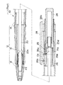
以下、図面を用いて本発明の実施の形態を説明する。図1及び図2は、本発明に係るノック式筆記具の第1実施形態を表す縦断面図である。図示のものは、筆記具としてボールペンに適用した例であり、筆記媒体はインキを収容したレフィールとなっている。
【0020】
このノック式筆記具10は、後筒14、後筒14の先端に螺着される先筒16及び先筒16の先端に螺着される先具18とからなる外筒12を備えており、外筒12内には、筆記媒体としてのレフィール20が軸線方向に移動可能に挿入収納されている。先具18の内部に形成された段部18aとレフィール20に形成されたバネ受け20aとの間に弾性体であるバネ22が介挿されており、バネ22はレフィール20を常時、後方へ付勢している。
【0021】
レフィール20の後端は係合体26に挿入されており、レフィール20と共に係合体26が外筒12内を移動するようになっている。係合体26の周面には、図3に示すように外径方向に突出した係止突起26aが形成されると共に、係止突起26aの3方を取り囲むようにしてスリットであるU字状孔26bが形成されている。このU字状孔26bによって係止突起26aは、径方向内方に撓むことができるようになっている。また、係止突起26aの頂部は、前方に向かうに連れて漸次高さが低くなるよう形成された傾斜面26cとなっている。
【0022】
係合体26の後端は、ノックバー25の中に摺動可能に挿入される。ノックバー25には、その先端に前記係合体26の係止突起26aに当接可能なカム部25aが形成されている。カム部25aは、先端に向かって鋭利な形状となっており、その両側面は第1カム面25bと第2カム面25cとなっている。また、ノックバー25の外周面には、軸線方向に伸びる縦溝25dが複数形成されており、対応する後筒14の内周面には、縦リブ14aが形成されており、縦溝25dと縦リブ14aとが嵌合することで、ノックバー25は外筒12に対して相対回転不能となっている。ノックバー25の後端部は一体的にノック体24となり、ノック体24は後筒14より後方に突出して外方に露出している。但し、ノック体24とノックバー25は、別体としてもよい。
【0023】
外筒12の外周後部には、クリップ28の基端28aが嵌着されている。クリップ28の反基端部の裏面には、外筒12の方へ突出する係止受け突部28bが形成されている。係止受け突部28bの後部には、図4(a)に示すように、後方に向かうに連れて漸次高さが低くなるよう傾斜した傾斜面28cが形成される。また、係止受け突部28bの前端側には、図4(b)に示したように、前方に向かうに連れて漸次幅が狭くなるよう傾斜したカム面28dが形成されると共に、前方に向けて開口し前記係止突起26aを収容可能な係止受部28eがカム面28dの後端に連設されている。
【0024】
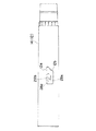
外筒12(後筒14)の外周面には、係止受け突部28bに対応して案内孔12aが形成されている。図5に示すように、案内孔12aは、係止受け突部28b(仮想線で示す)に対して横方向片側だけが係止受け突部28bよりも幅広くなっている。案内孔12aの後端には、後方に向かうに連れて漸次、係止受け突部28bの在る側に向かうカム面12bが形成されている。
【0025】
この案内孔12aを係合体26の係止突起26aが貫通している。また、前記ノックバー25のカム部25aの先端は、係止受部28eとカム面28dとの境目付近を通過する軸線方向線上にくるように設定されており(図6参照)、その境目よりカム面28d側に第1カム面25bが、係止受部28e側に第2カム面25cが配置されている。
【0026】
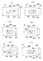
以上のように構成されるノック式筆記具の作用を図6を参照しながら以下に説明する。
【0027】
非使用時、レフィール20は、バネ22によって後方へ付勢されて、外筒12内に完全に収納された退没位置にある。このとき、係合体26の係止突起26aは案内孔12aのカム面12bの最後端で案内孔12aに当接しており(図6(a))、係合体26及びレフィール20がこれ以上後方へ後退するのを阻止している。
【0028】
次に、レフィール20を使用するため、使用者がノック体24を前方に向けてノックすると、ノックバー25のカム部25aの第1カム面25bが係止突起26aに当接して係止突起26aを前方へ押し出す(図6(b))。係止突起26aはクリップ28の係止受け突部28bに干渉するが、係止受け突部28bの傾斜面28cと係止突起26aの傾斜面26cとが摺接し、係止突起26aはその撓み性を利用して、傾斜面28cに沿って外筒12内へと潜り込むので、係止受け突部28bを通過することができる。第1カム面25bにより係止突起26aは、横方向にそれて係止受け突部28bから逃げるようなことがなく、軸線方向まっすぐに前進し、係止受け突部28bを通過する。
【0029】
係止突起26aは係止受け突部28bを通過した後、案内孔12aの前端まで到達する(図6(c))。
【0030】
次いで、使用者がノック体24への力の付加を緩めると、バネ22によりレフィール20及び係合体26が後方へ移動する。係止突起26aは、ノックバー25のカム部25aの第1カム面25bに誘導されて、横方向にそれることなく、軸線方向にまっすぐに後退し、係止受け突部28bのカム面28dに当接した後、これを摺接し、係止受部28eへと到達して、係止受部28eと係合する(図6(d))。これにより、レフィール20はその後退移動が禁止され、レフィール20の先端が外筒12の先端より突出した前進位置に保持されるので、使用に供されることになる。
【0031】
使用が終了し、再び使用者がノック体24をノックすると、ノックバー25のカム部25aの第2カム面25cが係止突起26aに当接して、係止突起26aを前方へ押し出す。これにより、係止突起26aは、係止受部28eから離脱し、ノックバー25のカム部25aの第2カム面25cを摺接し、係止受け突部28bの在る側と横方向反対側へと移動する(図6(e))。そして、使用者がノック体24への力の付加を止めると、係止突起26aは係止受け突部28bの傍らを通って後退し、カム面12bに当接した後、カム面12bを摺接してその最後端の位置に戻る。これによりレフィール20は退没位置に戻り外筒12内に収納される(図6(f))。
【0032】
クリップ28の基端28aは外筒12に固定されているため、ノック体24のノックと共にクリップ28が移動することはなく、クリップ28を握っていてもノック体24のノック操作はできるため、操作性の良いものとなっている。また、レフィール20を退没位置に戻すときも、ノック体24のノックで行うことができ、即ち、前進位置と退没位置との切換をノック体24のノックだけで行うことができるため、操作性が良い。
【0033】
また、ノック体24に力を加える前進時には、係合体26の係止突起26aに強制的にクリップ28の係止受け突部28bの下をくぐらせているため、その際の抵抗が操作者に節度感を与えることになる。その一方で、後退時のノック体24に力を加えない時には、係止突起26aにクリップ28の係止受け突部28bの傍らを移動させるようにしたので、係止突起26aが途中で引っかかることなく動作が円滑に行われることとなる。
【0034】
使用者がレフィール20を収納し忘れてレフィール20が前進位置にある状態で、筆記具をポケット等に入れようとして、クリップ28の反基端部を外筒12から遠ざかる方向に動かすと、係止受部28eと係止突起26aとの係合が解除されるので、レフィール20は、自動的にバネ22の付勢力で後方へ移動し退没位置に戻る。従って、インキでポケットを汚すことを防止することができる。
【0035】
外筒12の案内孔12aから外径方向に突出する係止突起26aは、径方向内方に撓むことができるため、組み立てる際も、この撓み性を利用して、後筒14の前方から係合体26を押し入れることで、後筒14内に組み付けることができる。
【0036】
次に、図7ないし図12は、本発明の第2実施形態を表す図である。
【0037】
このノック式筆記具30は、後筒34、後筒34の先端に螺着される先筒36及び先筒36の先端に螺着される先具38とからなる外筒32を備えており、外筒32内には、筆記媒体としてのレフィール40が軸線方向に移動可能に挿入収納されている。先具38の内部に形成された段部38aとレフィール40に形成されたバネ受け40aとの間に弾性体であるバネ42が介挿されており、バネ42はレフィール40を常時、後方へ付勢している。
【0038】
レフィール40の後端は係合体46に挿入されており、レフィール40と共に係合体46が外筒32内を移動するようになっている。係合体46の周面には、図9に示すように外径方向に突出した係止突起46aが形成されると共に、係止突起46aの3方を取り囲むようにしてスリットであるU字状孔46bが形成されている。このU字状孔46bによって係止突起46aは、径方向内方に撓むことができるようになっている。また、係合体46の係止突起46aよりも後方で、且つ周方向から見て係止突起46aから略±90度離れた位置に、後述のノックバー45のカム部45aに係合するカム受部46dが形成されている。カム受部46dは、それぞれ傾斜面となった第1カム面46d1及び第2カム面46d2と、これらの第1カム面46d1と第2カム面46d2の交差点に形成された凹部46d3とを有している。
【0039】
係合体46の後端は、ノックバー45の中に摺動可能に挿入される。ノックバー45には、図10に詳細に示したように、その先端に前記係合体46のカム受部46dに係合するカム部45aが形成されている。カム部45aは、それぞれ傾斜面となった第1カム面45a1と第2カム面45a2と、第1カム面45a1と第2カム面45a2の交差点にあって、先端に向かって鋭利な形状となった頂部45a3と、を有している。また、ノックバー45の外周面には、軸線方向に伸びる縦リブ45dが複数形成されており、対応する後筒34の内周面には、縦溝34aが形成されており、縦リブ45dと縦溝34aとが嵌合することで、ノックバー45は外筒32に対して相対回転不能となっている。
【0040】
ノックバー45の後端はノック体44内に圧入されて、ノックバー45とノック体44とが一体的になっており、ノック体44は後筒34より後方に突出して外方に露出している。ノック体44と係合体46との間には、両者を軸方向に離間する方向に付勢するバネ47が介挿されている。
【0041】
外筒32の外周後部には、クリップ48の基端48aが嵌着されている。クリップ48は、第1実施形態のように一体品であっても良いが、この実施形態では、金属製のクリップ本体49と、クリップ本体49の反基端部に取り付けられたプラスチック製のクリップ飾り50とからなっている。クリップ飾り50の裏面には、外筒32の方へ突出する係止受け突部48bが形成されている。係止受け突部48bの後部には、後方に向かうに連れて漸次高さが低くなるよう傾斜した傾斜面48c(図8)が形成される。また、係止受け突部48bの前端側には、図11に示したように、前方に向かうに連れて漸次幅が狭くなるよう傾斜したカム面48dが形成されると共に、前方に向けて開口し前記係止突起46aを収容可能な係止受部48eがカム面48dの後端に連設されている。また、クリップ飾り50の裏面の両側部には、図11に示したように、クリップ本体49の突部49aを受けるための凹部50aが形成される。
【0042】
外筒32(後筒34)の外周面には、係止受け突部48bに対応して案内孔32aが形成されている。図7の点線で示すように、案内孔32aは、係止受け突部48b(仮想線で示す)に対して横方向片側だけが係止受け突部48bよりも幅広くなっている。案内孔32aの後端には、後方に向かうに連れて漸次、係止受け突部48bの在る側に向かうカム面32bが形成されている。
【0043】
この案内孔32aを係合体46の係止突起46aが貫通している。また、前記ノックバー45のカム部45aの頂部45a3は、図8に示したように、レフィール40が外筒32内の退没位置にあるときに、凹部46d3と軸線方向同一線上になるように設定されている。
【0044】
以上のように構成されるノック式筆記具の作用を図12を参照しながら以下に説明する。
【0045】
非使用時、レフィール40は、バネ42によって後方へ付勢されて、外筒32内に完全に収納された退没位置にある。このとき、係合体46の係止突起46aは案内孔32aのカム面32bの最後端で案内孔32aに当接しており(図12(a))、係合体46及びレフィール40がこれ以上後方へ後退するのを阻止している。
【0046】
次に、レフィール40を使用するため、使用者がノック体44を前方に向けてノックすると、ノックバー45のカム部45aの頂部45a3が、係合体46のカム受部46dの凹部46d3に係合して、係合体46を前方へ押し出す(図12(b))。係合体46の係止突起46aはクリップ48の係止受け突部48bに干渉するが、係止受け突部48bの傾斜面48cに摺接し、係止突起46aはその撓み性を利用して、傾斜面48cに沿って外筒32内へと潜り込むので、係止受け突部48bを通過することができる。カム部45aの頂部45a3がカム受部46dの凹部46d3に係合しているので、係止突起46aは、横方向にそれて係止受け突部48bから逃げるようなことがなく、軸線方向にまっすぐに前進し、係止受け突部48bを通過する。
【0047】
係止突起46aは係止受け突部48bを通過した後、案内孔32aの前端まで到達する(図12(c))。
【0048】
次いで、使用者がノック体44への力の付加を緩めると、バネ42によりレフィール40及び係合体46が後方へ移動する。係止突起46aは、ノックバー45のカム部45aの頂部45a3が凹部46d3に係合したままで、横方向にそれることなく、軸線方向にまっすぐに後退し、係止受け突部48bのカム面48dに当接する。さらにノック体44の力の付加を緩めると、係合体46の凹部46d3とカム部45aの頂部45a3との係合が外れ、係止突起46aは、カム面48dを摺接し、係止受部48eへと到達して、係止受部48eと係合する(図12(d))。これにより、レフィール40はその後退移動が禁止され、レフィール40の先端が外筒32の先端より突出した前進位置に保持されるので、使用に供されることになる。ノック体44はバネ47の付勢力によって後方位置に戻る。
【0049】
使用が終了し、再び使用者がノック体44をノックすると、ノックバー45のカム部45aの第1カム面45a1が係合体46のカム受部46dの第1カム面46d1に当接して、係合体46を前方へ押し出す。これにより、係合体46の係止突起46aは、係止受部48eから離脱し、係止受け突部48bの在る側と横方向反対側へと移動する(図12(e))。そして、使用者がノック体44への力の付加を止めると、係止突起46aは係止受け突部48bの傍らを通って後退し、カム面32bに当接した後、カム面32bを摺接してその最後端の位置に戻る(図12(f))。これによりレフィール40は退没位置に戻り外筒32内に収納される。
【0050】
以上により、第1実施形態と同様の効果が得られる。また、この実施形態では、係止突起46aとは別にカム受部46dが形成されているため、安定してノックバー45のカム部45aによる係合体46の誘導動作を行わせることができる。
【0051】
次に、図13及び図14は、本発明の第3実施形態を表す図である。
【0052】
上記第1及び第2実施形態では、ノック体24、44が外筒12、32の後端から突出する後端ノック式の筆記具について説明したが、本実施形態では、外筒の側部にノック体(径方向にノックするものでも、軸線方向にスライドノックするものでもよい)を備える所謂、サイドノック式の筆記具となっている点で前実施形態と異なっている。
【0053】
このサイドノック式筆記具60は、後筒34の先端に螺着される先筒66及び先筒66の先端に螺着される先具68とからなる外筒62を備えており、外筒62内には、筆記媒体としてのレフィール70が軸線方向に移動可能に挿入収納されている。先筒66の内部に形成された段部66aとレフィール受け71の前端との間に弾性体であるバネ72が介挿されている。レフィール受け71内にはレフィール70の後端が挿入されており、レフィール受け71とレフィール70は一体的になっている。そして、バネ72はレフィール70及びレフィール受け71を常時、後方へ付勢している。
【0054】
レフィール受け71の前部には、拡径されると共にその後端面がカム面となったノック受部71aが形成されている。また、先筒66には、先筒66の周面に揺動可能となったノック体74が取り付けられている。ノック体74がサイドノックされ、先筒66内部へと揺動されると、ノック受部71aのカム面が前方へと押し出されるようになっている。
【0055】
レフィール受け71の後端部には、係合体76が当接しており、係合体76の位置によってレフィール受け71及びレフィール70の位置決めを行うことができるようになっている。係合体76の周面には、図14に拡大して示すように、第2実施形態の係止突起46a、U字状孔46b及びカム受部46dと同じ係止突起76a、U字状孔76b及びカム受部76dが形成されており、係止突起76aは、径方向内方に撓むことができるようになっている。カム受部76dが、それぞれ傾斜面となった第1カム面76d1及び第2カム面76d2と、これらの第1カム面76d1と第2カム面76d2の交差点に形成された凹部76d3とを有しているのも第2実施形態と同じである。
【0056】
レフィール受け71の後端は、ノックバー75に連結される。ノックバー75には、第2実施形態のノックバー45のカム部45aと同じように前記係合体76のカム受部76dに係合するカム部75aが形成されており、カム部75aは、それぞれ傾斜面となった第1カム面75a1と第2カム面75a2と、第1カム面75a1と第2カム面75a2の交差点にあって、先端に向かって鋭利な形状となった頂部75a3と、を有している。また、ノックバー75の外周面には、軸線方向に伸びる縦リブ75dが複数形成されており、対応する後筒34の縦溝34aに縦リブ75dが嵌合することで、ノックバー75は外筒62に対して相対回転不能となっている。
【0057】
係合体76の内周面側には、バネ77が設けられており、このバネ77は係合体76とレフィール受け71との間に介挿されて、係合体76をレフィール受け71に対して後方に付勢して、言い換えれば、ノックバー75の方に向かって付勢しており、さらに言い換えれば、係合体76のカム受部76dをカム部75aに向かって当接させるように付勢する役割をするものである。バネ77は、バネ72よりはバネ力の弱いものが選定される。
【0058】
外筒62の後端には、後端キャップ78が取り付けられる。また、外筒62の外周後部には、クリップ48が嵌着される。クリップ48は、第2実施形態と同じものであるので、詳細説明を省略する。また、外筒62の外周面の案内孔62aも第2実施形態と同じである。
【0059】
以上のように構成されるサイドノック式筆記具の作用は、第2実施形態と同様に行われる。すなわち、レフィール70を前進させるため、使用者がノック体74をノックすると、ノック体74がレフィール受け71を前進させ、レフィール受け71に連結されたノックバー75が前進し、ノックバー75のカム部75aと、係合体76のカム受部76dとが図12(a)〜図12(d)と同じ動作を行う。こうして、係合体76の係止突起76aが、係止受部48eと係合し、係合体76によってレフィール70はその後退移動が禁止され、レフィール70の先端が外筒62の先端より突出した前進位置に保持される。
【0060】
使用が終了し、再び使用者がノック体74をノックすると、ノック体74がレフィール受け71を前進させ、レフィール受け71に連結されたノックバー75が前進し、ノックバー75のカム部75aと、係合体76のカム受部76dとが図12(e)〜図12(f)と同じ動作を行う。こうして、レフィール70の先端が外筒62の先端より退没位置に戻り、外筒62内に収納される。以上により、前実施形態と同様の効果が得られる。
【0061】
次に、図15ないし図17は、本発明の第4実施形態を表す図である。図において、前実施形態と同一の部材は同一の符号を付し、その詳細説明を省略する。この実施形態では、サイドノック式の筆記具であり、第3実施形態に比べて部品点数を削減している点で異なっている。
【0062】
すなわち、この実施形態のノック式筆記具80の係合体86は、図17に示したように、係止突起86a及びU字状孔86bを有しており、係止突起86aと周方向に180度離れたところは、スリット86cとなっている。そして、この係合体86は、スリット86cを利用してレフィール受け81の後端にはめ合わされており、レフィール70の後端を支持するレフィール受け81と一体的に外筒82内を移動することができるようになっている。ノックバー75やバネ77は省略することができる。
【0063】
また、外筒82の案内孔82aは、図16に示したように、係止受け突部48b(仮想線で示す)に対して横方向片側だけが係止受け突部48bよりも幅広くなっている。案内孔82aの後端には、後方に向かうに連れて漸次、係止受け突部48bの在る側に向かう後端カム面82bが形成されている。また、案内孔82aの前端には、前方に向かうに連れて漸次、係止受け突部48bの無い側に向かう前端第1カム面82c及び前端第1カム面82cと連設される前端第2カム面82dが形成されている。
【0064】
以上のように構成されるサイドノック式筆記具において、レフィール70を前進させるため、使用者がノック体74をノックすると、ノック体74がレフィール受け81を前進させ、レフィール受け81の後端に連結された係合体86が前進する。これにより、図12(a)〜図12(d)の左半分で示したものと同様の、係合体86の係止突起86aと係止受け突部48bの協働動作がなされて、図16の矢印で示したように、係止突起86aが移動し、係止突起86aが係止受部48eと係合する。こうして、レフィール70の先端が外筒82の先端より突出した前進位置に保持される。
【0065】
使用が終了し、再び使用者がノック体74をノックすると、ノック体74がレフィール受け71を前進させ、レフィール受け71に連結された係合体86が前進する。これにより、係合体86の係止突起86aは、図16の矢印で示したように、係止受部48eを離脱し、前端第2カム面82dに到達し、前端第2カム面82dを摺接し、係止受け突部48bの在る側と横方向反対側へと移動する。そして、使用者がノック体74への力の付加を止めると、係止突起86aは係止受け突部48bの傍らを通って後退し、後端カム面82bに当接した後、後端カム面82bを摺接してその最後端の位置に戻る。これによりレフィール70は退没位置に戻り、外筒82内に収納される。
【0066】
この後退動作が確実に行われるために、前端第1カム面82c及び前端第2カム面82dの境目は、係止受部48eに対向する部分よりも係止受け突部48b側寄りになるように形成されている。
【0067】
以上のように、この第4実施形態によれば、上記実施形態の効果に加えて、部品点数が少なくて構造を簡単にすることができる。
【0068】
尚、上記例では、筆記具としてボールペンに適用した例を示したが、これに限るものではなく、シャープペンシルにおいても、筆記媒体として芯送り出し機構とすれば、ノック体の操作で芯送り出し機構を退没位置から前進位置まで移動させることができるので、同様に適用することができる。また、マーカペンにおいても、筆記媒体としてインキまたはフェルト芯を含みこれらを保持する保持体とすれば、同様に適用することができる。
【0069】
さらに、上記実施形態では、係合体とレフィール、レフィール受けとが別部品であったが、これに限るものではなく、筆記媒体、係合体等を一体に形成することも可能である。
【0070】
【発明の効果】
以上説明したように、請求項1ないし6記載の発明によれば、クリップの基端が外筒に固定されているため、ノック体のノックと共にクリップが移動することはなく、クリップを握っていてもノック体のノック操作ができるので、操作性が向上する。また、通常のノック式筆記具と同様に、ノック体のノックだけで筆記媒体の前進位置、退没位置との切換ができるので操作性が良好である。その上で、筆記媒体が前進位置にある状態で、ポケットに筆記具を収納しようとした場合には、クリップの反基端部を動かすと同時に、係止突起と係止受部との係合が解除されるため、筆記媒体は退没位置に戻ることができる。従って、筆記媒体によりポケットが汚れたり損傷したりすることを防止することができる。
【図面の簡単な説明】
【図1】本発明に係るノック式筆記具の第1実施形態を表す縦断面図であり、レフィール(筆記媒体)が前進位置にある状態を示す。
【図2】本発明に係るノック式筆記具の第1実施形態を表す縦断面図であり、レフィール(筆記媒体)が退没位置にある状態を示す。
【図3】第1実施形態のノック体と係合体とを表す図であり、(a)は断面図、(b)は平面図、(c)は側面図である。
【図4】第1実施形態のクリップを示す図であり(a)は側面図、(b)は底面図及び(c)は(a)の矢視図である。
【図5】第1実施形態の外筒(後筒)の平面図である。
【図6】(a)ないし(f)は、第1実施形態の外筒の案内孔と係止突起との動作を表す説明図である。
【図7】本発明に係るノック式筆記具の第2実施形態の平面図である。
【図8】本発明に係るノック式筆記具の図7の8−8線に沿ってみた図である。
【図9】第2実施形態の係合体の(a)は側面図、(b)は平面図、(c)は(b)図の9c−9c線に沿って見た断面図である。
【図10】第2実施形態のノックバーの(a)は側面図、(b)は平面図、(c)は(b)図の10c−10c線に沿って見た断面図である。
【図11】第2実施形態のクリップの裏面を表す図である。
【図12】(a)ないし(f)は、第2実施形態の外筒の案内孔と係止突起との動作(左側)、及びカム受部とカム部(右側)の動作を表す説明図である。
【図13】本発明に係るノック式筆記具の第3実施形態を表す縦断面図である。
【図14】図13の後部部分拡大図である。
【図15】本発明に係るノック式筆記具の第4実施形態を表す縦断面図である。
【図16】第4実施形態の外筒の案内孔を表す図である。
【図17】第4実施形態の係合体を表す斜視図である。
【符号の説明】
10,30,60,80 ノック式筆記具
12,32,62,82 外筒
12a,32a,62a,82a 案内孔
12b,32b カム面
20,40,70 レフィール(筆記媒体)
22,42,72 バネ(弾性体)
24,44,74 ノック体
25,45,75 ノックバー
25a,75a カム部
25b 第1カム面
25c 第2カム面
26,46,76,86 係合体
26a,46a,76a,86a 係止突起
26c 傾斜面
28,48 クリップ
28a,48a 基端
28b,48b 係止受け突部
28c,48c 傾斜面
28e,48e 係止受部
46d,76d カム受部
82d 前端カム面[0001]
BACKGROUND OF THE INVENTION
The present invention relates to a knock-type writing instrument that moves a writing medium such as a ballpoint pen, a mechanical pencil, or a marker to a forward position where the tip of the writing medium protrudes from the tip of an outer cylinder by knocking.
[0002]
[Prior art]
Conventionally, this type of knock-type writing instrument has an outer cylinder, a writing medium inserted and accommodated in the outer cylinder so as to be movable in the axial direction, an elastic body that urges the writing medium backward, and a base end of the outer cylinder. A fixed clip and a knock body exposed outward from the outer cylinder in order to be knocked.From the retracted position where the writing medium has retracted into the outer cylinder by the operation of the knock body, The writing medium is moved to a forward position where the tip of the writing medium protrudes from the tip of the outer cylinder.
[0003]
[Problems to be solved by the invention]
However, with such conventional knock-type writing instruments, if you forget to retract the writing medium and insert a clip into the edge of the pocket of the clothes and store it in the pocket, the writing medium will contaminate the pocket or make a hole. There is a problem that there is something to do.
[0004]
As a knock type writing instrument in which such a problem is solved, there are those described in Japanese Utility Model Publication No. 5-25915 or Japanese Utility Model Publication No. 6-15735 filed by the present applicant. In the knock type writing instruments disclosed in these publications, the clip is integrated with a knock body protruding from the rear end of the outer cylinder, and a locking projection is provided on the back surface of the tip of the clip. The writing medium is held at the forward position by engaging with a latch receiving portion formed on the outer cylinder. In this knock type writing instrument, when the tip of the clip is moved away from the outer cylinder in order to insert the clip into the pocket, the engagement between the locking projection and the locking receiving portion is released, so that the writing medium is automatically retracted. , Can prevent pocket dirt and damage. However, since the clip moves together with knocking the knock body, there is a problem that it is difficult to knock if the clip is held, and it is difficult to knock, and to return to the retracted position Because both ends of the clip must be swung up and down and knocking cannot be returned to the stowed position, the operation for moving forward and the operation for retracting are different, making it difficult to operate There is.
[0005]
The present invention has been made in view of such problems, and the inventions according to claims 1 to 6 have good knock operability and automatically put the writing medium in the retracted position when using the clip. The object is to provide a knockable writing instrument that can be returned.
[0006]
[Means for Solving the Problems]
In order to achieve the above object, the invention according to claim 1 of the present invention includes an outer cylinder, a writing medium inserted and accommodated in the outer cylinder so as to be movable in the axial direction, and an elastic force for biasing the writing medium backward. And a knock body exposed outward from the outer cylinder to be knocked, and the retracted position where the writing medium is retracted into the outer cylinder by the operation of the knock body and the tip of the writing medium are outside. In the knock-type writing instrument that transitions between the forward position protruding from the tip of the cylinder,
An engaging body for positioning the writing medium is provided in the outer cylinder, a locking projection is formed on the engaging body, and on the back surface of the opposite base end portion of the clip whose base end is fixed to the outer cylinder, A lock receiving protrusion having a lock receiving portion is formed on the front end side, and a guide hole is formed in the outer cylinder corresponding to the lock receiving protrusion, and the guide hole is formed in the lock receiving protrusion. On the other hand, only one side in the lateral direction is wider than the latch receiving projection, And at the rear end, as it goes rearward, a cam surface toward the side where the locking receiving projection is located is formed, The writing projection is engaged with the latch receiving portion through the guide hole, so that the writing medium is held at the forward position, while the locking projection is disengaged from the latch receiving portion. The writing medium is held in the retracted position by being positioned backward,
A knock bar that is integral with the knock body or moves forward by operation of the knock body is provided in the outer cylinder, and a cam portion that can be engaged with the engagement body is formed on the knock bar. The projection is guided from behind the latch receiving projection to the latch receiving portion from behind the latch receiving projection, and the latch projection is guided from the latch receiving portion to avoid the latch receiving projection. Through one side Make sliding contact with the cam surface of the guide hole, It is characterized in that it is guided further backward than the locking receiving projection.
[0007]
By operating the knock body, the cam portion of the knock bar that is integral with the knock body or advanced with the operation of the knock body is engaged with the engagement body, and the locking projection is moved forward against the urging force of the elastic body. Press. The cam part of the knock bar moves the locking projection from behind the locking receiving protrusion of the clip to the locking receiving part provided on the front end side of the locking receiving protrusion. Let Thus, the locking projection engages with the locking receiving portion, and the writing medium is held at the advanced position in which the leading end protrudes from the leading end of the outer cylinder. You can write in this state.
[0008]
By operating the knock body again, the cam portion of the knock bar is brought into contact with the locking projection, and the locking projection is avoided from the locking receiving portion by the urging force of the cam portion and the elastic body. Then, it is moved to the rear of the latch receiving projection. In this way, the locking projection is disengaged from the locking receiving portion, is positioned behind the locking receiving projection, and is held at the retracted position where the writing medium has retracted into the outer cylinder.
[0009]
According to a second aspect of the present invention, in the first aspect, the cam portion of the knock bar is engageable with the locking protrusion of the engaging body, and the locking protrusion is locked. A first cam surface that guides from behind the receiving protrusion to the engaging receiving part through the engaging receiving protrusion, and the engaging protrusion from the engaging receiving part to avoid the engaging receiving protrusion from one side in the lateral direction And a second cam surface that guides to the rear of the latch receiving projection.
[0010]
Since the locking projection is reliably guided along the predetermined route by the first cam surface and the second cam surface of the cam portion of the knock bar, no malfunction occurs.
[0011]
According to a third aspect of the present invention, in the first aspect of the present invention, the engagement body includes a cam receiving portion that engages with the cam portion of the knock bar, in addition to the locking protrusion. To do.
[0012]
Since the cam receiving portion is formed in the engaging body separately from the locking projection, the guiding operation of the engaging body by the cam portion of the knock bar can be performed stably.
[0013]
According to a fourth aspect of the present invention, there are provided an outer cylinder, a writing medium inserted and accommodated in the outer cylinder so as to be movable in the axial direction, an elastic body for urging the writing medium backward, and an outer cylinder for knocking operation. A knock body exposed outward from the side surface, and the operation of the knock body causes the writing medium to move forward, the retracted position where the writing medium retracts into the outer cylinder, and the tip of the writing medium is the tip of the outer cylinder In the knock-type writing instrument that transitions between more advanced forward positions,
An engaging body that is connected to the writing medium and positions the writing medium is provided in the outer cylinder, and a locking projection is formed on the engaging body, and the base end of the clip whose base end is fixed to the outer cylinder A locking receiving projection having a locking receiving portion on the front end side is formed on the back surface of the portion, a guide hole is formed in the outer cylinder corresponding to the locking receiving projection, Only one side in the lateral direction with respect to the locking receiving projection is wider than the locking receiving projection, further In the guide hole, a front end cam surface is formed at the front end portion facing the locking receiving portion, gradually toward the front side, as it goes forward. In addition, a rear end cam surface is formed at the rear end portion gradually toward the rear side toward the side where the locking receiving protrusion is located. And
The writing projection is engaged with the latch receiving portion through the guide hole, so that the writing medium is held at the forward position, while the locking projection is disengaged from the latch receiving portion. The writing medium is held in the retracted position by being positioned backward,
By performing a knocking operation of the knock body to advance the writing medium in the retracted position, the locking projection is moved from behind the locking receiving projection to the locking receiving portion from behind the locking receiving projection. And moving the writing medium in the forward position by moving the knocking body to move the locking projection from the locking receiving portion to the front end cam surface so that the locking receiving protruding portion is moved. Avoid one side in the horizontal direction Slide it against the rear cam surface, It moves to the back rather than a latching receiving protrusion.
[0014]
By operating the knock body to advance the writing medium in the retracted position against the urging force of the elastic body, the engaging protrusion of the clip connected to the engaging protrusion of the engaging body connected to the writing medium. It is moved from behind to the latch receiving projection provided on the front end side of the latch receiving projection. Thus, the locking projection engages with the locking receiving portion, and the writing medium is held at the advanced position in which the leading end protrudes from the leading end of the outer cylinder. You can write in this state.
[0015]
By operating the knock body to advance the writing medium in the forward movement position, the locking receiving portion is slidably brought into contact with the front end cam surface to avoid the locking receiving projection and to the rear of the locking receiving projection. Move. In this way, the locking projection is disengaged from the locking receiving portion, is positioned behind the locking receiving projection, and is held at the retracted position where the writing medium has retracted into the outer cylinder.
[0016]
According to a fifth aspect of the present invention, in any one of the first to fourth aspects, the engagement body is formed with a slit for bending the locking projection in the inner diameter direction. And
[0017]
The locking protrusion is the clip's locking receiving protrusion. Part When it interferes with the Part By passing through, the catching catch Part Can move forward. Further, when the operator feels the resistance at this time through the knocking body, a sense of moderation can be obtained and operability can be improved.
[0018]
The invention according to claim 6 is the one according to claim 5, wherein an inclined surface (28c) inclined so as to gradually decrease in height toward the rear is formed at the rear portion of the locking receiving projection. An inclined surface (26c) is formed at the top of the locking projection so as to gradually decrease in height toward the front.
The locking protrusion is the clip's locking receiving protrusion. Part When the interference is caused, the inclined surface of the locking receiving projection and the inclined surface of the locking projection come into sliding contact, so that the locking projection can smoothly cross the locking receiving projection.
[0019]
DETAILED DESCRIPTION OF THE INVENTION
Hereinafter, embodiments of the present invention will be described with reference to the drawings. FIG.1 and FIG.2 is a longitudinal cross-sectional view showing 1st Embodiment of the knock type writing instrument which concerns on this invention. The illustrated one is an example applied to a ballpoint pen as a writing instrument, and the writing medium is a refill containing ink.
[0020]
The knocking
[0021]
The rear end of the
[0022]
The rear end of the
[0023]
A
[0024]
A
[0025]
The locking projection 26a of the engaging
[0026]
The operation of the knock-type writing instrument configured as described above will be described below with reference to FIG.
[0027]
When not in use, the
[0028]
Next, since the
[0029]
The locking projection 26a reaches the front end of the
[0030]
Next, when the user loosens the application of force to the
[0031]
When the use is finished and the user knocks the
[0032]
Since the
[0033]
Further, when the force applied to the knocking
[0034]
If the user forgets to store the
[0035]
Since the locking projection 26a that protrudes in the outer diameter direction from the
[0036]
Next, FIGS. 7 to 12 are views showing a second embodiment of the present invention.
[0037]
This knock-
[0038]
The rear end of the refill 40 is inserted into the engaging
[0039]
The rear end of the
[0040]
The rear end of the
[0041]
A
[0042]
A
[0043]
The locking
[0044]
The operation of the knock-type writing instrument configured as described above will be described below with reference to FIG.
[0045]
When not in use, the refill 40 is urged rearward by a
[0046]
Next, in order to use the refill 40, when the user knocks the
[0047]
The locking
[0048]
Next, when the user loosens the application of force to the
[0049]
When the use is finished and the user knocks the
[0050]
As described above, the same effect as in the first embodiment can be obtained. In this embodiment, since the
[0051]
Next, FIG.13 and FIG.14 is a figure showing 3rd Embodiment of this invention.
[0052]
In the first and second embodiments described above, the rear end knock type writing instrument in which the
[0053]
The side knock
[0054]
At the front part of the
[0055]
An
[0056]
The rear end of the
[0057]
A
[0058]
A
[0059]
The operation of the side knock type writing instrument configured as described above is performed in the same manner as in the second embodiment. That is, in order to advance the
[0060]
When the use is finished and the user knocks the
[0061]
Next, FIGS. 15 to 17 are views showing a fourth embodiment of the present invention. In the figure, the same members as those of the previous embodiment are denoted by the same reference numerals, and detailed description thereof is omitted. In this embodiment, it is a side knock type writing instrument, and is different in that the number of parts is reduced as compared with the third embodiment.
[0062]
That is, as shown in FIG. 17, the engaging
[0063]
Further, as shown in FIG. 16, the guide hole 82a of the
[0064]
In the side knock type writing instrument configured as described above, when the user knocks the
[0065]
When the use is finished and the user knocks the
[0066]
In order to ensure that the backward movement is performed, the boundary between the front end
[0067]
As described above, according to the fourth embodiment, in addition to the effects of the above embodiment, the number of parts can be reduced and the structure can be simplified.
[0068]
In the above example, an example in which the writing instrument is applied to a ballpoint pen is shown. However, the present invention is not limited to this, and even in a mechanical pencil, if a lead feeding mechanism is used as a writing medium, the lead feeding mechanism is retracted by operating the knock body. Since it can be moved from the sink position to the forward position, it can be similarly applied. Also, the marker pen can be similarly applied if it is a holding body that contains ink or a felt core as a writing medium and holds them.
[0069]
Furthermore, in the above-described embodiment, the engaging body, the refill, and the refill receiver are separate parts. However, the present invention is not limited to this, and the writing medium, the engaging body, and the like can be integrally formed.
[0070]
【The invention's effect】
As described above, according to the first to sixth aspects of the invention, since the base end of the clip is fixed to the outer cylinder, the clip does not move together with the knock of the knock body, and the clip is gripped. Since the knock body can be knocked, the operability is improved. Further, like a normal knock type writing instrument, the operability is good because the writing medium can be switched between the forward position and the retracted position only by knocking the knock body. In addition, when an attempt is made to store the writing instrument in the pocket while the writing medium is in the advanced position, at the same time as the opposite base end of the clip is moved, the engagement between the locking protrusion and the locking receiving portion is performed. Since it is released, the writing medium can return to the retracted position. Therefore, it is possible to prevent the pocket from being stained or damaged by the writing medium.
[Brief description of the drawings]
FIG. 1 is a longitudinal sectional view showing a first embodiment of a knock type writing instrument according to the present invention, and shows a state in which a refill (writing medium) is in an advanced position.
FIG. 2 is a longitudinal sectional view showing a first embodiment of a knock type writing instrument according to the present invention, and shows a state in which a refill (writing medium) is in a retracted position.
3A and 3B are diagrams illustrating a knock body and an engagement body according to the first embodiment, in which FIG. 3A is a cross-sectional view, FIG. 3B is a plan view, and FIG. 3C is a side view.
4A is a side view, FIG. 4B is a bottom view, and FIG. 4C is an arrow view of FIG. 4A.
FIG. 5 is a plan view of the outer cylinder (rear cylinder) of the first embodiment.
FIGS. 6A to 6F are explanatory views showing the operation of the guide hole and the locking projection of the outer cylinder according to the first embodiment.
FIG. 7 is a plan view of a second embodiment of the knock-type writing instrument according to the present invention.
8 is a view of the knock-type writing instrument according to the present invention taken along line 8-8 in FIG.
9A is a side view, FIG. 9B is a plan view, and FIG. 9C is a cross-sectional view taken along the
10A is a side view, FIG. 10B is a plan view, and FIG. 10C is a cross-sectional view taken along the
FIG. 11 is a diagram illustrating a back surface of a clip according to a second embodiment.
FIGS. 12A to 12F are explanatory views showing the operation (left side) of the guide hole and the locking projection of the outer cylinder and the operation of the cam receiving portion and the cam portion (right side) of the second embodiment. It is.
FIG. 13 is a longitudinal sectional view showing a knock type writing instrument according to a third embodiment of the present invention.
14 is an enlarged view of the rear part of FIG. 13. FIG.
FIG. 15 is a longitudinal sectional view showing a knock type writing instrument according to a fourth embodiment of the present invention.
FIG. 16 is a diagram illustrating a guide hole of an outer cylinder according to a fourth embodiment.
FIG. 17 is a perspective view illustrating an engagement body according to a fourth embodiment.
[Explanation of symbols]
10, 30, 60, 80 Knock-type writing instrument
12, 32, 62, 82 outer cylinder
12a, 32a, 62a, 82a Guide hole
12b, 32b Cam surface
20, 40, 70 refill (writing medium)
22, 42, 72 Spring (elastic body)
24, 44, 74 Knock body
25, 45, 75 knock bar
25a, 75a Cam part
25b First cam surface
25c Second cam surface
26, 46, 76, 86 Engagement body
26a, 46a, 76a, 86a Locking protrusion
26c inclined surface
28,48 clips
28a, 48a
28b, 48b Locking projection
28c, 48c inclined surface
28e, 48e Locking receiving part
46d, 76d Cam receiving part
82d Front end cam surface
Claims (6)
外筒(12,32,62)内には筆記媒体(20,40,70)の位置決めを行う係合体(24,46,76)が設けられ、該係合体に係止突起(26a,46a,76a)が形成されると共に、外筒(12,32,62)に基端が固定されたクリップ(28,48)の反基端部の裏面には、前端側に係止受部(28e,48e)を備えた係止受け突部(28b,48b)が形成されており、係止受け突部に対応して外筒(12,32,62)には案内孔(12a,32a,62a)が形成されて、案内孔は係止受け突部(28b,48b)に対して横方向片側のみが係止受け突部よりも幅広くなっており、かつ後端には後方に向かうに連れて漸次、係止受け突部の在る側に向かうカム面(12b,32b)が形成され、この案内孔(12a,32a,62a)を通って係止突起(26a,46a,76a)が係止受部(28e,48e)に係合することにより筆記媒体(20,40,70)が前進位置に保持される一方、係止突起(26a,46a,76a)が係止受部(28e,48e)に非係合となり係止受け突部(28b,48b)よりも後方に位置することにより筆記媒体(20,40,70)が退没位置に保持され、
外筒(12,32,62)内にはノック体(24,44)と一体のまたはノック体(74)の操作により前進するノックバー(25,45,75)が設けられ、該ノックバーには係合体(26,46,76)と係合可能なカム部(25a,45a,75a)が形成されており、該カム部が、前記係止突起(26a,46a,76a)を、係止受け突部(28b,48b)よりも後方から係止受け突部を越して係止受部(28e,48e)まで誘導すると共に、前記係止突起(26a,46a,76a)を、係止受部(28e,48e)から係止受け突部(28b,48b)を回避させ横方向片側を通り案内孔(12a,32a,62a)のカム面(12b,32b)に摺接させて、係止受け突部よりも後方まで誘導することを特徴とするノック式筆記具。The outer cylinder (12, 32, 62, 82), the writing medium (20, 40, 70) inserted and accommodated in the outer cylinder so as to be movable in the axial direction, and the elastic body (22) for urging the writing medium backward , 42, 72) and a knock body (24, 44, 74) exposed outward from the outer cylinder to be knocked, and the writing medium is retracted into the outer cylinder by the operation of the knock body In the knock-type writing instrument that transitions between the retracted position and the forward position where the tip of the writing medium protrudes from the tip of the outer cylinder,
Engaging bodies (24, 46, 76) for positioning the writing medium (20, 40, 70) are provided in the outer cylinder (12, 32, 62), and locking protrusions (26a, 46a, 76a) is formed, and on the back surface of the opposite base end portion of the clip (28, 48) whose base end is fixed to the outer cylinder (12, 32, 62), the latch receiving portion (28e, 48e) is formed with locking receiving protrusions (28b, 48b), and the outer cylinders (12, 32, 62) correspond to the locking receiving protrusions in the guide holes (12a, 32a, 62a). The guide hole is wider on one side in the lateral direction than the latch receiving projection (28b, 48b) with respect to the latch receiving projection (28b, 48b), and gradually increases toward the rear at the rear end. A cam surface (12b, 32b) is formed toward the side where the locking receiving projection is located, and this guide hole (12a 32a, 62a) and the locking projections (26a, 46a, 76a) engage with the locking receiving portions (28e, 48e), whereby the writing medium (20, 40, 70) is held in the advanced position. The locking projections (26a, 46a, 76a) are disengaged from the locking receiving portions (28e, 48e), and are positioned rearward of the locking receiving projections (28b, 48b). 70) is held in the retracted position,
In the outer cylinder (12, 32, 62), there are provided knock bars (25, 45, 75) which are integral with the knock body (24, 44) or which are advanced by operation of the knock body (74). A cam portion (25a, 45a, 75a) that can be engaged with the united body (26, 46, 76) is formed, and the cam portion receives the locking projection (26a, 46a, 76a). From the rear of the portion (28b, 48b), it passes through the locking receiving projection to the locking receiving portion (28e, 48e), and the locking projection (26a, 46a, 76a) is moved to the locking receiving portion ( 28e, 48e) avoiding the latch receiving projections (28b, 48b), passing through one side in the lateral direction and slidingly contacting the cam surfaces (12b, 32b) of the guide holes (12a, 32a, 62a) A knot characterized by being guided backward from the Formula writing instruments.
外筒(82)内には筆記媒体(70)と連結されて筆記媒体の位置決めを行う係合体(86)が設けられ、該係合体に係止突起(86a)が形成されると共に、外筒(82)に基端が固定されたクリップ(48)の反基端部の裏面には、前端側に係止受部(48e)を備えた係止受け突部(48b)が形成されており、係止受け突部に対応して外筒(82)には案内孔(82a)が形成されて、案内孔は係止受け突部(48b)に対して横方向片側のみが係止受け突部よりも幅広くなっており、さらに案内孔(82a)には、係止受部(48e)と対向する前端部に、前方に向かうに連れて漸次、係止受け突部の無い側に向かう前端カム面(82d)が形成されると共に、後端部に、後方に向かうに連れて漸次、係止受け突部の在る側に向かう後端カム面(82b)が形成されており、
この案内孔(82a)を通って係止突起(86a)が係止受部(48e)に係合することにより筆記媒体(70)が前進位置に保持される一方、係止突起(86a)が係止受部(48e)に非係合となり係止受け突部(48b)よりも後方に位置することにより筆記媒体が退没位置に保持され、
ノック体(74)のノック操作を行って前記退没位置にある筆記媒体を前進させることにより、前記係止突起(86a)を、係止受け突部(48b)よりも後方から係止受け突部を越して係止受部(48e)まで移動させると共に、ノック体(74)のノック操作を行って前記前進位置にある筆記媒体(70)を前進させることにより、前記係止突起(86a)を、係止受部(48e)から前端カム面(82d)に摺接させて係止受け突部(48b)を回避させ横方向片側を通り後端カム面(82b)に摺接させて、係止受け突部(48b)よりも後方まで移動させることを特徴とするノック式筆記具。An outer cylinder (82), a writing medium (70) inserted and accommodated so as to be movable in the axial direction within the outer cylinder, an elastic body (72) for urging the writing medium rearward, and an outer cylinder to be knocked A knock body (74) exposed outward from the cylinder side surface, and the writing medium is advanced by the operation of the knock body, and the retracted position where the writing medium is retracted into the outer cylinder and the tip of the writing medium are In the knock-type writing instrument that transitions between the forward position protruding from the tip of the outer cylinder,
In the outer cylinder (82), there is provided an engaging body (86) which is connected to the writing medium (70) and positions the writing medium, and a locking projection (86a) is formed on the engaging body, and the outer cylinder On the back surface of the opposite base end portion of the clip (48) whose base end is fixed to (82), a locking receiving projection (48b) having a locking receiving portion (48e) is formed on the front end side. A guide hole (82a) is formed in the outer cylinder (82) corresponding to the latch receiving projection, and only one side of the guide hole in the lateral direction with respect to the latch receiving projection (48b) is the latch receiving projection. The guide hole (82a) has a front end that faces the engagement receiving portion (48e) and gradually advances toward the front side toward the side without the engagement receiving projection. A cam surface (82d) is formed, and gradually toward the rear end, toward the side where the locking receiving projection is located, as it goes rearward. Rear cam surface (82b) is formed,
The writing projection (86a) is held in the forward position by engaging the locking projection (86a) with the locking receiving portion (48e) through the guide hole (82a), while the locking projection (86a) The writing medium is held in the retracted position by being disengaged from the locking receiving portion (48e) and positioned behind the locking receiving projection (48b),
When the knocking body (74) is knocked to advance the writing medium in the retracted position, the locking protrusion (86a) is moved from behind the locking receiving protrusion (48b). The locking projection (86a) is moved by moving the writing medium (70) in the advanced position by moving the knocking body (74) by moving the knocking body (74). Is slidably brought into contact with the front end cam surface (82d) from the lock receiving portion (48e) to avoid the lock receiving projection (48b) and slidably contacted with the rear end cam surface (82b) through one side in the lateral direction. A knock-type writing instrument that is moved to the rear of the locking receiving projection (48b).
Priority Applications (10)
| Application Number | Priority Date | Filing Date | Title |
|---|---|---|---|
| JP19093199A JP3626041B2 (en) | 1998-07-27 | 1999-07-05 | Knock-type writing instrument |
| TW088211947U TW395335U (en) | 1998-07-27 | 1999-07-16 | Writing implement |
| KR1019990029994A KR100310730B1 (en) | 1998-07-27 | 1999-07-23 | Knocking Type Writing Utensil |
| EP99114624A EP0976578B1 (en) | 1998-07-27 | 1999-07-26 | Knocking writing utensil |
| DE69909192T DE69909192T2 (en) | 1998-07-27 | 1999-07-26 | Pressure writer |
| CN99217205U CN2381502Y (en) | 1998-07-27 | 1999-07-27 | Pressing writing tool |
| US09/361,204 US6227734B1 (en) | 1998-07-27 | 1999-07-27 | Knocking writing utensil |
| US09/742,108 US6390707B2 (en) | 1998-07-27 | 2000-12-22 | Knocking writing utensil |
| US09/742,109 US20010018004A1 (en) | 1998-07-27 | 2000-12-22 | Knocking writing utensil |
| US09/742,106 US20010016140A1 (en) | 1998-07-27 | 2000-12-22 | Knocking writing utensil |
Applications Claiming Priority (3)
| Application Number | Priority Date | Filing Date | Title |
|---|---|---|---|
| JP10-211655 | 1998-07-27 | ||
| JP21165598 | 1998-07-27 | ||
| JP19093199A JP3626041B2 (en) | 1998-07-27 | 1999-07-05 | Knock-type writing instrument |
Publications (2)
| Publication Number | Publication Date |
|---|---|
| JP2000103193A JP2000103193A (en) | 2000-04-11 |
| JP3626041B2 true JP3626041B2 (en) | 2005-03-02 |
Family
ID=26506394
Family Applications (1)
| Application Number | Title | Priority Date | Filing Date |
|---|---|---|---|
| JP19093199A Expired - Lifetime JP3626041B2 (en) | 1998-07-27 | 1999-07-05 | Knock-type writing instrument |
Country Status (7)
| Country | Link |
|---|---|
| US (4) | US6227734B1 (en) |
| EP (1) | EP0976578B1 (en) |
| JP (1) | JP3626041B2 (en) |
| KR (1) | KR100310730B1 (en) |
| CN (1) | CN2381502Y (en) |
| DE (1) | DE69909192T2 (en) |
| TW (1) | TW395335U (en) |
Families Citing this family (17)
| Publication number | Priority date | Publication date | Assignee | Title |
|---|---|---|---|---|
| WO2000044574A1 (en) * | 1999-01-28 | 2000-08-03 | Pentel Kabushiki Kaisha | Retractable writing implement |
| US6742953B2 (en) | 2002-01-24 | 2004-06-01 | Bic Corporation | Writing instrument with display window |
| US20040047669A1 (en) * | 2002-09-06 | 2004-03-11 | David Lo | Side knock or end knock mechanical pencil for thick lead |
| EP1428683B1 (en) * | 2002-12-13 | 2007-03-21 | Société BIC | Writing Instrument, particularly a Ballpoint Pen |
| JP4578112B2 (en) * | 2004-01-26 | 2010-11-10 | 株式会社サクラクレパス | Applicator |
| USD563470S1 (en) * | 2006-04-21 | 2008-03-04 | Beifa Group Co., Ltd. | Pen |
| USD559314S1 (en) * | 2006-04-26 | 2008-01-08 | Beifa Group Co., Ltd. | Pen |
| USD534955S1 (en) | 2006-05-17 | 2007-01-09 | Shanghai Sino-Korean M&G Stationery Manufacturing Co., Ltd. | Helix pen |
| JP4731501B2 (en) * | 2007-01-23 | 2011-07-27 | 三菱鉛筆株式会社 | Knock-type writing instrument |
| USD615590S1 (en) * | 2008-09-19 | 2010-05-11 | Beifa Group Co., Ltd. | Pen |
| CN103240417B (en) * | 2013-05-27 | 2016-02-10 | 宁夏东方钽业股份有限公司 | A kind of tantalum band and preparation method thereof |
| US10272714B2 (en) | 2016-12-06 | 2019-04-30 | Sanford L.P. | Anti-rotation extendable eraser mechanism |
| KR102437225B1 (en) * | 2017-03-31 | 2022-08-26 | 펜텔 가부시기가이샤 | Retractable pen |
| WO2019004461A1 (en) | 2017-06-30 | 2019-01-03 | 株式会社パイロットコーポレーション | Pressurizable writing implement |
| CN108273093B (en) * | 2018-03-28 | 2020-08-14 | 冷洁 | A sterilization device for medical testing equipment |
| USD998038S1 (en) * | 2020-05-19 | 2023-09-05 | Mitsubishi Pencil Company, Ltd. | Writing instrument |
| USD1010733S1 (en) * | 2020-05-19 | 2024-01-09 | Mitsubishi Pencil Company, Ltd. | Mechanical pencil |
Family Cites Families (9)
| Publication number | Priority date | Publication date | Assignee | Title |
|---|---|---|---|---|
| US1583718A (en) * | 1923-02-05 | 1926-05-04 | Hudson George Reginald | Propeller pencil |
| US3130710A (en) * | 1961-01-23 | 1964-04-28 | Sheaffer W A Pen Co | Clip assembly |
| US4991988A (en) * | 1989-04-18 | 1991-02-12 | Bic Corporation | Component writing instrument having retractable cartridge |
| JPH0525915U (en) | 1991-09-12 | 1993-04-02 | 藤井電工株式会社 | Work scaffolding for power lines |
| DE9204124U1 (en) * | 1992-03-27 | 1993-05-13 | Inform Plastik GmbH, 4920 Lemgo | Ballpoint pen |
| JPH0615735U (en) | 1992-07-27 | 1994-03-01 | オルガノ株式会社 | Liquid treatment tower |
| US5415487A (en) * | 1993-06-08 | 1995-05-16 | Bic Corporation | Vented plug for ink cartridges |
| DE4329772A1 (en) * | 1993-09-03 | 1995-03-16 | Hauser Gmbh & Co Kg A | Pen |
| US5918993A (en) * | 1996-04-18 | 1999-07-06 | Mitsubishi Pencil Kabushiki Kaisha | Clicking-type writing implement |
-
1999
- 1999-07-05 JP JP19093199A patent/JP3626041B2/en not_active Expired - Lifetime
- 1999-07-16 TW TW088211947U patent/TW395335U/en not_active IP Right Cessation
- 1999-07-23 KR KR1019990029994A patent/KR100310730B1/en not_active Expired - Lifetime
- 1999-07-26 DE DE69909192T patent/DE69909192T2/en not_active Expired - Lifetime
- 1999-07-26 EP EP99114624A patent/EP0976578B1/en not_active Expired - Lifetime
- 1999-07-27 CN CN99217205U patent/CN2381502Y/en not_active Expired - Lifetime
- 1999-07-27 US US09/361,204 patent/US6227734B1/en not_active Expired - Lifetime
-
2000
- 2000-12-22 US US09/742,109 patent/US20010018004A1/en not_active Abandoned
- 2000-12-22 US US09/742,108 patent/US6390707B2/en not_active Expired - Fee Related
- 2000-12-22 US US09/742,106 patent/US20010016140A1/en not_active Abandoned
Also Published As
| Publication number | Publication date |
|---|---|
| US20010001026A1 (en) | 2001-05-10 |
| US20010016140A1 (en) | 2001-08-23 |
| JP2000103193A (en) | 2000-04-11 |
| KR100310730B1 (en) | 2001-10-18 |
| US20010018004A1 (en) | 2001-08-30 |
| EP0976578A1 (en) | 2000-02-02 |
| DE69909192T2 (en) | 2004-05-06 |
| CN2381502Y (en) | 2000-06-07 |
| DE69909192D1 (en) | 2003-08-07 |
| KR20000011927A (en) | 2000-02-25 |
| TW395335U (en) | 2000-06-21 |
| US6227734B1 (en) | 2001-05-08 |
| EP0976578B1 (en) | 2003-07-02 |
| US6390707B2 (en) | 2002-05-21 |
Similar Documents
| Publication | Publication Date | Title |
|---|---|---|
| JP3626041B2 (en) | Knock-type writing instrument | |
| CN102131653A (en) | composite writing utensils | |
| US7452147B2 (en) | Writing instrument with a lateral button | |
| JP5753663B2 (en) | Ballpoint pen | |
| JPH11321182A (en) | Knock-type writing instrument | |
| JP4818805B2 (en) | Writing instrument | |
| JP3707576B2 (en) | Knock-type writing instrument | |
| JP5758666B2 (en) | Intrusive writing instrument | |
| JP2566095Y2 (en) | Double writing instrument | |
| JP7604295B2 (en) | Writing implements | |
| JP5896722B2 (en) | Multifunction pen | |
| JP3925908B2 (en) | Composite writing instrument | |
| JP3614224B2 (en) | Double writing instrument | |
| JP2008173912A (en) | Knock-type writing instrument | |
| JPH0345837Y2 (en) | ||
| JP5216474B2 (en) | Multi-core writing instrument | |
| JP4814708B2 (en) | Telescopic writing instrument | |
| JPH10329484A (en) | Side knock type writing instrument | |
| JP2015089677A (en) | Side knock type writing instrument | |
| JP2542037Y2 (en) | Writing unit haunting device | |
| JP2566097Y2 (en) | Double writing instrument | |
| JPH04221700A (en) | Knock type writing utensil | |
| JP2004130685A (en) | Knock type writing instrument | |
| JP2586031Y2 (en) | Writing instrument with correction tool | |
| JP6267934B2 (en) | Side knock type writing instrument |
Legal Events
| Date | Code | Title | Description |
|---|---|---|---|
| A977 | Report on retrieval |
Free format text: JAPANESE INTERMEDIATE CODE: A971007 Effective date: 20031211 |
|
| A131 | Notification of reasons for refusal |
Free format text: JAPANESE INTERMEDIATE CODE: A131 Effective date: 20031224 |
|
| A521 | Request for written amendment filed |
Free format text: JAPANESE INTERMEDIATE CODE: A523 Effective date: 20040219 |
|
| TRDD | Decision of grant or rejection written | ||
| A01 | Written decision to grant a patent or to grant a registration (utility model) |
Free format text: JAPANESE INTERMEDIATE CODE: A01 Effective date: 20041130 |
|
| A61 | First payment of annual fees (during grant procedure) |
Free format text: JAPANESE INTERMEDIATE CODE: A61 Effective date: 20041201 |
|
| R150 | Certificate of patent or registration of utility model |
Free format text: JAPANESE INTERMEDIATE CODE: R150 Ref document number: 3626041 Country of ref document: JP Free format text: JAPANESE INTERMEDIATE CODE: R150 |
|
| FPAY | Renewal fee payment (event date is renewal date of database) |
Free format text: PAYMENT UNTIL: 20071210 Year of fee payment: 3 |
|
| FPAY | Renewal fee payment (event date is renewal date of database) |
Free format text: PAYMENT UNTIL: 20081210 Year of fee payment: 4 |
|
| R250 | Receipt of annual fees |
Free format text: JAPANESE INTERMEDIATE CODE: R250 |
|
| FPAY | Renewal fee payment (event date is renewal date of database) |
Free format text: PAYMENT UNTIL: 20091210 Year of fee payment: 5 |
|
| R250 | Receipt of annual fees |
Free format text: JAPANESE INTERMEDIATE CODE: R250 |
|
| FPAY | Renewal fee payment (event date is renewal date of database) |
Free format text: PAYMENT UNTIL: 20091210 Year of fee payment: 5 |
|
| FPAY | Renewal fee payment (event date is renewal date of database) |
Free format text: PAYMENT UNTIL: 20101210 Year of fee payment: 6 |
|
| R250 | Receipt of annual fees |
Free format text: JAPANESE INTERMEDIATE CODE: R250 |
|
| FPAY | Renewal fee payment (event date is renewal date of database) |
Free format text: PAYMENT UNTIL: 20101210 Year of fee payment: 6 |
|
| FPAY | Renewal fee payment (event date is renewal date of database) |
Free format text: PAYMENT UNTIL: 20111210 Year of fee payment: 7 |
|
| R250 | Receipt of annual fees |
Free format text: JAPANESE INTERMEDIATE CODE: R250 |
|
| FPAY | Renewal fee payment (event date is renewal date of database) |
Free format text: PAYMENT UNTIL: 20111210 Year of fee payment: 7 |
|
| FPAY | Renewal fee payment (event date is renewal date of database) |
Free format text: PAYMENT UNTIL: 20121210 Year of fee payment: 8 |
|
| R250 | Receipt of annual fees |
Free format text: JAPANESE INTERMEDIATE CODE: R250 |
|
| FPAY | Renewal fee payment (event date is renewal date of database) |
Free format text: PAYMENT UNTIL: 20131210 Year of fee payment: 9 |
|
| R250 | Receipt of annual fees |
Free format text: JAPANESE INTERMEDIATE CODE: R250 |
|
| R250 | Receipt of annual fees |
Free format text: JAPANESE INTERMEDIATE CODE: R250 |
|
| R250 | Receipt of annual fees |
Free format text: JAPANESE INTERMEDIATE CODE: R250 |
|
| R250 | Receipt of annual fees |
Free format text: JAPANESE INTERMEDIATE CODE: R250 |
|
| R250 | Receipt of annual fees |
Free format text: JAPANESE INTERMEDIATE CODE: R250 |
|
| EXPY | Cancellation because of completion of term |