JP3625552B2 - Adhesive application apparatus and adhesive application method - Google Patents
Adhesive application apparatus and adhesive application method Download PDFInfo
- Publication number
- JP3625552B2 JP3625552B2 JP31866995A JP31866995A JP3625552B2 JP 3625552 B2 JP3625552 B2 JP 3625552B2 JP 31866995 A JP31866995 A JP 31866995A JP 31866995 A JP31866995 A JP 31866995A JP 3625552 B2 JP3625552 B2 JP 3625552B2
- Authority
- JP
- Japan
- Prior art keywords
- adhesive
- application
- weight
- test
- area
- Prior art date
- Legal status (The legal status is an assumption and is not a legal conclusion. Google has not performed a legal analysis and makes no representation as to the accuracy of the status listed.)
- Expired - Fee Related
Links
Images


Classifications
-
- H—ELECTRICITY
- H10—SEMICONDUCTOR DEVICES; ELECTRIC SOLID-STATE DEVICES NOT OTHERWISE PROVIDED FOR
- H10W—GENERIC PACKAGES, INTERCONNECTIONS, CONNECTORS OR OTHER CONSTRUCTIONAL DETAILS OF DEVICES COVERED BY CLASS H10
- H10W72/00—Interconnections or connectors in packages
- H10W72/01—Manufacture or treatment
- H10W72/011—Apparatus therefor
- H10W72/0113—Apparatus for manufacturing die-attach connectors
-
- H—ELECTRICITY
- H05—ELECTRIC TECHNIQUES NOT OTHERWISE PROVIDED FOR
- H05K—PRINTED CIRCUITS; CASINGS OR CONSTRUCTIONAL DETAILS OF ELECTRIC APPARATUS; MANUFACTURE OF ASSEMBLAGES OF ELECTRICAL COMPONENTS
- H05K3/00—Apparatus or processes for manufacturing printed circuits
- H05K3/30—Assembling printed circuits with electric components, e.g. with resistors
- H05K3/303—Assembling printed circuits with electric components, e.g. with resistors with surface mounted components
Landscapes
- Application Of Or Painting With Fluid Materials (AREA)
- Coating Apparatus (AREA)
- Electric Connection Of Electric Components To Printed Circuits (AREA)
- Die Bonding (AREA)
Abstract
Description
【0001】
【発明の属する技術分野】
本発明は、装着された電子部品を仮固定するための接着剤を板材に塗布する接着剤塗布装置および接着剤塗布方法に関するものである。
【0002】
【従来の技術】
従来の接着剤塗布装置の一例について、図3〜図5により説明する。
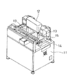
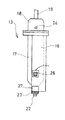
図3は従来の接着剤塗布装置の斜視図であり、図4は接着塗布装置の接着剤貯蔵タンクである塗布ヘッドの側面図、図5はその断面図である。
【0003】
図3に示すように、接着剤塗布装置の基台11の後方には、X方向に移動自在のXテーブル12が配置されており、このXテーブル12には塗布ヘッド13が装着されている。また、基台11の中央には、Y方向に移動自在のYテーブル14が配置され、このYテーブル14には、基板15を取り付けるようになっている。
【0004】
図4、図5において、塗布ヘッド13は、基板15上などに接着剤を一定量ずつ吐出し塗布するものであり、主として、タンクホルダ16と、このタンクホルダ16の中に装着される半透明で樹脂製のタンク17と、キャップ18とから構成されている。キャップ18は、Xテーブル12に内蔵された駆動装置(図示せず)によって上下動および回転するシャフト19に上部側で固定されているとともに、下部側には複数本のボルト20によってタンクホルダ16が固定されている。タンクホルダ16は、前面を取り除くことによって開口部を有しており、この開口部に、タンク17が着脱自在に装着される。タンク17の下端には漏斗状の吐出口21が形成されており、この吐出口21には、ノズル22が、タンクホルダ16の下端に装着したノズルホルダ23から下方に突出して取り付けられている。
【0005】
また、キャップ18には、圧縮空気がタンク17内へ送りこまれるように吸気口24が設けられおり、タンクホルダ16の下端近くには、接着剤25の残留量を検出するセンサ26が埋設されている。
【0006】
タンクホルダ16とノズルホルダ23の間にはヒータ27が取りつけられており、このヒータ27でノズルホルダ23が温められる。そして、ノズルホルダ23の温度を測定し、これを一定に保つためのサーミスタ28がタンクホルダ16の下端に取り付けられている。
【0007】
タンク17内には、このタンク17に接着剤25が満たされると、その上から金属製のリング29aが嵌合された樹脂製のフロート29bが入れられる。このフロート29bが、接着剤25を均一に押し出すとともに、タンクホルダ16に埋設したセンサ26によって接着剤25の残量が僅かになったことを検知する。また、タンク17の上端面とキャップ18の間、タンク17の吐出口21の外周面とノズルホルダ23の間には、タンク17内の気密を保つために、それぞれパッキン30およびパッキン31が装着されている。
【0008】
以下、上記構成において作用を説明する。
まず、タンク17を取り外し、接着剤25を入れ、その後、タンクホルダ16に取り付ける。次に、ヒータ27に電流を流し、サーミスタ28で温度を測定して所要の温度に上昇させ、この温度を一定に保持する。そして、Yテーブル14の上に基板15を取り付けて接着剤塗布装置を稼働させる。吸気口21から所定の時間圧縮空気が供給されると、この圧縮空気がフロート29bを下方に押し下げ、ノズル22から一定量の接着剤25が吐き出される。同時にシャフト19が下降し、基板15に接着剤25が塗布される。
【0009】
タンク17内の残量が減り、タンクホルダ16のセンサ26の位置までフロート29bが下がってくると、タンク17を交換する警報ランプ(図示せず)が点灯する。このようにして、接着剤25を基板15に塗布するようになっている。
【0010】
なお、接着剤塗布装置における信頼性は、接着剤25の塗布量が変化することによって大きく左右される。すなわち、接着剤25の塗布量が少ないと確実に接着できず、多すぎると電子部品の装着時に移動したり、接着剤25が基板15の電極部上に流れて接合不良を生じてしまうなどの問題を生じることになる。
【0011】
そこで、従来の上記接着剤塗布装置では、この接着剤塗布装置の起動時に、テスト用の接着部である板材(図示せず)に対して、接着剤25をテスト塗布し、適正な塗布状態となるように塗布ヘッド13に導入する高圧気体の圧力(以下、これを吐出圧力と称する)を調整したり、あるいは、基板15に対する接着剤25の本塗布工程に先立って試験的に前記板材の塗布点に対して、接着剤25をテスト塗布し、その塗布点の接着剤25の面積を演算し、接着剤25の面積が所定の許容範囲になるまで、または所定回数に達するまで塗布条件を補正してテスト塗布を繰り返し、その面積が許容範囲になるようにしていた。
【0012】
【発明が解決しようとする課題】
しかし、上記のような接着剤塗布装置では、電子部品を実装すべき基板15に対して、接着剤25を塗布している間にノズル22に、硬化した接着剤25が付着して詰まりを生じたり、周囲の温度条件が変化したりして、適正な塗布状態が得られなくなることがあり、信頼性の高い塗布ができないという問題があった。
【0013】
さらに、基板15に対する接着剤25の本塗布工程に先立って試験的に接着剤25を板材の塗布点にテスト塗布し、その塗布点の接着剤25の面積の演算を行っても、塗布点の接着剤25の高さが一定になるとは限らないため、接着剤25の面積が所定の許容範囲内であっても塗布量(塗布体積)は非常に大きなバラツキが生じて、接着剤硬化前後の基板15上に実装された電子部品の保持力に非常に大きなバラツキを与える課題があった。
【0014】
本発明は上記課題を解決するもので、信頼性の高い塗布ができる接着剤塗布装置および接着剤塗布方法を提供することを目的とする。
【0015】
【課題を解決するための手段】
上記課題を解決するために本発明の接着剤塗布装置は、基板に対する接着剤の本塗布工程に先立って試験的に接着剤をテスト用の接着部の塗布点に吐出させて、テスト塗布する接着剤塗布装置であって、前記テスト用の接着部の塗布点に吐出された接着剤の重量を測定する重量測定部と、制御部とを設け、前記制御部は、テスト塗布した際に、接着剤の重量が許容重量範囲内であり、かつ、その回の塗布重量から前回の塗布重量を差し引いた塗布重量変動量が許容重量変動範囲内に達してから本塗布工程に移行させるものである。また、本発明の他の接着剤塗布装置は、基板に対する接着剤の本塗布工程に先立って試験的に接着剤をテスト用の接着部の塗布点に吐出させて、テスト塗布する接着剤塗布装置であって、前記テスト用の接着部の塗布点に塗布された接着剤の面積を測定する認識部と、制御部とを設け、前記制御部は、テスト塗布した際に、接着剤の面積が許容面積範囲内であり、かつ、その回の塗布面積から前回の塗布面積を差し引いた塗布面積変動量が許容面積変動範囲内に達してから本塗布工程に移行させるものである。
【0016】
必要に応じて、制御部は、テスト用の接着部の塗布点の塗布回数が許容設定回数に達してから本塗布工程に移行させる。
また、1つの電子部品に対して複数の塗布点を有する場合には、制御部により、前記複数の塗布点の接着剤の重量の合計が許容範囲になると、本塗布工程に移行させる。
【0017】
さらに、テスト用の接着部の塗布点に塗布された接着剤の面積を測定する認識部を設け、制御部は、前記塗布点の接着剤の面積が許容範囲内に達してから本塗布工程に移行させるとよい。
【0018】
また、本発明の接着剤塗布方法は、基板に対する接着剤の本塗布工程に先立って試験的に接着剤をテスト用の接着部の塗布点に吐出させて、テスト塗布する接着剤塗布方法であって、前記テスト用の接着部の塗布点に吐出された接着剤の重量を測定し、前記塗布点の接着剤の重量が許容範囲内であり、かつ、その回の塗布重量から前回の塗布重量を差し引いた塗布重量変動量が許容重量変動範囲内に達すると本塗布工程に移行させる。また、本発明の他の接着剤塗布方法は、基板に対する接着剤の本塗布工程に先立って試験的に接着剤をテスト用の接着部の塗布点に吐出させて、テスト塗布する接着剤塗布方法であって、前記テスト用の接着部の塗布点に塗布された接着剤の面積を測定し、前記塗布点の接着剤の面積が許容範囲内であり、かつ、その回の塗布面積から前回の塗布面積を差し引いた塗布面積変動量が許容面積変動範囲内に達すると本塗布工程に移行させる。
【0019】
必要に応じて、テスト用の接着部の塗布点の塗布回数が許容設定回数に達してから本塗布工程に移行させる。
また、1つの電子部品に対して複数の塗布点を有する場合に、前記複数の塗布点の接着剤の重量の合計が許容範囲内になると、本塗布工程に移行させる。
【0020】
さらに、テスト用の接着部の塗布点に塗布された接着剤の面積を測定し、前記塗布点の接着剤の面積が許容範囲内に達すると本塗布工程に移行させる。
上記構成および方法により、接着剤の塗布量にバラツキがなくなり、信頼性の高い塗布ができる。
【0021】
【発明の実施の形態】
以下、本発明の実施の形態を図面により説明する。
図1に示すように、接着剤塗布装置の基台(図示せず)には、X方向に移動自在のXテーブル1が配置されており、このXテーブル1には、接着剤を吐出させて、塗布する塗布ヘッド2を装着している。基台の中央には、Y方向に移動自在のYテーブル3が配置されており、このYテーブル3上には、基板4が取り付けられるようになっている。また、Xテーブル1には、カメラとレンズよりから構成されて接着剤の塗布面積を測定する認識部5が設けられている。また、Yテーブル3上には、テスト用の接着部である板材7が取り付けられる捨て打ちステーション6が設けられ、この捨て打ちステーション6の板材7に、テスト用に吐出された接着剤の重量が図示しない重量測定部により測定されるようになっている。これらのXテーブル1、塗布ヘッド2、Yテーブル3、認識部5は、図示しない制御部によって制御される。
【0022】
この制御部の制御動作を図2のフローチャートを参照して説明する。
図2に示すように、まず、ステップ1で塗布回数Nが1回目であることが認識され、ステップ2で1回目の捨て打ちがなされた後、ステップ3で接着剤が塗布された板材7の塗布点の塗布面積S1が測定され、ステップ4で塗布重量W1が測定される。その後、ステップ5で、この接着剤塗布装置において使用者が任意に設定するテスト塗布の設定回数n(nは自然数、例えば9回)より塗布回数Nが大きいか否かの判断がされ、塗布回数Nが設定回数nより大きくない場合、すなわち塗布回数Nが設定回数n以下である場合にはステップ6に進んで塗布回数が1回増やされ、ステップ2に戻る。
【0023】
一方、塗布回数Nが設定回数nより大きいと判断されると、ステップ7に進んで今回測定された塗布面積SNから前回測定された塗布面積SN−1が差し引かれて塗布面積SNの変動である変動面積Sが演算される。ステップ8で、変動面積Sが、予め設定された設定面積S1よりも小さいか否かが判断される。変動面積Sが設定面積S1より小さい場合は、塗布面積SNが安定したと判断してステップ9に進む。一方、変動面積Sが設定面積S1より小さくない場合、すなわち設定面積S1以上である場合は、塗布面積SNが安定していないと判断してステップ6を介してステップ2に戻り、再度捨て打ち動作が行われる。
【0024】
次に、ステップ9で、今回測定された塗布面積SNが、この接着剤塗布装置において予め設定された最大許容面積S2より小さいかか否かが判断される。塗布面積SNが最大許容面積S2より小さい場合には、塗布面積SNが塗布条件に適していると判断されてステップ10に進む。一方、塗布面積SNが最大許容面積S2より小さくない場合、すなわち最大許容面積S2以上である場合には塗布面積SNが大き過ぎると判断されて、ステップ6を介して、ステップ2に戻り再度捨て打ち動作が行われる。
【0025】
ステップ10で、今回測定された接着剤の塗布重量WNから前回測定された接着剤の塗布重量WN-1が差し引かれて塗布重量WNの変動である変動重量Wが演算される。ステップ11で、変動重量Wが設定重量W1よりも小さい場合は、塗布重量WNが安定したと判断して、ステップ12に進む。一方、ステップ11で、変動重量Wを予め設定された設定重量W1と比較し、変動重量Wが設定重量W1よりも小さくない場合、すなわち設定重量W1以上である場合には、塗布重量WNが安定していないと判断してステップ6を介してステップ2に戻り、再度捨て打ち動作が行われる。
【0026】
ステップ12で、今回測定された塗布重量WNが、この接着剤塗布装置において予め設定された最大許容重量W2より小さいか否かが判断される。塗布重量WNが最大許容重量W2より小さい場合には、塗布重量WNが塗布条件に適していると判断されて、ステップ13で本塗布がスタートされる。一方、塗布重量WNが最大許容重量W2より小さくない場合、すなわち最大許容重量W2以上である場合には、塗布重量WNが大き過ぎると判断されて、ステップ6を介してステップ2に戻り、再度捨て打ち動作が行われる。
【0027】
このように、塗布面積SNだけでなく、塗布重量WNが許容範囲内に達した後に、本塗布工程に移行されるため、本塗布工程においても基板4に最適な塗布面積SNおよび塗布重量WNで接着剤を塗布することができ、すなわち、塗布体積や塗布高さも適切なものとなる。また、板材の塗布点の塗布回数が許容設定回数に達してから本塗布工程に移行させることにより、一層安定した状態で接着剤を基板に対して塗布することができる。
【0028】
なお、上記制御部は、1つの電子部品に対して複数の塗布点を有する場合に、制御部は、前記複数の塗布点の接着剤の重量の合計が許容範囲になると、本塗布工程に移行させる機能も有しており、これにより、各電子部品についても基板に適した塗布量の接着剤を塗布することができる。
【0029】
【発明の効果】
以上のように本発明によれば、接着部の塗布点に吐出された接着剤の重量を測定し、前記塗布点の重量が許容範囲内に達すると本塗布工程に移行させることにより、本塗布工程に移行する前に、予め最適な塗布重量および塗布量(塗布体積)を安定して吐出できる状態とできるため、基板に電子部品を装着するのに適した塗布重量、すなわち塗布体積の接着剤を塗布することができる。
【0030】
また、接着剤の塗布点の塗布回数が許容設定回数に達してから本塗布工程に移行させることにより、初期の不安定な状態で本塗布工程に移行することが防止できるため、基板に、一層安定した状態で接着剤を塗布することができる。
【0031】
さらに、1つの電子部品に対して複数の塗布点を有する場合に、塗布点の接着剤の重量の合計が許容範囲内に達すると、本塗布工程に移行させることにより、各電子部品についても基板に適した塗布量の接着剤を塗布することができる。
【0032】
また、接着剤の塗布重量により本塗布工程への移行を判断することに加えて、接着部の塗布点に塗布された接着剤の面積を測定し、前記塗布点の接着剤の面積が許容範囲内に達すると本塗布工程に移行させることにより、塗布点に塗布された接着剤の面積が安定するとともに高さも一定となるため、最適な接着強度が常に得られるようになる。
【0033】
このことにより、接着剤の塗布量が少ないために起こる基板に対する電子部品の不確実な装着、また、多すぎることにより起こる電子部品の装着時の移動や接着剤が基板の電極上に流れて発生する接合不良などの問題を解消することができる。
【図面の簡単な説明】
【図1】本発明の実施の形態にかかる接着剤塗布装置の斜視図である。
【図2】同実施の形態にかかる接着剤塗布装置の制御動作を示すフローチャートである。
【図3】接着剤塗布装置の斜視図である。
【図4】接着剤塗布装置の塗布ヘッドの側面図である。
【図5】接着剤塗布装置の塗布ヘッドの断面図である。
【符号の説明】
1 Xテーブル
2 塗布ヘッド
3 Yテーブル
4 基板
5 認識部
6 捨て打ちステーション
7 板材[0001]
BACKGROUND OF THE INVENTION
The present invention relates to an adhesive application device and an adhesive application method for applying an adhesive for temporarily fixing a mounted electronic component to a plate material.
[0002]
[Prior art]
An example of a conventional adhesive application device will be described with reference to FIGS.
FIG. 3 is a perspective view of a conventional adhesive application device, FIG. 4 is a side view of an application head which is an adhesive storage tank of the adhesive application device, and FIG. 5 is a sectional view thereof.
[0003]
As shown in FIG. 3, an X table 12 movable in the X direction is disposed behind the
[0004]
4 and 5, the
[0005]
The
[0006]
A
[0007]
When the
[0008]
Hereinafter, the operation of the above configuration will be described.
First, the
[0009]
When the remaining amount in the
[0010]
Note that the reliability of the adhesive applicator greatly depends on changes in the amount of
[0011]
Therefore, in the above-described conventional adhesive application device, when the adhesive application device is activated, the
[0012]
[Problems to be solved by the invention]
However, in the adhesive application apparatus as described above, the cured adhesive 25 adheres to the
[0013]
Further, prior to the actual application process of the
[0014]
The present invention solves the above-described problems, and an object thereof is to provide an adhesive application device and an adhesive application method capable of applying with high reliability.
[0015]
[Means for Solving the Problems]
In order to solve the above-mentioned problems, the adhesive application device of the present invention is an adhesive that performs test application by discharging an adhesive to the application point of a test adhesive portion prior to the main application process of the adhesive to the substrate. a agent applying device, a weight measuring unit for measuring the weight of the adhesive discharged to the application point of the bonding portion for the test, provided a control section, wherein, when tested coated, The adhesive weight is within the allowable weight range, and after the coating weight fluctuation amount obtained by subtracting the previous coating weight from the coating weight at that time reaches the allowable weight fluctuation range, the process proceeds to the coating process. . In addition, another adhesive application device of the present invention is an adhesive application device that performs test application by discharging an adhesive to the application point of a test adhesive portion prior to the main application step of the adhesive to the substrate. A recognition unit for measuring the area of the adhesive applied to the application point of the test adhesive unit, and a control unit, and the control unit has an adhesive area when the test application is performed. It is within the allowable area range, and after the application area fluctuation amount obtained by subtracting the previous application area from the application area at that time reaches the allowable area fluctuation range, the present application process is started.
[0016]
If necessary, the control unit shifts to the main application step after the application number of the application point of the test adhesive portion reaches the allowable set number.
When a plurality of application points are provided for one electronic component, the control unit shifts to the main application step when the total weight of the adhesives at the plurality of application points falls within an allowable range.
[0017]
Furthermore, a recognition unit for measuring the area of the adhesive applied to the application point of the test adhesive part is provided, and the control unit performs the main application process after the area of the adhesive at the application point reaches an allowable range. It is good to migrate.
[0018]
Further, the adhesive coating method of the present invention is an adhesive coating method in which a test is performed by discharging an adhesive to the application point of a test adhesive portion prior to the main application step of the adhesive to the substrate. Then, the weight of the adhesive discharged to the application point of the test adhesive portion is measured, the weight of the adhesive at the application point is within an allowable range , and the previous application weight is determined from the application weight at that time. coating weight variation by subtracting the causes shifts in the allowable weight variation range when it reaches the coating process. Further, another adhesive application method of the present invention is an adhesive application method in which a test application is performed by discharging an adhesive to the application point of the test adhesive portion prior to the main application step of the adhesive to the substrate. The area of the adhesive applied to the application point of the test adhesive portion is measured, the area of the adhesive at the application point is within an allowable range, and the previous application area is determined from the previous application area. When the application area fluctuation amount after subtracting the application area reaches within the allowable area fluctuation range, the present application process is started.
[0019]
If necessary, the application process is shifted to the application process after the application number of the application point of the test adhesive portion reaches the allowable set number.
Further, when a plurality of application points are provided for one electronic component, when the total weight of the adhesives at the plurality of application points is within an allowable range, the process proceeds to the application process.
[0020]
Further, the area of the adhesive applied to the application point of the test adhesive portion is measured, and when the area of the adhesive at the application point reaches an allowable range, the process proceeds to the main application step.
With the above configuration and method, there is no variation in the amount of adhesive applied, and highly reliable application can be achieved.
[0021]
DETAILED DESCRIPTION OF THE INVENTION
Hereinafter, embodiments of the present invention will be described with reference to the drawings.
As shown in FIG. 1, an X table 1 that is movable in the X direction is disposed on a base (not shown) of the adhesive application device. Adhesive is discharged onto the X table 1. The application head 2 for application is mounted. A Y table 3 movable in the Y direction is disposed at the center of the base, and a substrate 4 is attached on the Y table 3. In addition, the X table 1 is provided with a
[0022]
The control operation of this control unit will be described with reference to the flowchart of FIG.
As shown in FIG. 2, first, it is recognized that the number of times of application N is the first time in
[0023]
On the other hand, when it is determined that the application number N is larger than the set number n, the process proceeds to step 7 where the previously measured application area S N-1 is subtracted from the application area S N measured this time, to obtain the application area S N. A fluctuation area S which is a fluctuation is calculated. In step 8, it is determined whether or not the variable area S is smaller than a preset set area S1. If the variation area S is smaller than the set area S1, it is determined that the application area SN is stable, and the process proceeds to step 9. On the other hand, when the fluctuation area S is not smaller than the set area S1, that is, when it is equal to or larger than the set area S1, it is determined that the application area S N is not stable, and the process returns to step 2 via
[0024]
Next, in step 9, it is determined whether or not the currently measured application area SN is smaller than the maximum allowable area S2 set in advance in the adhesive application device. If the application area SN is smaller than the maximum allowable area S2, it is determined that the application area SN is suitable for the application conditions, and the process proceeds to step 10. On the other hand, when the application area S N is not smaller than the maximum allowable area S2, that is, when the application area S N is equal to or larger than the maximum allowable area S2, it is determined that the application area S N is excessively large. Discarding action is performed.
[0025]
In step 10, the adhesive weight WN-1 measured last time is subtracted from the adhesive weight WN measured this time to calculate a fluctuation weight W that is a fluctuation of the coating weight WN. If the variable weight W is smaller than the set weight W1 in
[0026]
In
[0027]
Thus, since not only the application area S N but also the application weight W N reaches the allowable range, the process proceeds to the main application process. Therefore, the optimum application area S N and application to the substrate 4 also in the main application process. The adhesive can be applied with the weight W N , that is, the application volume and the application height are also appropriate. In addition, the adhesive can be applied to the substrate in a more stable state by shifting to the main application step after the application number of the application points of the plate material reaches the allowable set number.
[0028]
When the control unit has a plurality of application points for one electronic component, the control unit proceeds to the application process when the total weight of the adhesives at the plurality of application points falls within an allowable range. Therefore, it is possible to apply a suitable amount of adhesive to the substrate for each electronic component.
[0029]
【The invention's effect】
As described above, according to the present invention, the weight of the adhesive discharged to the application point of the adhesive portion is measured. Since the optimum application weight and application amount (application volume) can be stably discharged in advance before proceeding to the process, an application weight suitable for mounting electronic components on the substrate, that is, an adhesive with an application volume Can be applied.
[0030]
In addition, by shifting to the main application process after the number of times of application of the adhesive application point reaches the allowable set number, it is possible to prevent the main application process from shifting to the initial unstable state. The adhesive can be applied in a stable state.
[0031]
Furthermore, when there are a plurality of application points for one electronic component, if the total weight of the adhesives at the application point reaches within an allowable range, a transition is made to this application step, so that each electronic component is also a substrate. A suitable amount of adhesive can be applied.
[0032]
In addition to determining the transition to the main application process based on the application weight of the adhesive, the area of the adhesive applied to the application point of the adhesive portion is measured, and the area of the adhesive at the application point is within an allowable range. When reaching the inside, by shifting to the present application step, the area of the adhesive applied to the application point is stabilized and the height becomes constant, so that the optimum adhesive strength can always be obtained.
[0033]
This causes uncertain mounting of electronic components to the board due to the small amount of adhesive applied, and movement and adhesive flow on the electrodes of the board due to excessive mounting of electronic components. Problems such as poor bonding can be solved.
[Brief description of the drawings]
FIG. 1 is a perspective view of an adhesive application device according to an embodiment of the present invention.
FIG. 2 is a flowchart showing a control operation of the adhesive application device according to the embodiment;
FIG. 3 is a perspective view of an adhesive application device.
FIG. 4 is a side view of a coating head of the adhesive coating device.
FIG. 5 is a cross-sectional view of a coating head of the adhesive coating device.
[Explanation of symbols]
1 X table 2 Coating head 3 Y table 4
Claims (10)
前記テスト用の接着部の塗布点に吐出された接着剤の重量を測定する重量測定部と、
制御部とを設け、
前記制御部は、テスト塗布した際に、接着剤の重量が許容重量範囲内であり、かつ、その回の塗布重量から前回の塗布重量を差し引いた塗布重量変動量が許容重量変動範囲内に達してから本塗布工程に移行させる接着剤塗布装置。Prior to the main application process of the adhesive to the substrate, an adhesive application apparatus for test application by discharging the adhesive to the application point of the test adhesive part on a test basis,
A weight measuring unit that measures the weight of the adhesive discharged to the application point of the test adhesive unit ;
And a control section is provided,
When the test application is performed, the weight of the adhesive is within the allowable weight range, and the application weight fluctuation amount obtained by subtracting the previous application weight from the application weight at that time reaches the allowable weight fluctuation range. Adhesive applicator that shifts to this application process .
前記テスト用の接着部の塗布点に塗布された接着剤の面積を測定する認識部と、A recognition unit for measuring the area of the adhesive applied to the application point of the test adhesive unit;
制御部とを設け、A control unit,
前記制御部は、テスト塗布した際に、接着剤の面積が許容面積範囲内であり、かつ、その回の塗布面積から前回の塗布面積を差し引いた塗布面積変動量が許容面積変動範囲内に達してから本塗布工程に移行させる接着剤塗布装置。When the test application is performed, the area of the adhesive is within the allowable area range, and the application area fluctuation amount obtained by subtracting the previous application area from the application area at that time reaches the allowable area fluctuation range. Adhesive applicator that shifts to the main application process.
1つの電子部品に対して複数の塗布点を有する場合に、制御部は、前記複数の塗布点の接着剤の重量の合計が許容範囲内に達すると本塗布工程に移行させる請求項1〜3の何れか1項に記載の接着剤塗布装置。 A weight measuring unit is provided to measure the weight of the adhesive discharged to the application point of the test adhesive part,
When a plurality of application points for one electronic component, the control unit, according to claim 1 to 3 the total weight of the adhesive of the plurality of coating point shifts to the present application step is reached within the tolerance The adhesive agent coating apparatus according to any one of the above.
前記テスト用の接着部の塗布点に吐出された接着剤の重量を測定し、
前記塗布点の接着剤の重量が許容範囲内であり、かつ、その回の塗布重量から前回の塗布重量を差し引いた塗布重量変動量が許容重量変動範囲内に達すると本塗布工程に移行させる接着剤塗布方法。Prior to the main application step of the adhesive to the substrate, the adhesive is applied to the test point by ejecting the adhesive to the application point of the test adhesive part for testing.
Measure the weight of the adhesive discharged to the application point of the test adhesive part,
Bonding the weight of the adhesive application point is within the allowable range, and to shift when it reaches the coating step in the coating weight variation obtained by subtracting the previous coating weight from the coating weight of the times within the allowable weight range of variation Agent coating method.
前記テスト用の接着部の塗布点に塗布された接着剤の面積を測定し、Measure the area of the adhesive applied to the application point of the test adhesive part,
前記塗布点の接着剤の面積が許容範囲内であり、かつ、その回の塗布面積から前回の塗布面積を差し引いた塗布面積変動量が許容面積変動範囲内に達すると本塗布工程に移行させる接着剤塗布方法。Adhesion that shifts to the present application step when the area of the adhesive at the application point is within an allowable range, and the amount of change in the application area obtained by subtracting the previous application area from the application area at the time reaches the allowable area change range. Agent coating method.
Priority Applications (1)
| Application Number | Priority Date | Filing Date | Title |
|---|---|---|---|
| JP31866995A JP3625552B2 (en) | 1995-12-07 | 1995-12-07 | Adhesive application apparatus and adhesive application method |
Applications Claiming Priority (1)
| Application Number | Priority Date | Filing Date | Title |
|---|---|---|---|
| JP31866995A JP3625552B2 (en) | 1995-12-07 | 1995-12-07 | Adhesive application apparatus and adhesive application method |
Publications (2)
| Publication Number | Publication Date |
|---|---|
| JPH09155267A JPH09155267A (en) | 1997-06-17 |
| JP3625552B2 true JP3625552B2 (en) | 2005-03-02 |
Family
ID=18101716
Family Applications (1)
| Application Number | Title | Priority Date | Filing Date |
|---|---|---|---|
| JP31866995A Expired - Fee Related JP3625552B2 (en) | 1995-12-07 | 1995-12-07 | Adhesive application apparatus and adhesive application method |
Country Status (1)
| Country | Link |
|---|---|
| JP (1) | JP3625552B2 (en) |
Cited By (1)
| Publication number | Priority date | Publication date | Assignee | Title |
|---|---|---|---|---|
| US8821959B2 (en) | 2008-02-18 | 2014-09-02 | Musashi Engineering, Inc. | Method for applying liquid material, device therefor, and program therefor |
Families Citing this family (3)
| Publication number | Priority date | Publication date | Assignee | Title |
|---|---|---|---|---|
| JP4722256B2 (en) * | 2000-06-16 | 2011-07-13 | パナソニック株式会社 | Adhesive application method and adhesive application device |
| JP5406770B2 (en) * | 2010-03-26 | 2014-02-05 | パナソニック株式会社 | Method and system for determining the amount of active species released from the emitter to the measurement space with respect to the measurement target |
| KR101393678B1 (en) * | 2013-01-16 | 2014-05-13 | 비케이전자 주식회사 | Surface mounted apparatus |
-
1995
- 1995-12-07 JP JP31866995A patent/JP3625552B2/en not_active Expired - Fee Related
Cited By (2)
| Publication number | Priority date | Publication date | Assignee | Title |
|---|---|---|---|---|
| US8821959B2 (en) | 2008-02-18 | 2014-09-02 | Musashi Engineering, Inc. | Method for applying liquid material, device therefor, and program therefor |
| TWI471177B (en) * | 2008-02-18 | 2015-02-01 | 武藏工業股份有限公司 | A method of coating a liquid material, a device thereof, and a memory medium having a memory |
Also Published As
| Publication number | Publication date |
|---|---|
| JPH09155267A (en) | 1997-06-17 |
Similar Documents
| Publication | Publication Date | Title |
|---|---|---|
| US6213356B1 (en) | Bump forming apparatus and bump forming method | |
| EP2040054B1 (en) | Method and apparatus for leak testing closed containers | |
| US8365952B2 (en) | Compensating pressure controller for fluid dispenser and method | |
| JP3625552B2 (en) | Adhesive application apparatus and adhesive application method | |
| CN101005904A (en) | Device for discharging fixed quantity of liquid | |
| WO1993018409A1 (en) | Dispensing device | |
| US20070090126A1 (en) | Liquid material discharge apparatus and liquid material discharge method | |
| CN107537705B (en) | Flux coating method and flux coating device | |
| US5878957A (en) | Method and system for precise discharge determination | |
| KR0138992B1 (en) | Device for rapid applying of pastes and adhesives at discrete points, especially for surface mounting of components at circuit cards | |
| JPH01307470A (en) | Coating applicator for viscous fluid | |
| JPH0282685A (en) | Application apparatus | |
| KR20000011150A (en) | Filling apparatus | |
| JPH0845816A (en) | Liquid supply device | |
| JP2012139627A (en) | Liquid supply device and liquid supply method | |
| JP4197107B2 (en) | Coating equipment | |
| JP4337349B2 (en) | Molten metal supply method and molten metal supply device | |
| JPS6372372A (en) | Viscous material emitting apparatus | |
| JPH05161864A (en) | Paste applicator | |
| JP3605468B2 (en) | Liquid material discharge device | |
| JP2009078201A (en) | Viscous fluid application device | |
| JPH04244257A (en) | Liquid applying apparatus | |
| JP3216288B2 (en) | Liquid coating device | |
| JP2000226098A (en) | Filling control method for low-viscosity liquid and device therefor | |
| JP3472416B2 (en) | Reservoir container for dispensed liquid |
Legal Events
| Date | Code | Title | Description |
|---|---|---|---|
| A131 | Notification of reasons for refusal |
Free format text: JAPANESE INTERMEDIATE CODE: A131 Effective date: 20040203 |
|
| A521 | Request for written amendment filed |
Free format text: JAPANESE INTERMEDIATE CODE: A523 Effective date: 20040405 |
|
| TRDD | Decision of grant or rejection written | ||
| A01 | Written decision to grant a patent or to grant a registration (utility model) |
Free format text: JAPANESE INTERMEDIATE CODE: A01 Effective date: 20041102 |
|
| A61 | First payment of annual fees (during grant procedure) |
Free format text: JAPANESE INTERMEDIATE CODE: A61 Effective date: 20041130 |
|
| FPAY | Renewal fee payment (event date is renewal date of database) |
Free format text: PAYMENT UNTIL: 20071210 Year of fee payment: 3 |
|
| FPAY | Renewal fee payment (event date is renewal date of database) |
Free format text: PAYMENT UNTIL: 20081210 Year of fee payment: 4 |
|
| FPAY | Renewal fee payment (event date is renewal date of database) |
Free format text: PAYMENT UNTIL: 20091210 Year of fee payment: 5 |
|
| FPAY | Renewal fee payment (event date is renewal date of database) |
Free format text: PAYMENT UNTIL: 20091210 Year of fee payment: 5 |
|
| FPAY | Renewal fee payment (event date is renewal date of database) |
Free format text: PAYMENT UNTIL: 20101210 Year of fee payment: 6 |
|
| FPAY | Renewal fee payment (event date is renewal date of database) |
Free format text: PAYMENT UNTIL: 20101210 Year of fee payment: 6 |
|
| FPAY | Renewal fee payment (event date is renewal date of database) |
Free format text: PAYMENT UNTIL: 20111210 Year of fee payment: 7 |
|
| FPAY | Renewal fee payment (event date is renewal date of database) |
Free format text: PAYMENT UNTIL: 20111210 Year of fee payment: 7 |
|
| FPAY | Renewal fee payment (event date is renewal date of database) |
Free format text: PAYMENT UNTIL: 20121210 Year of fee payment: 8 |
|
| FPAY | Renewal fee payment (event date is renewal date of database) |
Free format text: PAYMENT UNTIL: 20121210 Year of fee payment: 8 |
|
| FPAY | Renewal fee payment (event date is renewal date of database) |
Free format text: PAYMENT UNTIL: 20131210 Year of fee payment: 9 |
|
| LAPS | Cancellation because of no payment of annual fees |