JP3625527B2 - Easy chair - Google Patents
Easy chair Download PDFInfo
- Publication number
- JP3625527B2 JP3625527B2 JP15636195A JP15636195A JP3625527B2 JP 3625527 B2 JP3625527 B2 JP 3625527B2 JP 15636195 A JP15636195 A JP 15636195A JP 15636195 A JP15636195 A JP 15636195A JP 3625527 B2 JP3625527 B2 JP 3625527B2
- Authority
- JP
- Japan
- Prior art keywords
- leg unit
- armrest
- frame
- footrest
- side member
- Prior art date
- Legal status (The legal status is an assumption and is not a legal conclusion. Google has not performed a legal analysis and makes no representation as to the accuracy of the status listed.)
- Expired - Fee Related
Links
Images


Classifications
-
- A—HUMAN NECESSITIES
- A47—FURNITURE; DOMESTIC ARTICLES OR APPLIANCES; COFFEE MILLS; SPICE MILLS; SUCTION CLEANERS IN GENERAL
- A47C—CHAIRS; SOFAS; BEDS
- A47C4/00—Foldable, collapsible or dismountable chairs
- A47C4/04—Folding chairs with inflexible seats
- A47C4/18—Folding chairs with inflexible seats having a frame made of metal
- A47C4/20—Folding chairs with inflexible seats having a frame made of metal with legs pivotably connected to seat or underframe
- A47C4/24—Folding chairs with inflexible seats having a frame made of metal with legs pivotably connected to seat or underframe with cross legs
- A47C4/26—Folding chairs with inflexible seats having a frame made of metal with legs pivotably connected to seat or underframe with cross legs of adjustable type
-
- A—HUMAN NECESSITIES
- A47—FURNITURE; DOMESTIC ARTICLES OR APPLIANCES; COFFEE MILLS; SPICE MILLS; SUCTION CLEANERS IN GENERAL
- A47C—CHAIRS; SOFAS; BEDS
- A47C1/00—Chairs adapted for special purposes
- A47C1/02—Reclining or easy chairs
- A47C1/031—Reclining or easy chairs having coupled concurrently adjustable supporting parts
- A47C1/034—Reclining or easy chairs having coupled concurrently adjustable supporting parts the parts including a leg-rest or foot-rest
- A47C1/035—Reclining or easy chairs having coupled concurrently adjustable supporting parts the parts including a leg-rest or foot-rest in combination with movably coupled seat and back-rest, i.e. the seat and back-rest being movably coupled in such a way that the extension mechanism of the foot-rest is actuated at least by the relative movements of seat and backrest
Landscapes
- Health & Medical Sciences (AREA)
- Dentistry (AREA)
- General Health & Medical Sciences (AREA)
- Chairs For Special Purposes, Such As Reclining Chairs (AREA)
- Chair Legs, Seat Parts, And Backrests (AREA)
- Seats For Vehicles (AREA)
Description
【0001】
【産業上の利用分野】
本発明は、安楽椅子に係わり、さらに詳細には、背部と足置きとを備えるとともに運搬および整理を容易とするために押し広げによる組み立てと平たくなるまでの折り畳みが可能なタイプの安楽椅子に関するものである。
【0002】
【従来の技術】
このタイプの椅子は、広く屋外で(庭やキャンピング等において)利用され、あるいは、臨時の椅子として使用されている。それについては詳細に述べる必要はないであろう。
【0003】
通常これらの椅子は、1枚の布が張り渡される3つの部材、特に背部・シート・足置きに対して協同的に設けられる基部から構成される。接続機構により、背部を押し広げて傾斜状態にすると、同様に足置きも押し広げて傾斜状態とし、結果的に寝そべる状態にまで椅子が組み立てられたときには、足を休めて大きな快適感を得ることができる。(例えば、US−A−2,195,091を参照。)
【0004】
【発明が解決しようとする課題】
しかしながら、上記のタイプの椅子においては、肘掛けは、基部に剛直に固定されており、背部と足置きとの間の動きの伝達は、時には肘置きとしても知られている肘掛けの下に位置するスライド式の管を介してなされる。結果として、肘掛けは、シートの傾斜動作にかかわらず据え付け式であり、使用者の腕はこの傾斜動作に追従しない。この欠点は、快適さを増加させるものでは一切なく、加えて、機械的な接続部分は、通常かさ高いものであるので、平たくなるまで折り畳む作業および再度押し広げて組み立てる作業は、困難なものであり、特に子供にとっては困難である。それは、多数の巧妙な取り扱いを必要とするからである。接続部分の近傍においては、危険をもたらす可能性があり、つまり指を挟んでしまうおそれがある。
【0005】
本出願人が広く採用する1つの例では、基部の上端は、肘掛けの下に位置するスライド式の管に固定され、肘掛けの位置は、調整用ねじにより調整される。しかしながら、このタイプは、操作しにくい位置にロック用部材があるとともに、その位置は、使用者がシートを傾けるごとに変化するいう欠点を有している。さらに、ロック用部材を駆動することおよび椅子を押し広げて組み立てることは、1回のみの動作でなし得るものではない。
【0006】
本発明は、上記欠点を緩和するものであり、その目的とするところは、押し広げによる組み立ておよび平坦までの折り畳みが子供にとってさえも容易であり、指を挟む心配がなく、かつ、位置決めのためのロックが容易であって、確実に快適感が得られる折り畳み式の安楽椅子を提供することにある。
【0007】
【課題を解決するための手段】
概して、本発明は安楽椅子に関するものであり、以下のタイプのものである。すなわち、背部を構成するフレームと、前記背部フレームの下端近傍に接続されシートを形成する2つの平行な側方部材と、前記背部フレームに接続されるとともに互いに平行かつ前記シートの側方部材に平行な2つの肘掛けと、U字を形成する2つの枝部分が前記側方部材に接続され足置きを構成するU字形フレームと、弾性手段により前記フレームおよび前記側方部材に留められてこれらの部材間に張り渡される1枚の布と、それぞれが前記側方部材に接続された2本の平行な脚により構成される脚ユニットである前脚ユニットおよび後脚ユニットの2つの脚ユニットにより構成される基部と、前記前脚ユニットおよび前記後脚ユニットを共に結合する股状継手とを具備してなり、
前記各肘掛けは、前記側方部材に平行なスライド式ロッドを有し、前記各前脚ユニットの端部は、前記スライド式ロッドに沿ってスライド可能とされた股状継手と椅子の位置をロックする手段とを有し、前記脚ユニットの脚どうしは、連結棒により共に接続され、この連結棒は、前記前脚ユニットと股状継手とに接続され、この股状継手は、前記側方部材の後部に固定されるとともに各後脚ユニットをスライド可能とし、前記足置きのフレームの前記枝部分の上端は、前記肘掛けの端部に接続されていることを特徴としている。
【0008】
言い換えれば、背部と足置きとの間の動きの伝達は、背部・足置き・シートの側方部材・肘掛けのスライド式ロッドで形成される四辺形の形を変形させることによりなされる。この動きの間において、基部全体、特にスライド式の股状継手および側方部材の後方に位置する股状継手の位置が不変であるので、肘掛けが背部につれて動き、それによって従来技術とは対照的に、肘掛けが傾斜動作に追従することとなる。
【0009】
それゆえ、これらの特性の組み合わせは、新規かつ追い求められていたものであり、特に、背部および足置きの傾斜動作と連動する肘掛けを使用することで、快適さが高められている。
【0010】
美的であって快適さをさらに高めた実施例においては、背部を構成するフレームは、閉じておりかつ人間工学的な曲線である。
【0011】
さらに、実際には、側方部材およびフレームは、管状の金属部材により形成されている。脚ユニットは、上方を向くU字形とされU字形の枝部分どうしを結合する結合部分である基底部分にはシュー(shoes) が取り付けられている。言い換えれば、U字形の枝部分に位置する椅子の2つの前脚および2つの後脚どうしは、基底部分により結合されており、それによって安定性が高められている。特有のスライド式の股状継手は、プラスチック、特に、ポリアセタール(polyacetal)あるいはポリアミド(polyamide) により形成されている。椅子の位置をロックする部材は、偏心したタイプのカムである。
【0012】
実際的な実施例においては、足置きの枝部分は、肘掛けの端部に対してヒンジ結合されており、そのヒンジは、肘掛けのスライド式ロッドの正に端部が係合する第1のヒンジと、足置きの端部が係合する第2のヒンジとを備え、これら2つのヒンジ部は、これらを横切るピンにより接続されている。
【0013】
【実施例】
本発明を実施する方法、および、そこから派生する利点は、添付された図面により裏付けられる以下の実施例によりさらに明瞭となるであろう。
【0014】
図1は、本発明の安楽椅子を示すもので、組み立てられた状態における側面図である。
図2は、本発明の安楽椅子を示すもので、平たく折り畳まれた状態を示している。
図3は、肘掛けの部分におけるスライド式部材の詳細図である。
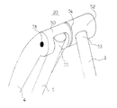
図4は、足置きと肘掛けとの間の接続を示す詳細図である。
【0015】
本発明に係る安楽椅子は、図1に組み立て状態を示すように、個別の役割をもった2つの集合体に分けることができる。すなわち、1つは、符号23で示す位置において架台状(trestle−fashion) に接続された2つの脚ユニットの組(35,36)により構成される基台であり、他の1つは、座る人を迎え入れるように構成されたものであって背部1、シート2、足置き3、2つの肘掛け4により構成される集合体である。
【0016】
前記背部1は、閉じたフレームであり、一般に矩形状であり、そして、背骨の曲がりにならうようわずかに曲げられている。
【0017】
シートの側方部材2は、それぞれが管状の金属部材によって形成され、その後部が背部1の鉛直方向の符号22で示す位置において揺動可能に取り付けられている。この場合の接続は、背部1の下端近傍において、U字形の通常の股状継手22によりなされている。この股状継手22は、U字形の基底部分が側方部材2を収容して溶接されており、かつU字形の枝部分が背部1の側部を貫通するピンを支持している。これら側方部材2は、わずかに後方側に傾斜している。
【0018】
前記2つの肘掛け4は、一端が背部1に、他端が足置き3に、それぞれ符号24および20で示す位置において接続されている。これら肘掛けは、基本的には側方部材2に平行である。各肘掛け4の下方には、スライド式ロッド5が備えられ、このスライド式ロッド5は、基部の前脚ユニット36の上端に固定された股状継手7内でスライド移動するように構成されている。
【0019】
前記足置きは、U字形であるとともに、シートの側方部材2および肘掛け4に接続されたフレームにより構成されている。肘掛け4との接続(図4参照)は、ヒンジ20によりなされ、このヒンジ20は、肘掛け4の端部と足置き3のフレームの端部とを接続するものである。足置き3と側方部材2との結合は、通常の股状継手21によりなされている。股状継手21は、肘掛け4と側方部材2とが平行を維持する高さに位置している。
【0020】
前記背部1、前記シートの側方部材2および股状継手21の下方に位置した足置き3により形成された面に1枚の布が張り渡されている。周知のように、この布は、この布に設けられた小穴と前記各部材に溶接された金属環とに交互に挿通される弾性をもった紐により前記各部材に取り付けられている。
【0021】
前記基部は、2組のU字形の脚ユニット35、36により構成されている。後脚ユニット35の2つの端部には、股状継手23が溶接により取り付けられており、この股状継手23には、前脚ユニット36の上部が接続されている。
さらに、前脚ユニット36の中央少し上方には、連結棒39(link)があり、この連結棒39は、ピン25により接続されて垂直面内で回動するように構成されている。この連結棒39の他端は、股状継手10に接続されている。
通常の方法により、脚ユニット35、36のU字形状の枝部分どうしを連結する水平連結部には、滑り止めのシュー30、31が取り付けられている。
【0022】
基部とシートとは、2点で結合されている。すなわち、1つは股状継手10であり、他の1つはスライド式の股状継手7である。股状継手10は、シートの側方部材2に取り付けられて、後脚ユニット35がこの側方部材2に関してスライドできるようになっている。スライド式の股状継手7は、基部の前脚ユニット36の上端に取り付けられ、肘掛けのロッド5が基部に対してスライドできるようになっている。
【0023】
前記肘掛け4は、図4に詳細に示すように、ヒンジ20により足置き3に接続されている。スライド式ロッド5は、肘掛け4の前方端部内に収容されている。この円柱状の端部50は、椅子の対称面に関して垂直なピン51を有し、この端部50の椅子の内方側には、足置き3の上端53を収容しかつ前記端部50と同径である他の円柱52が接続されている。これら同軸に設けられた2つの回転式円柱の回動運動は、摩擦ワッシャ54(a fliction washer) を介して行われている。ただし、このワッシャ54を設けなくとも構わない。
【0024】
椅子を傾ける際の傾斜角度は、スライド式ロッド5と股状継手7とをロックすることにより維持される。ロック機構自体は、偏心部材8によりなされる。この偏心部材8は、スライド式の股状継手7に取り付けられて、股状継手7のスライド方向に平行な軸に対して回転することができる。この偏心部材8は、スライド式ロッド5の径と同様の径の穴を有し、その穴の中心は、回転軸に対してわずかにずらされている。
【0025】
椅子の使用者を収容するための領域は、この領域を構成する部材の様々な接続関係を可能とするような四辺形、すなわち変形し得る四辺形を含んでいる。この四辺形の4隅は、
−背部1と肘掛け4との接続箇所24と、
−肘掛け4と足置き3との接続を行うヒンジ20と、
−足置き3とシートの側方部材2との接続を行う股状継手21と、
−背部1とシートの側方部材2との接続を行う股状継手22と
である。
【0026】
このように背部が後方に傾斜されたときには、接続箇所24は、股状継手22よりも後方に位置することになる。この際の動きによりスライド式ロッド5は、後方側に引かれるが、一方、側方部材2は、基部に固定されており静止状態にある。このようにして前記ヒンジ20が股状継手21に対して後方側に移動し、足置き3は、水平状態に近づく向きに回転を受けた位置に落ちつくことになる。
背部が前方側に傾斜されたとき、すなわち折り畳む際の四辺形の変形は、上記と逆になる。
【0027】
言い換えれば、椅子が前方側あるいは後方側に傾斜されたときに、基部が動くことはなく、したがってシートの側方部材2も動かない。2つの股状継手21、22は、それゆえ、定位置に位置することとなる。よって背部と足置きとは、2つの股状継手21、22を中心として回転し、肘掛けのロッド5は、前方側あるいは後方側に移動する。
【0028】
スライド動作が行われるとき、すなわち使用者が椅子の傾斜角度を変えたいときには、偏心部材8をその穴の中心がスライド式ロッドの中心と一致するように回転させる。逆に、使用者が椅子の傾斜角度をロックして選んだ位置にて固定したいときには、使用者は、偏心部材8をその穴の中心がスライド式ロッド5の中心と一致しないように回転させればよい。このとき、偏心部材8の穴の内面は、スライド式ロッド5に接触するようになり、摩擦が生じる結果として、スライドが阻止されロックされる。
【0029】
椅子を平たく折り畳みたいときには、ロッド5が股状継手7の内側を自由にスライドできる状態とされる。連結棒39は、回転ピン25により前脚ユニット36に接続されているので、基部の2つの脚ユニット35、36は、一緒に折り畳まれ、股状継手10は、後脚ユニット35の下方に向けて押下げられる。この股状継手10は、シートの側方部材2に回転可能に固定されているので、側方部材2は、股状継手10の下方への動きにつれて引っ張られる。同時に、股状継手7は、ロッド5の前方に向けて押される。一旦、この股状継手7がヒンジ20に接した後は、折り畳み動作は、股状継手22とヒンジ20とが互いに離れる向きに移動するという上述の四辺形の変形により続けられる。最後には、この四辺形は、背部1が前方側に傾き足置き3が後方側に傾き、完全につぶされる。結果は図2に示すようなものであり、椅子は完全に平たく折り畳まれている。
椅子は、上述の操作を可逆的に行うことで再度組み立てられる。
【0030】
【発明の効果】
本発明の1つの利点は、肘掛けが背部に設けられている点にある。これにより、この椅子に座る人は、シートの傾斜にかかわらず、肘掛けによる支持を利用することができる。さらに、ロック用部材8は、肘掛け4で覆われてその下方に位置しているので、接近した位置関係にあり操作することが容易である。
【0031】
上記実施例の記載から、本発明がいくつもの注目すべき利点を有していることがわかる。特に、
−1つには、椅子を容易にかつ快適なように傾斜することができることである。肘掛けは、椅子の位置にかかわらず、いつも使用者の肘の下方に位置する。さらに、椅子のある位置でのロックは、椅子の傾きにかかわらず使用者の手近に位置するたった1つの部材8を操作することにより簡単にかつ効果的な動きでもってなされる。
−もう1つには、椅子を平たく折り畳むに要求される操作および再度組み立てるに要求される操作が疑う余地がないほどに容易になされ得ることである。これは、スライドする部材の相互作用の結果として、椅子を折り畳む際にあるいは押し広げて組み立てる際にたった1つの動きが要求されるだけであることによる。
【図面の簡単な説明】
【図1】本発明の安楽椅子を示すもので、組み立てられた状態における側面図である。
【図2】本発明の安楽椅子を示すもので、平たく折り畳まれた状態を示している。
【図3】肘掛けの部分におけるスライド式部材の詳細図である。
【図4】足置きと肘掛けとの間の接続を示す詳細図である。
【符号の説明】
1 背部フレーム
2 側方部材(シートの側方部材)
3 U字形フレーム(足置き)
4 肘掛け
5 スライド式ロッド
7 股状継手
8 ロックする手段
10 股状継手
20 ヒンジ
23 股状継手
35 後脚ユニット
36 前脚ユニット
39 連結棒
50 第1のヒンジ
51 ピン
52 第2のヒンジ
53 端部
55 端部[0001]
[Industrial application fields]
The present invention relates to an easy chair, and more particularly, to an easy chair that includes a back portion and a footrest, and that can be folded and folded until flattened for easy transportation and organization. It is.
[0002]
[Prior art]
This type of chair is widely used outdoors (in the garden, camping, etc.) or as a temporary chair. There is no need to elaborate on that.
[0003]
Usually, these chairs are composed of three members on which a piece of cloth is stretched, in particular, a base portion provided cooperatively with respect to the back portion, seat, and footrest. With the connection mechanism, when the back part is pushed out and tilted, the footrest is also pushed up and tilted. As a result, when the chair is assembled to lie down, rest your legs and get a great feeling of comfort. Can do. (See, for example, US-A-2,195,091.)
[0004]
[Problems to be solved by the invention]
However, in a chair of the type described above, the armrest is rigidly fixed to the base, and the transmission of movement between the back and the footrest is located below the armrest, sometimes known as the armrest. This is done through a sliding tube. As a result, the armrest is stationary, regardless of the seat tilting motion, and the user's arm does not follow this tilting motion. This disadvantage does not increase comfort at all, and in addition, the mechanical connection is usually bulky, so it is difficult to fold until flat and to fold and assemble again. Yes, especially for children. This is because it requires a lot of clever handling. In the vicinity of the connection portion, there is a possibility of causing a danger, that is, there is a possibility that a finger is pinched.
[0005]
In one example widely adopted by the Applicant, the upper end of the base is fixed to a sliding tube located under the armrest, and the position of the armrest is adjusted by an adjusting screw. However, this type has a drawback that the locking member is located at a position where it is difficult to operate, and the position changes every time the user tilts the seat. Furthermore, driving the locking member and pushing and assembling the chair cannot be done in a single operation.
[0006]
The present invention alleviates the above-mentioned drawbacks, and the purpose of the present invention is to make it easy to fold and fold to flat even for children, without worrying about pinching fingers, and for positioning. It is an object of the present invention to provide a foldable easy chair that can be easily locked and can provide a comfortable feeling.
[0007]
[Means for Solving the Problems]
In general, the present invention relates to an easy chair and is of the following type. That is, a frame constituting the back portion, two parallel side members connected to the vicinity of the lower end of the back frame to form a seat, and connected to the back frame and parallel to each other and parallel to the side members of the seat Two armrests, a U-shaped frame in which two branch portions forming a U-shape are connected to the side member to form a footrest, and these members are fastened to the frame and the side member by elastic means. It is composed of two leg units, a front leg unit and a rear leg unit, which are leg units composed of one cloth stretched between them and two parallel legs each connected to the side member. Comprising a base and a crotch joint for joining the front leg unit and the rear leg unit together;
Each armrest has a sliding rod parallel to the side member, and the end of each front leg unit locks the position of the crotch joint and the chair that are slidable along the sliding rod. And the legs of the leg units are connected together by a connecting rod, the connecting rod being connected to the front leg unit and the crotch joint, and the crotch joint is connected to the rear part of the side member. And the rear leg unit is slidable, and the upper end of the branch portion of the footrest frame is connected to the end of the armrest.
[0008]
In other words, movement is transmitted between the back and the footrest by deforming the shape of a quadrilateral formed by the back portion, the footrest, the side member of the seat, and the sliding rod of the armrest. During this movement, the position of the entire base, in particular the slidable crotch joint and the crotch joint located behind the side members, remains unchanged, so that the armrest moves with the back, thereby contrasting with the prior art. In addition, the armrest follows the tilting motion.
[0009]
Therefore, the combination of these characteristics is new and sought after, and in particular, comfort is enhanced by using an armrest that works in conjunction with the tilting motion of the back and footrest.
[0010]
In an aesthetic and comfort-enhancing embodiment, the back frame is closed and an ergonomic curve.
[0011]
Further, in practice, the side member and the frame are formed of a tubular metal member. The leg unit is U-shaped facing upward, and a shoe is attached to a base portion that is a connecting portion that connects the U-shaped branch portions. In other words, the two front legs and the two rear legs of the chair located in the U-shaped branch part are connected to each other by the base part, thereby improving the stability. The unique slide-type crotch joint is made of plastic, in particular, polyacetal or polyamide. The member that locks the position of the chair is an eccentric type cam.
[0012]
In a practical embodiment, the footrest branch is hinged to the end of the armrest, the hinge being the first hinge that engages the end exactly of the armrest sliding rod. And a second hinge with which the end of the footrest engages, the two hinge portions being connected by a pin across them.
[0013]
【Example】
The method of practicing the present invention and the advantages derived therefrom will become more apparent from the following examples, which are supported by the accompanying drawings.
[0014]
FIG. 1 shows an easy chair of the present invention and is a side view in an assembled state.
FIG. 2 shows an easy chair of the present invention, and shows a state in which the easy chair is folded flat.
FIG. 3 is a detailed view of the sliding member in the armrest portion.
FIG. 4 is a detailed view showing the connection between the footrest and the armrest.
[0015]
The easy chair according to the present invention can be divided into two assemblies having individual roles as shown in the assembled state in FIG. That is, one is a base composed of a set of two leg units (35, 36) connected in a trestle-fashion at the position indicated by
[0016]
The
[0017]
The
[0018]
The two
[0019]
The footrest is U-shaped and includes a frame connected to the
[0020]
A piece of cloth is stretched over the surface formed by the
[0021]
The base is composed of two sets of
Further, there is a connecting rod 39 (link) slightly above the center of the
[0022]
The base and the sheet are joined at two points. That is, one is a crotch joint 10 and the other is a slide crotch joint 7. The crotch joint 10 is attached to the
[0023]
As shown in detail in FIG. 4, the
[0024]
The tilt angle when tilting the chair is maintained by locking the sliding
[0025]
The area for accommodating the user of the chair includes a quadrilateral that allows various connection relationships of members constituting the area, that is, a deformable quadrilateral. The four corners of this quadrilateral are
-A connecting
-A
A crotch joint 21 for connecting the
-A crotch joint 22 for connecting the
[0026]
When the back portion is inclined rearward in this way, the
When the back portion is inclined forward, that is, the quadrilateral deformation when folded is reversed.
[0027]
In other words, when the chair is tilted forward or backward, the base does not move and therefore the
[0028]
When the sliding operation is performed, that is, when the user wants to change the inclination angle of the chair, the
[0029]
When it is desired to fold the chair flat, the
The chair is reassembled by performing the above-described operation reversibly.
[0030]
【The invention's effect】
One advantage of the present invention is that an armrest is provided on the back. Thereby, the person sitting in this chair can utilize the support by the armrest regardless of the inclination of the seat. Furthermore, since the locking
[0031]
From the description of the above examples, it can be seen that the present invention has several notable advantages. In particular,
One is that the chair can be tilted easily and comfortably. The armrest is always located below the user's elbow, regardless of the position of the chair. Furthermore, the lock at a certain position of the chair can be achieved with a simple and effective movement by operating only one
Another is that the operations required to fold the chair flat and to reassemble it can be made as easily as possible. This is because, as a result of the interaction of the sliding members, only one movement is required when folding or assembling the chair.
[Brief description of the drawings]
FIG. 1 is a side view showing an easy chair of the present invention in an assembled state.
FIG. 2 shows an easy chair of the present invention and shows a state in which the easy chair is folded flat.
FIG. 3 is a detailed view of a sliding member in an armrest portion.
FIG. 4 is a detailed view showing the connection between the footrest and the armrest.
[Explanation of symbols]
1 Back
3 U-shaped frame (footrest)
4
Claims (7)
前記背部フレーム(1)の下端近傍に接続されシートを形成する2つの平行な側方部材(2)と、
前記背部フレーム(1)に接続されるとともに互いに平行かつ前記シートの側方部材(2)に平行な2つの肘掛け(4)と、
U字を形成する2つの枝部分が前記側方部材(2)に接続され足置きを構成するU字形フレーム(3)と、
弾性手段により前記フレーム(1,3)および前記側方部材(2)に留められてこれらの部材間に張り渡される1枚の布と、
それぞれが前記側方部材(2)に接続された2本の平行な脚により構成される脚ユニットである前脚ユニット(36)および後脚ユニット(35)の2つの脚ユニットにより構成される基部と、
前記前脚ユニット(36)および前記後脚ユニット(35)を共に結合する股状継手(23)とを具備してなり、
前記各肘掛け(4)は、前記側方部材(2)に平行なスライド式ロッド(5)を有し、
前記各前脚ユニット(36)の端部は、前記スライド式ロッド(5)に沿ってスライド可能とされた股状継手(7)と椅子の位置をロックする手段(8)とを有し、
前記脚ユニットの脚どうしは、連結棒(39)により共に接続され、この連結棒(39)は、前記前脚ユニット(36)と股状継手(10)とに接続され、この股状継手(10)は、前記側方部材(2)の後部に固定されるとともに各後脚ユニット(35)をスライド可能とし、
前記足置きのフレーム(3)の前記枝部分の上端は、前記肘掛け(4)の端部に接続されていることを特徴とする安楽椅子。A frame (1) constituting the back,
Two parallel side members (2) connected near the lower end of the back frame (1) to form a seat;
Two armrests (4) connected to the back frame (1) and parallel to each other and parallel to the side members (2) of the seat;
A U-shaped frame (3) in which two branch parts forming a U-shape are connected to the side member (2) to form a footrest;
A piece of cloth fastened to the frame (1, 3) and the side member (2) by elastic means and stretched between these members;
A base composed of two leg units, a front leg unit (36) and a rear leg unit (35), each of which is a leg unit composed of two parallel legs connected to the side member (2); ,
A crotch joint (23) for joining the front leg unit (36) and the rear leg unit (35) together;
Each armrest (4) has a sliding rod (5) parallel to the side member (2),
The end of each front leg unit (36) has a crotch joint (7) slidable along the sliding rod (5) and means (8) for locking the position of the chair,
The legs of the leg units are connected together by a connecting rod (39), and the connecting rod (39) is connected to the front leg unit (36) and the crotch joint (10). ) Is fixed to the rear part of the side member (2) and allows each rear leg unit (35) to slide,
An easy chair characterized in that an upper end of the branch part of the footrest frame (3) is connected to an end of the armrest (4).
該ヒンジ(20)は、前記肘掛けの前記スライド式ロッド(5)の正に端部(55)が係合する第1のヒンジ(50)と、前記足置き(3)の端部(53)が係合する第2のヒンジ(52)とを備え、
これら2つのヒンジは、これらを横切るピン(51)により接続されていることを特徴とする請求項1ないし6のいずれかに記載の安楽椅子。The connection between the branch part of the footrest (3) and the end of the armrest (4) is joined via a hinge (20),
The hinge (20) includes a first hinge (50) to which the end (55) of the sliding rod (5) of the armrest is engaged, and an end (53) of the footrest (3). A second hinge (52) with which to engage,
The easy chair according to any one of claims 1 to 6, characterized in that the two hinges are connected by a pin (51) crossing them.
Applications Claiming Priority (2)
| Application Number | Priority Date | Filing Date | Title |
|---|---|---|---|
| FR9408312A FR2721811B1 (en) | 1994-06-30 | 1994-06-30 | RELAXATION ARMCHAIR |
| FR9408312 | 1994-06-30 |
Publications (2)
| Publication Number | Publication Date |
|---|---|
| JPH0838297A JPH0838297A (en) | 1996-02-13 |
| JP3625527B2 true JP3625527B2 (en) | 2005-03-02 |
Family
ID=9465035
Family Applications (1)
| Application Number | Title | Priority Date | Filing Date |
|---|---|---|---|
| JP15636195A Expired - Fee Related JP3625527B2 (en) | 1994-06-30 | 1995-06-22 | Easy chair |
Country Status (7)
| Country | Link |
|---|---|
| US (1) | US5570926A (en) |
| EP (1) | EP0689784B1 (en) |
| JP (1) | JP3625527B2 (en) |
| CA (1) | CA2151699C (en) |
| DE (1) | DE69501291T2 (en) |
| ES (1) | ES2110823T3 (en) |
| FR (1) | FR2721811B1 (en) |
Families Citing this family (24)
| Publication number | Priority date | Publication date | Assignee | Title |
|---|---|---|---|---|
| CA2191904C (en) * | 1996-12-03 | 2000-02-15 | Lausan Chung Hsin Liu | Rod member connector for a folding chair |
| US5845969A (en) * | 1997-07-28 | 1998-12-08 | Grimaldi; Camille M. | Rolling beach lounge chair |
| US5913572A (en) * | 1997-07-28 | 1999-06-22 | Grimaldi; Camille M. | Multi-roller beach chair |
| US6030032A (en) * | 1999-01-19 | 2000-02-29 | Shin Yen Enterprise Co., Ltd. | Armrest for a chair |
| US6206462B1 (en) * | 2000-04-17 | 2001-03-27 | Ming-Tai Huang | Pinch preventing mechanism for a collapsible chair |
| US6755463B2 (en) * | 2002-03-04 | 2004-06-29 | Gaetano Lardieri | Portable reflexology chair |
| US6817661B2 (en) * | 2002-11-20 | 2004-11-16 | Edward Zheng | Collapsible chair with sliding rigid armrest |
| US6692068B1 (en) * | 2003-02-05 | 2004-02-17 | Lai-Fu Tang | Deck chair |
| US6902231B1 (en) * | 2004-06-01 | 2005-06-07 | Taiwan Shin Yeh Enterprise Co., Ltd. | Collapsible chair |
| CN2726411Y (en) * | 2004-08-18 | 2005-09-21 | 刘宗信 | Folding chaise longue |
| CN1299620C (en) * | 2004-12-24 | 2007-02-14 | 崔忠民 | Multifunction folding chair |
| US7156456B1 (en) * | 2006-08-22 | 2007-01-02 | Chih-Liang Chen | Foldable chair |
| US7628450B2 (en) * | 2006-09-05 | 2009-12-08 | The Coast Distribution System, Inc. | Collapsible chair |
| US7950734B2 (en) * | 2007-09-18 | 2011-05-31 | Edward Zheng | Recliner with locking mechanism |
| US20110018313A1 (en) * | 2009-07-24 | 2011-01-27 | Chuen-Jong Tseng | Foldable chair frame |
| EP2292121B1 (en) | 2009-09-03 | 2012-06-20 | Thom H. v.d. Boon B.V. | Folding chair |
| US8905471B2 (en) * | 2012-10-19 | 2014-12-09 | Cohesion Products, Llc | Collapsible chair with table |
| CN203234980U (en) * | 2013-05-09 | 2013-10-16 | 厦门蒙发利科技(集团)股份有限公司 | Structure of zero-gravity massage chair |
| USD773221S1 (en) * | 2014-10-29 | 2016-12-06 | FIMAX International Co., Ltd | Collapsible chair |
| US20170055711A1 (en) * | 2015-08-25 | 2017-03-02 | Jgr Copa, Llc | Folding Chair with Bulbous Chair Adjustment Mechanism |
| FR3058303B1 (en) * | 2016-11-10 | 2018-11-23 | Lafuma Mobilier Sas | FOLDING AND RECLINING ARMCHAIR |
| USD848755S1 (en) * | 2017-10-03 | 2019-05-21 | Bliss Hammocks Inc. | Wheeled gravity free recliner |
| CN210471557U (en) * | 2018-12-11 | 2020-05-08 | 浙江泰普森实业集团有限公司 | Folding chair |
| US11185165B2 (en) * | 2020-01-21 | 2021-11-30 | Libin Chen | Armchair |
Family Cites Families (13)
| Publication number | Priority date | Publication date | Assignee | Title |
|---|---|---|---|---|
| US388350A (en) * | 1888-08-21 | Chair | ||
| US532676A (en) * | 1895-01-15 | Portable dental chair | ||
| NL285079A (en) * | ||||
| GB343519A (en) * | 1929-11-20 | 1931-02-20 | Taylor Bros Sandiacre Ltd | Improvements in folding chairs and the like |
| CA325690A (en) * | 1931-09-15 | 1932-09-06 | Edward Taylor Herbert | Folding chair |
| DE681592C (en) * | 1937-04-29 | 1939-09-27 | Anton Lorenz | Adjustable seat and deck chair |
| US2649138A (en) * | 1948-11-02 | 1953-08-18 | Rexart Metal Ind Inc | Folding chair |
| GB693774A (en) * | 1950-11-21 | 1953-07-08 | Norman Colin Brown | Improvements in or relating to foldable chairs |
| US2710645A (en) * | 1951-03-09 | 1955-06-14 | Norman P Martin | Foldable reclining article of furniture |
| US3037811A (en) * | 1957-11-20 | 1962-06-05 | Telescope Folding Furniture Co | Collapsible chair |
| US3094358A (en) * | 1959-03-31 | 1963-06-18 | Bunting Company Inc | Separator means for webbing |
| US3099478A (en) * | 1962-12-17 | 1963-07-30 | Bunting Company Inc | Folding contour chaise |
| US5464270A (en) * | 1994-07-29 | 1995-11-07 | Chang; I-Shan | Stageless folding deck chair |
-
1994
- 1994-06-30 FR FR9408312A patent/FR2721811B1/en not_active Expired - Lifetime
-
1995
- 1995-06-13 CA CA002151699A patent/CA2151699C/en not_active Expired - Lifetime
- 1995-06-22 JP JP15636195A patent/JP3625527B2/en not_active Expired - Fee Related
- 1995-06-23 US US08/494,601 patent/US5570926A/en not_active Expired - Lifetime
- 1995-06-27 ES ES95420168T patent/ES2110823T3/en not_active Expired - Lifetime
- 1995-06-27 EP EP95420168A patent/EP0689784B1/en not_active Expired - Lifetime
- 1995-06-27 DE DE69501291T patent/DE69501291T2/en not_active Expired - Lifetime
Also Published As
| Publication number | Publication date |
|---|---|
| DE69501291D1 (en) | 1998-02-05 |
| EP0689784A1 (en) | 1996-01-03 |
| CA2151699C (en) | 2005-04-26 |
| FR2721811A1 (en) | 1996-01-05 |
| US5570926A (en) | 1996-11-05 |
| ES2110823T3 (en) | 1998-02-16 |
| EP0689784B1 (en) | 1997-12-29 |
| DE69501291T2 (en) | 1998-04-16 |
| CA2151699A1 (en) | 1995-12-31 |
| JPH0838297A (en) | 1996-02-13 |
| FR2721811B1 (en) | 1996-08-02 |
Similar Documents
| Publication | Publication Date | Title |
|---|---|---|
| JP3625527B2 (en) | Easy chair | |
| JP4212326B2 (en) | Chair | |
| US7000983B1 (en) | Folding lounge chair | |
| US7628450B2 (en) | Collapsible chair | |
| US10842272B2 (en) | Office chair with synchronously movable backrest and seat | |
| JPS6257519A (en) | Working chair | |
| US7063380B1 (en) | Collapsible easy chair | |
| US4047753A (en) | Foldable chair with rocking means | |
| NZ260501A (en) | Chair with pivoting backrest; backrest biased towards upright position by a leaf spring extending along pivot axis | |
| US20030006632A1 (en) | Foldable lounge chair | |
| JP2002233429A (en) | Foldable chair | |
| TWI413596B (en) | Baby carriages and baby carriages | |
| US6015185A (en) | Gate-fold chair | |
| US4699422A (en) | Reclining and swingable chair | |
| US6644732B1 (en) | Structure of a foldable chair with a locking mechanism | |
| JP2004154299A (en) | Rocking mechanism of seat in reclining wheelchair | |
| JP2003310377A (en) | Gas spring for chair | |
| JPH0625157Y2 (en) | bed | |
| JPH077545U (en) | Folding chair | |
| JP3369667B2 (en) | Traveling device | |
| KR100370179B1 (en) | Fold and unfold type chair | |
| JPH0718652U (en) | Chair armrest device | |
| JP2984609B2 (en) | Chair | |
| JP3050884U (en) | Folding sofa bed | |
| KR200321056Y1 (en) | Improved armchair |
Legal Events
| Date | Code | Title | Description |
|---|---|---|---|
| TRDD | Decision of grant or rejection written | ||
| A01 | Written decision to grant a patent or to grant a registration (utility model) |
Free format text: JAPANESE INTERMEDIATE CODE: A01 Effective date: 20041102 |
|
| A61 | First payment of annual fees (during grant procedure) |
Free format text: JAPANESE INTERMEDIATE CODE: A61 Effective date: 20041130 |
|
| R150 | Certificate of patent or registration of utility model |
Free format text: JAPANESE INTERMEDIATE CODE: R150 |
|
| FPAY | Renewal fee payment (event date is renewal date of database) |
Free format text: PAYMENT UNTIL: 20071210 Year of fee payment: 3 |
|
| FPAY | Renewal fee payment (event date is renewal date of database) |
Free format text: PAYMENT UNTIL: 20081210 Year of fee payment: 4 |
|
| FPAY | Renewal fee payment (event date is renewal date of database) |
Free format text: PAYMENT UNTIL: 20091210 Year of fee payment: 5 |
|
| FPAY | Renewal fee payment (event date is renewal date of database) |
Free format text: PAYMENT UNTIL: 20091210 Year of fee payment: 5 |
|
| FPAY | Renewal fee payment (event date is renewal date of database) |
Free format text: PAYMENT UNTIL: 20101210 Year of fee payment: 6 |
|
| FPAY | Renewal fee payment (event date is renewal date of database) |
Free format text: PAYMENT UNTIL: 20101210 Year of fee payment: 6 |
|
| FPAY | Renewal fee payment (event date is renewal date of database) |
Free format text: PAYMENT UNTIL: 20111210 Year of fee payment: 7 |
|
| FPAY | Renewal fee payment (event date is renewal date of database) |
Free format text: PAYMENT UNTIL: 20111210 Year of fee payment: 7 |
|
| FPAY | Renewal fee payment (event date is renewal date of database) |
Free format text: PAYMENT UNTIL: 20121210 Year of fee payment: 8 |
|
| FPAY | Renewal fee payment (event date is renewal date of database) |
Free format text: PAYMENT UNTIL: 20121210 Year of fee payment: 8 |
|
| FPAY | Renewal fee payment (event date is renewal date of database) |
Free format text: PAYMENT UNTIL: 20131210 Year of fee payment: 9 |
|
| R250 | Receipt of annual fees |
Free format text: JAPANESE INTERMEDIATE CODE: R250 |
|
| LAPS | Cancellation because of no payment of annual fees |