JP4212326B2 - Chair - Google Patents
Chair Download PDFInfo
- Publication number
- JP4212326B2 JP4212326B2 JP2002291250A JP2002291250A JP4212326B2 JP 4212326 B2 JP4212326 B2 JP 4212326B2 JP 2002291250 A JP2002291250 A JP 2002291250A JP 2002291250 A JP2002291250 A JP 2002291250A JP 4212326 B2 JP4212326 B2 JP 4212326B2
- Authority
- JP
- Japan
- Prior art keywords
- pair
- chair
- backrest
- elastic return
- bar
- Prior art date
- Legal status (The legal status is an assumption and is not a legal conclusion. Google has not performed a legal analysis and makes no representation as to the accuracy of the status listed.)
- Expired - Lifetime
Links
Images


Classifications
-
- A—HUMAN NECESSITIES
- A47—FURNITURE; DOMESTIC ARTICLES OR APPLIANCES; COFFEE MILLS; SPICE MILLS; SUCTION CLEANERS IN GENERAL
- A47C—CHAIRS; SOFAS; BEDS
- A47C3/00—Chairs characterised by structural features; Chairs or stools with rotatable or vertically-adjustable seats
- A47C3/04—Stackable chairs; Nesting chairs
- A47C3/045—Stackable chairs; Nesting chairs with tipping-up seats
-
- A—HUMAN NECESSITIES
- A47—FURNITURE; DOMESTIC ARTICLES OR APPLIANCES; COFFEE MILLS; SPICE MILLS; SUCTION CLEANERS IN GENERAL
- A47C—CHAIRS; SOFAS; BEDS
- A47C3/00—Chairs characterised by structural features; Chairs or stools with rotatable or vertically-adjustable seats
- A47C3/04—Stackable chairs; Nesting chairs
Landscapes
- Chairs Characterized By Structure (AREA)
- Chair Legs, Seat Parts, And Backrests (AREA)
- Chairs For Special Purposes, Such As Reclining Chairs (AREA)
- Acyclic And Carbocyclic Compounds In Medicinal Compositions (AREA)
- Pharmaceuticals Containing Other Organic And Inorganic Compounds (AREA)
- Liquid Crystal (AREA)
- Finger-Pressure Massage (AREA)
Abstract
Description
【0001】
【発明の属する技術分野】
本発明は、特に、会議やミーティングやショー等が開催される場所で使用されるように設計された椅子に関する。
【0002】
【従来の技術】
この用途に設計された椅子は、頑丈且つ快適な構造を特徴としなければならない。ミーティングやショー等のようなイベント用に設計された椅子で特別によく理解されている特徴は、使用しないときには占有スペースを減らすために、積み重ねられるか互いに立て掛けられるということである。しかしながら、さらに特に重要な特徴は、美観及び使用者の快適性を不利にすることなく、単純且つ容易な自動操作によって、椅子が量産可能であるということである。
【0003】
【発明が解決しようとする課題】
上記要望を満足するために、本発明の対象は、添付した請求項の対象を形成する特徴を有する椅子である。
【0004】
本発明は、単に非制限的な実施例を提供する添付図面を参照しながら、詳細に説明される。
【0005】
【発明の実施の形態】
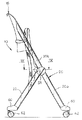
図1〜3を参照すると、参照符号10は、本発明に係る椅子を示している。椅子10は、支持構造12、シート14、及び背もたれ16を備える。支持構造12は、一対の第一棒20と一対の第二棒22を固定する端部を横切る横要素18を備える。要素18は、好ましくはアルミ合金等のような金属材料からできている。棒22は椅子10の一対の後脚を構成し、横要素18において終端する。棒20は、椅子10の前脚を形成する下部20aと、背もたれ16の支持構造の部分を形成する上部20bとを有する。
【0006】
図5及び6を参照すると、棒20,22が横要素18に固定される方法が開示されている。横要素18の各端面24には、横要素18に面する対向面に座部28を有する第一固定要素26が使用されている。座部28は棒20の一部分を受け入れるように設計されている。第一ネジ30は、棒20の穴32及び第一固定要素26の穴34を通って挿入されて、横要素18のネジ穴36と係合する。座部28の形は、横要素18に対する予めセットされた傾斜を各棒20上に与えるように画定される。第二固定要素38が棒20の外面に使用される。第二固定要素38は、棒20に面する第一固定要素26の座部28と相補的な形状の第一座部を有する。第二固定要素38は、第二棒22を受け入れるように設計され、第一棒20及び横要素18に対する予めセットされた傾斜状態で第二棒22を維持するような形状をした第二座部40を有する。第二棒22は、一対のネジ42で横要素18に固定されている。ネジ42は、第二棒22の穴44や第二固定要素38の穴46や第一固定要素26の穴48を通って延在して、横要素18のネジ穴50と係合する。組立品は、側蓋又は棒22の外側に固定されたカバー51の使用によって完成される。好ましくは、棒22の上面では、閉止要素52が使用される。
【0007】
図6〜9を参照すると、第一固定要素26は付属物54を有する。付属物54の中には、円筒形の座部56が形成されている。その中には、シート14によって動かされるピン58が、回転するように挿入される。このように、シート14が、横要素18に平行な横軸を中心に関節運動をするとともに、横要素18に関して椅子の後部に向かって移動するように、シート14は基礎構造12に接続されている。したがって、シート14は、図4に示された持ち上げられた非動作の位置と、図2に示された下げられた動作の位置との間を動くことができる。図2の下げられた位置において、シート14が横要素18の上面に寄り掛かっていることに注意することは重要である。上記横要素18は、共に結合された椅子の二つの面を保つ構造要素であることに加えて、支持の要素及びシート14の運動端又は回り止めを構成する。
【0008】
前述した固定システムによって、後脚を形成する棒22が、前脚を形成するそれぞれの棒20について縦方向に配置される。各棒22と対応する棒20との間の距離は、第二固定要素38の厚みで決定される。棒20の間での横方向の間隔は、各外側棒22の厚みに等しいか又は大きい。このように、非動作の位置に持ち上げられたシート14をそれぞれ持った同じタイプの二つの椅子は、図7に示すように、互いに対抗して、互いに縦方向に滑り落ちる。好ましくは、脚20,22の下端は、椅子間の相互に貫き合う操縦を容易にし、特に、その前にある椅子の後脚22間に前脚20aを挿入することを容易にするガイド面を有する足60を持っている。好ましくは、足60は回転輪62を持っている。
【0009】
本発明に係る椅子は、シート14を下側位置にした状態で、図8に示すようにともに積み重ねられる。
【0010】
本発明に係る椅子は、最も都合がよい方法で、すなわち互いに縦方向に滑り落ちる配置に従って、使用されていないときに積み重ねを離すか又は、同じタイプの他の椅子の上面に垂直に積み重ねる。本発明に係る椅子の構造は、椅子の様々な部品に熔接がないことによって、非常に素早く且つ容易な自動的な方法で量産化されるのに適している。
【0011】
図10〜15を参照すると、本発明に係る椅子の背もたれ16は、好ましくは、各横軸を中心に互いに独立して揺動する二つのセクションから形成されている。さらに詳しくは、背もたれ16は、下セクション64と上セクション66とを備える。背もたれの両方のセクション64,66は、休息の状態で、棒20の部分20bと整列している一対の管状部68,70を有する。図13を参照すると、背もたれの下セクション64の各管状部分68は、第一弾性戻しデバイス72によって、それぞれの棒20bに接続される。同様に、背もたれの上セクション68の各管状部分70は、第二弾性戻しデバイス74によって、下フレームセクション64の管状部分68に接続される。
【0012】
図14を参照すると、各弾性戻しデバイス72,74は、上管状部材76、タイロッド78、下管状部材80、スライド要素82、及び弾性要素84を備える。タイロッド78は、その上端で上管状部材76に連結され、その下端でスライド要素82に接続されている。弾性要素84は、スライド要素82と下管状部材80の内側の上壁との間に圧縮されてセットされた螺旋状バネからなる。バネ84の推力は、二つの管状要素76,80を接触され且つ相互に整列した位置に維持する傾向がある。二つの管状要素76,80の相互接触86,88の表面において、管状要素76,80の間で相対的に搖動する軸を画定するピン90がセットされている。ピン90の軸を中心に管状要素76,80の間で相互に搖動することによって、バネ84が圧縮される。管状要素76,80の間での相対的な傾斜の最大角度は、下管状部材80に対するスライド要素82の最大動作によって画定される。スライド要素82は、管状部材78,80の間で最も傾斜した状態で下管状部材80のエッジ94に影響を与えるように設計されているショルダー92を有する。各弾性戻しデバイス72,74は、変形可能な材料からなる保護リング96をさらに備える。保護リング96は、管状要素76,80の二つのショルダー98,100を取り囲む。図11〜13を参照すると、弾性戻しデバイス72の管状部材80は、棒20bの上端に挿入されてその内部に固定されるが、同じ弾性戻しデバイスの管状部材76は、下背もたれ要素64の管状部分に挿入されてその内部に固定される。同様に、弾性戻しデバイス74の下管状部材80は、下背もたれ要素64の管状部分68に挿入されてその内部に固定されるが、弾性戻しデバイス74の上管状部材76は、上背もたれ要素66の管状部分70に挿入されてその内部に固定される。
【0013】
図12は、背もたれ16が最も後方に傾斜した状態での弾性戻し手段72,74の位置を図示している。弾性戻しデバイス72の最大傾斜角度αは、上弾性戻しデバイス74の最大傾斜角度(βで示される)より大きい。好ましくは、最大傾斜角度αは、最大傾斜角度βのおおよそ二倍である。例えば、傾斜角度αはおおよそ12度であるが、傾斜角度βはおおよそ6度である。使用者の背中の自然な曲線の曲面と同様の曲面に応じて、背もたれの部分64,66が最も後方に傾斜した状態で配置される限り、この状態によって、使用者が最も快適になる。
【0014】
もちろん、本発明の原理を損なうことなく、構成の詳細及び実施形態は、請求項によって規定される本発明の範囲から逸脱することなく、本明細書に図示及び記載されたものを参照して十分に変形される。
【図面の簡単な説明】
【図1】 本発明に係る椅子の斜視図である。
【図2】 図1の椅子の側面図である。
【図3】 図1の椅子の正面図である。
【図4】 本発明に係る、シートが持ち上げられた位置にある椅子を示す側面図である。
【図5】 図1の矢印Vで示された部分を拡大した斜視図である。
【図6】 図5の矢印VIで示された部分を拡大した斜視図である。
【図7】 本発明に係る、縦方向に互いに立て掛けられた二つの椅子を示す。
【図8】 本発明に係る、上面に積み重ねられた二つの椅子を示す。
【図9】 図4のIX−IX線で切り取られた断面である。
【図10】 図1の矢印Xによる部分斜視面である。
【図11】 図10のXI−XI線で切り取られた断面図である。
【図12】 第二動作位置での、図11と同様の断面図である。
【図13】 図10の矢印XIIIで示された部分の拡大斜視図である。
【図14】 図13の矢印XIVで示されたデバイスの拡大斜視図である。
【図15】 図11のXV−XV線で切り取られた断面図である。
【符号の説明】
10 椅子
12 支持構造
14 シート
16 背もたれ
18 横要素
20,22 棒(脚)
28 座部
30 ネジ
32 穴
36 ネジ穴
42 ネジ
51 カバー
54 付属物
56 座部
58 ピン
60 足
72,74 弾性戻しデバイス
76 上管状部材
78 タイロッド
80 下管状部材
82 スライド要素
84 バネ(弾性要素)
90 ピン
98,100 ショルダー[0001]
BACKGROUND OF THE INVENTION
The present invention particularly relates to a chair designed to be used in a place where a conference, a meeting, a show or the like is held.
[0002]
[Prior art]
Chairs designed for this application must feature a sturdy and comfortable structure. A particularly well-understood feature of chairs designed for events such as meetings, shows, etc. is that they are stacked or leaned against each other to reduce occupied space when not in use. However, a further particularly important feature is that the chair can be mass-produced by simple and easy automatic operation without penalizing aesthetics and user comfort.
[0003]
[Problems to be solved by the invention]
In order to satisfy the above-mentioned needs, the subject of the present invention is a chair having the features which form the subject of the appended claims.
[0004]
The present invention will now be described in detail with reference to the accompanying drawings, which merely provide non-limiting examples.
[0005]
DETAILED DESCRIPTION OF THE INVENTION
1-3,
[0006]
With reference to FIGS. 5 and 6, the manner in which the
[0007]
With reference to FIGS. 6-9, the first
[0008]
With the fixing system described above, the
[0009]
The chairs according to the present invention are stacked together as shown in FIG. 8 with the
[0010]
The chairs according to the invention are separated in the most convenient way, i.e. according to an arrangement that slides longitudinally with respect to one another, when they are not in use, or they are stacked vertically on top of other chairs of the same type. The structure of the chair according to the invention is suitable for mass production in a very quick and easy automatic way by the absence of welding on the various parts of the chair.
[0011]
10 to 15, the chair back 16 according to the present invention is preferably formed of two sections that swing independently of each other about the horizontal axis. More specifically, the
[0012]
Referring to FIG. 14, each
[0013]
FIG. 12 illustrates the positions of the elastic return means 72 and 74 in a state where the
[0014]
Of course, without departing from the principles of the invention, details of construction and embodiments may be sufficiently referred to what is illustrated and described herein without departing from the scope of the invention as defined by the claims. Transformed into
[Brief description of the drawings]
FIG. 1 is a perspective view of a chair according to the present invention.
FIG. 2 is a side view of the chair of FIG.
FIG. 3 is a front view of the chair of FIG. 1;
FIG. 4 is a side view of the chair according to the present invention with the seat in the raised position.
FIG. 5 is an enlarged perspective view of a portion indicated by an arrow V in FIG.
6 is an enlarged perspective view of a portion indicated by an arrow VI in FIG.
FIG. 7 shows two chairs leaning against each other in the longitudinal direction according to the present invention.
FIG. 8 shows two chairs stacked on top according to the present invention.
9 is a cross section taken along line IX-IX in FIG. 4;
10 is a partial perspective view taken along arrow X in FIG.
11 is a cross-sectional view taken along line XI-XI in FIG.
FIG. 12 is a cross-sectional view similar to FIG. 11 at the second operating position.
13 is an enlarged perspective view of a portion indicated by an arrow XIII in FIG.
14 is an enlarged perspective view of the device indicated by arrow XIV in FIG.
15 is a cross-sectional view taken along line XV-XV in FIG.
[Explanation of symbols]
10 chairs
12 Support structure
14 seats
16 Backrest
18 Horizontal elements
20, 22 bars (legs)
28 Seat
30 screws
32 holes
36 Screw hole
42 screws
51 Cover
54 Accessories
56 Seat
58 pins
60 feet
72, 74 Elastic return device
76 Upper tubular member
78 Tie Rod
80 Lower tubular member
82 Slide elements
84 Spring (elastic element)
90 pin
98, 100 shoulder
Claims (9)
前記支持構造体は、
側端面と支持上面とを有する横要素と、
横要素の側端面に固定されるとともに、後方突出部分を有し、下寄りの位置でシートが支持上面にもたれ掛かるように、横要素に並行し且つ横要素の後方に位置している横連結軸を中心にしてシートが後方突出部分に対して連結されている対の第一固定要素と、
横要素の下方に延在して一対の前脚を形成する下部と、横要素の上方に延在して背もたれの支持体を形成する上部と、を有する、対の第一固定要素に固定される対の第一棒と、
対の第一棒に固定される対の第二固定要素と、
対の第二固定要素に固定されて一対の後脚を形成する対の第二棒と、を備えており、
第一棒の下部と上部との間の境界部分は、第一固定要素と第二固定要素との間で固定的に取り付けられており、
後脚を形成する第二棒は、前脚を形成する第一棒に関して横方向に互い違いであることを特徴とする椅子。A chair having a pair of front legs and a pair of rear legs, a seat movable between an upper position and a lower position, and a support structure for moving the backrest,
The support structure is
A transverse element having a side end face and a support top face;
A lateral connection that is fixed to the side end surface of the lateral element and has a rear projecting portion, and is positioned parallel to the lateral element and behind the lateral element so that the seat leans against the support upper surface at a lower position. A pair of first securing elements in which the seat is connected to the rearward projecting portion about the axis;
Fixed to a pair of first fixation elements having a lower portion extending below the transverse element to form a pair of front legs and an upper portion extending above the transverse element to form a back support. A pair of first sticks,
A second fixing element of the pair fixed to the first rod of the pair;
A pair of second rods secured to the pair of second securing elements to form a pair of rear legs,
The boundary portion between the lower and upper portions of the first rod is fixedly attached between the first and second fixing elements;
A chair characterized in that the second bars forming the rear legs are staggered laterally with respect to the first bars forming the front legs.
背もたれの下セクションと背もたれの上セクションとの間にセットされた対の第二弾性戻し手段と、を備えることを特徴とする、請求項3記載の椅子。A pair of first elastic return means set between the upper end of the first bar and the lower section of the backrest;
4. A chair as claimed in claim 3, characterized in that it comprises a pair of second elastic return means set between the lower section of the backrest and the upper section of the backrest.
Applications Claiming Priority (2)
| Application Number | Priority Date | Filing Date | Title |
|---|---|---|---|
| IT2001TO000940A ITTO20010940A1 (en) | 2001-10-04 | 2001-10-04 | ,,CHAIR,, |
| IT2001A000940 | 2001-10-04 |
Publications (3)
| Publication Number | Publication Date |
|---|---|
| JP2003153761A JP2003153761A (en) | 2003-05-27 |
| JP2003153761A5 JP2003153761A5 (en) | 2008-02-14 |
| JP4212326B2 true JP4212326B2 (en) | 2009-01-21 |
Family
ID=11459239
Family Applications (1)
| Application Number | Title | Priority Date | Filing Date |
|---|---|---|---|
| JP2002291250A Expired - Lifetime JP4212326B2 (en) | 2001-10-04 | 2002-10-03 | Chair |
Country Status (12)
| Country | Link |
|---|---|
| US (1) | US6742839B2 (en) |
| EP (1) | EP1300099B1 (en) |
| JP (1) | JP4212326B2 (en) |
| CN (1) | CN1243497C (en) |
| AT (1) | ATE285695T1 (en) |
| CA (1) | CA2405931C (en) |
| DE (1) | DE60202416T2 (en) |
| ES (1) | ES2233757T3 (en) |
| HK (1) | HK1055226A1 (en) |
| IT (1) | ITTO20010940A1 (en) |
| PT (1) | PT1300099E (en) |
| TW (1) | TWI230593B (en) |
Families Citing this family (49)
| Publication number | Priority date | Publication date | Assignee | Title |
|---|---|---|---|---|
| US6755468B1 (en) * | 2003-05-09 | 2004-06-29 | Oasyschair Co., Ltd. | Folding chair |
| US6969113B2 (en) * | 2003-06-03 | 2005-11-29 | Dennis Michael Krawchuk | Folding chair with metal inserts |
| DE60317798D1 (en) * | 2003-12-05 | 2008-01-10 | Pro Cord Spa | Chair with a writing tablet |
| US6863341B1 (en) * | 2004-01-12 | 2005-03-08 | Yong-Chang Wen | Foldable chair |
| JP4532130B2 (en) * | 2004-02-04 | 2010-08-25 | 株式会社岡村製作所 | Chair |
| US7066098B2 (en) | 2004-05-14 | 2006-06-27 | Hni Technologies Inc. | Nesting table with controlled pivoting movement |
| US7147286B2 (en) * | 2004-05-28 | 2006-12-12 | Hni Technologies Inc. | Versatile chair |
| US8047607B1 (en) | 2004-06-08 | 2011-11-01 | Behshad Shokouhi | Modular stackable furniture systems |
| US8454088B2 (en) | 2004-06-08 | 2013-06-04 | Chameleon Chairs LLC | Modular stackable furniture systems |
| US9527519B1 (en) | 2004-06-08 | 2016-12-27 | Chameleon Chairs, Llc | Modular stackable furniture systems |
| US7240963B2 (en) * | 2005-02-22 | 2007-07-10 | Stanley Larry S | Hand rail assembly incorporating articulating seats |
| EP1785069A1 (en) * | 2005-11-10 | 2007-05-16 | Pro-Cord S.P.A. | Nestable chair |
| US7552968B2 (en) * | 2005-12-12 | 2009-06-30 | Mity-Lite, Inc. | Feet for stacking chair |
| US20070222266A1 (en) * | 2006-03-21 | 2007-09-27 | Ditto Sales, Inc. | Nestable and stackable chair |
| US8960106B2 (en) * | 2006-05-15 | 2015-02-24 | Aichi Co., Ltd. | Desk |
| JP5301446B2 (en) * | 2006-10-04 | 2013-09-25 | フォームウェイ ファーニチャー リミテッド | Chair |
| US7410211B1 (en) * | 2007-02-07 | 2008-08-12 | Mei Chuen Lin | Folding chair with wheels |
| CN101801241B (en) | 2007-03-13 | 2013-06-05 | Hni技术公司 | Dynamic chair back lumbar support system |
| US20080315646A1 (en) * | 2007-06-21 | 2008-12-25 | Koh-Tuang Hock | Chair capable of being firmly stacked |
| US20080315645A1 (en) * | 2007-06-21 | 2008-12-25 | Koh-Tuang Hock | Chair capable of being firmly stacked |
| US7717511B2 (en) * | 2007-09-21 | 2010-05-18 | Tsung-Chieh Huang | Structure of chair capable of being stacked vertically and horizontally |
| US7827921B2 (en) * | 2008-04-30 | 2010-11-09 | Ditto Sales, Inc. | Tilting nestable table and chair set |
| US7758112B2 (en) * | 2008-10-01 | 2010-07-20 | Tsung-Chieh Huang | Foldable chair capable of being overlapped with other chairs vertically |
| US8322787B2 (en) | 2008-12-24 | 2012-12-04 | Mity-Lite, Inc. | Clamping joint for a chair |
| US8033598B2 (en) * | 2008-12-24 | 2011-10-11 | Mity-Lite, Inc. | Mesh folding chair |
| US8454093B2 (en) | 2008-12-24 | 2013-06-04 | Mity-Lite, Inc. | Mesh chair with open-end hoop |
| US8317269B2 (en) | 2008-12-24 | 2012-11-27 | Mity-Lite, Inc. | Mesh stacking chair |
| CN102333467B (en) | 2009-02-02 | 2013-09-11 | Hni技术公司 | Stacking and nesting chair |
| USD648554S1 (en) | 2009-11-04 | 2011-11-15 | Mity-Lite, Inc. | Mesh stacking chair |
| US8540315B2 (en) * | 2010-01-21 | 2013-09-24 | Pro-Cord S.P.A. | Nestable chair with seat rotation and stop arrangement |
| US8109564B2 (en) * | 2010-02-03 | 2012-02-07 | Mei Chuen Lin | Seat self-lifting device for portable chair |
| BR112012028026A2 (en) | 2010-05-05 | 2017-03-28 | Eberhard Von Huene & Ass Inc | removable and removable wall panel system |
| US9084476B2 (en) | 2010-05-18 | 2015-07-21 | Aria Enterprises, Inc. | Portable, compact folding furniture pieces |
| USD660612S1 (en) | 2010-11-16 | 2012-05-29 | Mity-Lite, Inc. | Mesh banquet chair |
| KR101188543B1 (en) * | 2010-11-19 | 2012-10-05 | 서원호 | A Chair |
| FR2972338B1 (en) * | 2011-03-07 | 2013-03-29 | Lafuma Sa | FOLDING CHAIR |
| US9289068B1 (en) | 2012-01-25 | 2016-03-22 | Chameleon Chairs LLC | Modular stackable stool systems |
| JP6262937B2 (en) * | 2012-05-31 | 2018-01-17 | 株式会社イトーキ | Nestable chair |
| CN105101845B (en) | 2013-03-15 | 2018-11-09 | Hni技术公司 | The chair of backrest bending with triggering |
| GB2526802B (en) * | 2014-06-02 | 2016-10-12 | Davidhugh Ltd | Seat recline mechanism, adjustable seating assembly, and method |
| USD743180S1 (en) | 2014-10-15 | 2015-11-17 | Hni Technologies Inc. | Chair |
| US9801470B2 (en) | 2014-10-15 | 2017-10-31 | Hni Technologies Inc. | Molded chair with integrated support and method of making same |
| JP6649042B2 (en) * | 2015-11-09 | 2020-02-19 | 株式会社イトーキ | Chair |
| ITUB20159640A1 (en) * | 2015-12-22 | 2017-06-22 | Pro Cord Spa | FOLDING CHAIR |
| ES2723604A1 (en) * | 2018-02-22 | 2019-08-29 | Figueras Seating Solutions S L | FOLDING CHAIR (Machine-translation by Google Translate, not legally binding) |
| IT201900011166A1 (en) * | 2019-07-08 | 2021-01-08 | Pro Cord Spa | FLEXIBLE BACKREST FOR A FOLDING CHAIR AND FOLDING CHAIR INCLUDING THIS BACKREST |
| KR102057897B1 (en) * | 2019-07-19 | 2019-12-20 | 주식회사 듀오백 | Assembly type chair |
| JP7458739B2 (en) * | 2019-10-18 | 2024-04-01 | 株式会社オカムラ | Load-bearing structures and fixtures |
| IT202200018999A1 (en) * | 2022-09-16 | 2024-03-16 | Pagotto S R L – Socio Unico | “Rotary joint” |
Family Cites Families (16)
| Publication number | Priority date | Publication date | Assignee | Title |
|---|---|---|---|---|
| US529645A (en) * | 1894-11-20 | Folding chair | ||
| US556418A (en) * | 1896-03-17 | Folding chair | ||
| US2011067A (en) * | 1932-06-07 | 1935-08-13 | K M Mckee | Tubular metal chair |
| CA877743A (en) * | 1969-09-20 | 1971-08-10 | Anonima Castelli S.A.S. | Three position folding seat |
| US3982785A (en) * | 1974-07-29 | 1976-09-28 | Center For Design Research And Development | Chair |
| US4157203A (en) * | 1977-05-09 | 1979-06-05 | Center For Design Research And Development N.V. | Articulated double back for chairs |
| US4580836A (en) * | 1982-12-23 | 1986-04-08 | Intercollection Development S.A. Gyrenmoos | Chair |
| US4549764A (en) * | 1983-09-14 | 1985-10-29 | K. L. Spring & Stamping Corporation | Flexible chair back |
| DE3570973D1 (en) * | 1984-10-23 | 1989-07-20 | Protoned Bv | Chair |
| US4603904A (en) * | 1985-08-12 | 1986-08-05 | Shelby Williams Industries, Inc. | Chair with articulated, flexible spring backrest |
| US4869552A (en) * | 1988-09-14 | 1989-09-26 | Shelby Williams Industries, Inc. | Flexible backrest assembly for a chair |
| IT1270378B (en) * | 1993-05-27 | 1997-05-05 | Pro Cord Srl | FOLDING CHAIR WITH OSCILLATING BACKREST |
| DK172786B1 (en) * | 1995-05-02 | 1999-07-19 | Haag As | Furniture with two adjacent swivel supports |
| EP0995376A1 (en) * | 1998-10-22 | 2000-04-26 | Protoned B.V. | Chair with backrest |
| US6481789B1 (en) * | 1999-06-18 | 2002-11-19 | Center For Design Research And Development N.V. | Stackable chair |
| US6478379B1 (en) * | 2000-06-07 | 2002-11-12 | Center For Design Research And Development N.V. | Chair |
-
2001
- 2001-10-04 IT IT2001TO000940A patent/ITTO20010940A1/en unknown
-
2002
- 2002-09-26 AT AT02021537T patent/ATE285695T1/en not_active IP Right Cessation
- 2002-09-26 ES ES02021537T patent/ES2233757T3/en not_active Expired - Lifetime
- 2002-09-26 EP EP02021537A patent/EP1300099B1/en not_active Expired - Lifetime
- 2002-09-26 DE DE60202416T patent/DE60202416T2/en not_active Expired - Fee Related
- 2002-09-26 PT PT02021537T patent/PT1300099E/en unknown
- 2002-09-30 CA CA002405931A patent/CA2405931C/en not_active Expired - Fee Related
- 2002-09-30 US US10/262,416 patent/US6742839B2/en not_active Expired - Fee Related
- 2002-09-30 TW TW091122573A patent/TWI230593B/en not_active IP Right Cessation
- 2002-10-03 JP JP2002291250A patent/JP4212326B2/en not_active Expired - Lifetime
- 2002-10-04 CN CNB021547629A patent/CN1243497C/en not_active Expired - Fee Related
-
2003
- 2003-10-20 HK HK03107596A patent/HK1055226A1/en not_active IP Right Cessation
Also Published As
| Publication number | Publication date |
|---|---|
| CA2405931A1 (en) | 2003-04-04 |
| JP2003153761A (en) | 2003-05-27 |
| PT1300099E (en) | 2005-04-29 |
| CA2405931C (en) | 2009-12-15 |
| US6742839B2 (en) | 2004-06-01 |
| DE60202416D1 (en) | 2005-02-03 |
| CN1411769A (en) | 2003-04-23 |
| EP1300099B1 (en) | 2004-12-29 |
| EP1300099A3 (en) | 2003-05-14 |
| ATE285695T1 (en) | 2005-01-15 |
| CN1243497C (en) | 2006-03-01 |
| ITTO20010940A1 (en) | 2003-04-04 |
| EP1300099A2 (en) | 2003-04-09 |
| DE60202416T2 (en) | 2005-12-08 |
| TWI230593B (en) | 2005-04-11 |
| US20030090137A1 (en) | 2003-05-15 |
| HK1055226A1 (en) | 2004-01-02 |
| ITTO20010940A0 (en) | 2001-10-04 |
| ES2233757T3 (en) | 2005-06-16 |
Similar Documents
| Publication | Publication Date | Title |
|---|---|---|
| JP4212326B2 (en) | Chair | |
| US6517156B1 (en) | Backrest structure for a leisure chair | |
| NZ237726A (en) | Flexible stacking chair with one piece frame and pivotally connected seat and back | |
| JP2002136390A (en) | Back plate for chair | |
| KR930700032A (en) | High Density Stackable Flexible Chair | |
| FR2654316A1 (en) | ||
| US6883863B2 (en) | Chair and table assembly | |
| WO2008004583A1 (en) | Reclining chair structure | |
| JP4950486B2 (en) | Chair | |
| JP5567402B2 (en) | Chair | |
| JP3046819U (en) | sofa | |
| JP4520622B2 (en) | Seat mounting device in chair | |
| JPH07194454A (en) | Chair | |
| KR100809265B1 (en) | A chair with a waist supporting department | |
| JP4491318B2 (en) | Chair backrest device | |
| JP5616134B2 (en) | Chair | |
| KR200165088Y1 (en) | Rocking chair | |
| JP4694707B2 (en) | Seat front / rear position adjustment device | |
| JP3519827B2 (en) | Chair | |
| JP4486465B2 (en) | Chair backrest mounting structure | |
| JP2000245574A (en) | Bed | |
| JP2001078849A (en) | Sofa | |
| JPS6239740Y2 (en) | ||
| JP3086095U (en) | Chair | |
| JP3986745B2 (en) | Chair |
Legal Events
| Date | Code | Title | Description |
|---|---|---|---|
| A621 | Written request for application examination |
Free format text: JAPANESE INTERMEDIATE CODE: A621 Effective date: 20050412 |
|
| A521 | Request for written amendment filed |
Free format text: JAPANESE INTERMEDIATE CODE: A523 Effective date: 20071220 |
|
| A871 | Explanation of circumstances concerning accelerated examination |
Free format text: JAPANESE INTERMEDIATE CODE: A871 Effective date: 20071220 |
|
| A975 | Report on accelerated examination |
Free format text: JAPANESE INTERMEDIATE CODE: A971005 Effective date: 20080110 |
|
| A131 | Notification of reasons for refusal |
Free format text: JAPANESE INTERMEDIATE CODE: A131 Effective date: 20080219 |
|
| A521 | Request for written amendment filed |
Free format text: JAPANESE INTERMEDIATE CODE: A523 Effective date: 20080515 |
|
| A131 | Notification of reasons for refusal |
Free format text: JAPANESE INTERMEDIATE CODE: A131 Effective date: 20080617 |
|
| A521 | Request for written amendment filed |
Free format text: JAPANESE INTERMEDIATE CODE: A523 Effective date: 20080916 |
|
| TRDD | Decision of grant or rejection written | ||
| A01 | Written decision to grant a patent or to grant a registration (utility model) |
Free format text: JAPANESE INTERMEDIATE CODE: A01 Effective date: 20081014 |
|
| A01 | Written decision to grant a patent or to grant a registration (utility model) |
Free format text: JAPANESE INTERMEDIATE CODE: A01 |
|
| A61 | First payment of annual fees (during grant procedure) |
Free format text: JAPANESE INTERMEDIATE CODE: A61 Effective date: 20081028 |
|
| FPAY | Renewal fee payment (event date is renewal date of database) |
Free format text: PAYMENT UNTIL: 20111107 Year of fee payment: 3 |
|
| R150 | Certificate of patent or registration of utility model |
Ref document number: 4212326 Country of ref document: JP Free format text: JAPANESE INTERMEDIATE CODE: R150 Free format text: JAPANESE INTERMEDIATE CODE: R150 |
|
| FPAY | Renewal fee payment (event date is renewal date of database) |
Free format text: PAYMENT UNTIL: 20111107 Year of fee payment: 3 |
|
| FPAY | Renewal fee payment (event date is renewal date of database) |
Free format text: PAYMENT UNTIL: 20121107 Year of fee payment: 4 |
|
| R250 | Receipt of annual fees |
Free format text: JAPANESE INTERMEDIATE CODE: R250 |
|
| FPAY | Renewal fee payment (event date is renewal date of database) |
Free format text: PAYMENT UNTIL: 20121107 Year of fee payment: 4 |
|
| FPAY | Renewal fee payment (event date is renewal date of database) |
Free format text: PAYMENT UNTIL: 20131107 Year of fee payment: 5 |
|
| R250 | Receipt of annual fees |
Free format text: JAPANESE INTERMEDIATE CODE: R250 |
|
| R250 | Receipt of annual fees |
Free format text: JAPANESE INTERMEDIATE CODE: R250 |
|
| R250 | Receipt of annual fees |
Free format text: JAPANESE INTERMEDIATE CODE: R250 |
|
| R250 | Receipt of annual fees |
Free format text: JAPANESE INTERMEDIATE CODE: R250 |
|
| R250 | Receipt of annual fees |
Free format text: JAPANESE INTERMEDIATE CODE: R250 |
|
| R250 | Receipt of annual fees |
Free format text: JAPANESE INTERMEDIATE CODE: R250 |
|
| R250 | Receipt of annual fees |
Free format text: JAPANESE INTERMEDIATE CODE: R250 |
|
| R250 | Receipt of annual fees |
Free format text: JAPANESE INTERMEDIATE CODE: R250 |
|
| R250 | Receipt of annual fees |
Free format text: JAPANESE INTERMEDIATE CODE: R250 |
|
| R250 | Receipt of annual fees |
Free format text: JAPANESE INTERMEDIATE CODE: R250 |
|
| EXPY | Cancellation because of completion of term |