JP3625342B2 - Disc cartridge - Google Patents
Disc cartridge Download PDFInfo
- Publication number
- JP3625342B2 JP3625342B2 JP25993596A JP25993596A JP3625342B2 JP 3625342 B2 JP3625342 B2 JP 3625342B2 JP 25993596 A JP25993596 A JP 25993596A JP 25993596 A JP25993596 A JP 25993596A JP 3625342 B2 JP3625342 B2 JP 3625342B2
- Authority
- JP
- Japan
- Prior art keywords
- shutter
- case
- spring
- window
- closed position
- Prior art date
- Legal status (The legal status is an assumption and is not a legal conclusion. Google has not performed a legal analysis and makes no representation as to the accuracy of the status listed.)
- Expired - Fee Related
Links
Images


Description
【0001】
【発明の属する技術分野】
この発明は、記録媒体としての光ディスクを収納したディスクカートリッジに関し、特に、両方向に開閉可能なシャッタを備えたディスクカートリッジに関する。
【0002】
【従来技術】
近年、フロッピーディスクに変わる大容量の記録媒体として、光磁気(MO)記録タイプの90mm光ディスクが普及している。また、同じ90mmの書換え可能な光ディスクとして、両面の使用が可能で更に大容量化が可能な相変化型(PC)タイプの光ディスク、およびこれを備えた光ディスクドライブも開発されている。
【0003】
PCタイプの光ディスクは、その特徴を生かすために、縦横の寸法を初めとする基本部分は、90mmのMOタイプのディスクと同じであるものの、主に厚さサイズとシャッタの開閉機構を独自なものとする専用のカートリッジが用意されている。
【0004】
通常、ディスクカートリッジは、光ディスクを収納した偏平な矩形状のケースを備え、このケースの両面には、光ディスクの一部およびハブを露出するための窓部が形成されている。また、このケースには、窓部を開閉するための摺動自在なシャッタが設けられている。
【0005】
また、近年、この種のディスクカートリッジとして、例えば、特開昭63−119081号公報、特開昭63−94487号公報に開示されているような、窓部の左右両側へ開閉可能なシャッタを備えたいわゆる両開き方式のディスクカートリッジが提案されている。
【0006】
この両開き方式のディスクカートリッジは、シャッタの両側に設けられた一対のシャッタばねを有し、シャッタはこれらのばねによりを窓部を閉塞した閉塞位置に保持されている。各シャッタばねは、ケースに固定された一端とシャッタに固定された他端と、を有している。また、シャッタには、所定の間隔を置いて2つの開口が形成されている。そして、シャッタばねの付勢力に抗してシャッタをいずれかの方向へ摺動させることにより、シャッタの一方の開口がケースの窓部に対抗し、窓部が開放される。
【0007】
更に、他のタイプの両開き式ディスクカートリッジとして、ケースの幅方向全長に亘って設けられたガイドシャフトと、ガイドシャフトに摺動自在に取り付けられた一対のスライダと、これらのスライダを互いに連結した引っ張りばねと、各スライダの摺動を規制するようにケースの内壁に設けられた突起と、を備えたものが提供されている。
【0008】
このディスクカートリッジによれば、シャッタを一方へ開放する際には、一方のスライダがシャッタとともにガイドシャフト上を移動し、他方のスライダは突起によって一方向への移動が規制される。それにより、シャッタは、引っ張りばねの付勢力を受けた状態で開放位置に移動し、シャッタに加えられていた開放力が解除されると、引っ張りばねの付勢力により、ケースの窓部を閉じる閉塞位置に復帰される。
【0009】
【発明が解決しようとする課題】
しかしながら、上述した一対のシャッタばねを有するディスクカートリッジにおいては、シャッタばねの付勢力のばらつき等によりシャッタを閉塞位置に正確に保持することが困難となる。また、シャッタの開放動作時、両方のシャッタばねが伸縮動作するため、シャッタの移動ストロークも大きくとることができない。
【0010】
また、ガイドシャフト、スライダ等を備えたタイプのディスクカートリッジにおいては、その部品点数が多く製造コストが高価になるとともに、構造が複雑で組立性が比較的困難となり、特に、大量生産における自動組立には適さない。
【0011】
この発明は以上の点に鑑みなされたもので、その目的は、構造が簡単で自動組立が可能であるとともに、シャッタを閉塞位置に確実に保持することが可能なディスクカートリッジを提供することにある。
【0012】
【課題を解決するための手段】
上記目的を達成するため、この発明の態様に係るディスクカートリッジは、ディスク状の記録媒体を収納しているとともに、上記記録媒体の一部を露出した窓部と、上記窓部の形成された2つの平行な主面と、前端面と、互いに平行な2つの側面とを有する偏平な矩形状のケースと、上記窓部を閉塞する閉塞位置と、上記窓部の両側に位置しそれぞれ上記窓部を開放する2つの開放位置と、へ移動自在に上記ケースに取り付けられたシャッタと、上記ケース内で上記シャッタの両側に配設され、それぞれ上記シャッタを上記閉塞位置に向けて付勢し上記閉塞位置に保持した一対のシャッタばねと、上記シャッタの移動をガイドするガイド手段と、を備えている。
【0013】
上記ケースは、上記窓部の両側に形成されそれぞれ上記シャッタばねを収容したばね収容部と、上記ケースの前端面に開口しているとともにそれぞれ上記ばね収容部に連通し上記シャッタばねを挿通可能な2つの開口部と、上記開口部間に位置し上記窓部に対向したブリッジ部と、を有し、上記シャッタばねは、それぞれケースに固定された固定端と、上記シャッタが上記閉塞位置にある際に上記ケースおよびシャッタと離脱可能に係合する可動端と、を有し、上記シャッタは、上記閉塞位置から一方の開放位置に向けて移動した際、上記一方の開放位置側に設けられたシャッタばねの可動端を上記固定端側に押圧して上記ケースから離間させるとともに、他方の開放位置側に設けられたシャッタばねの可動端から離間する。
【0014】
上記ガイド手段は、上記ブリッジ部に形成された第1の部分と、上記各ばね収容部内において上記ケースの内面に形成されているとともに上記第1の部分と直線的に整列した一対の第2の部分とを有し、上記前端面に沿って延びるガイド溝と、上記シャッタに設けられ上記シャッタの移動に応じて上記ブリッジ部上および各ばね収容部内を移動するガイド突起と、を備え、上記ガイド突起は、上記ブリッジ部上を移動する際に上記第1の部分と係合する第1の突部と、上記ばね収容部内を移動する際に上記第2の部分と係合する第2の突部と、を有していることを特徴としている。
【0018】
上記構成のディスクカートリッジによれば、組立時、シャッタをケースに装着した後、ケースの開口部を通して各シャッタばねをばね収容部内に挿入することにより、一対のシャッタばねを所定位置に装着することができる。
【0019】
また、閉塞位置に移動した状態において、シャッタは一対のシャッタばねにより付勢されて閉塞位置に保持される。その際、各シャッタばねの可動端は、シャッタに係合するとともにケースにも係合して付勢力が規制され、シャッタが過度の付勢されることが防止される。
【0020】
シャッタの開放時、その開放側に設けられたシャッタばねの可動端は、シャッタに押されてケースから離間し、シャッタと係合した状態で固定端側に変位する。これに対して、他方のシャッタばねの可動端は、ケースと係合した状態に保持され、シャッタから離間する。それにより、シャッタは、一方のシャッタばねのみの付勢力を受けた状態で開放位置へ移動することができる。
【0026】
シャッタの開閉動作において、シャッタに設けられたガイド突起は、ブリッジ部上を移動する際、第1の突部をガイド溝の第1の部分に係合させることによりシャッタの移動をガイドし、各ばね収容部内を移動する際、第2の突部をケース内面に形成されたガイド溝の第2の部分に係合させることによりシャッタの移動をガイドする。従って、いずれの移動位置においても、ガイド突起によってシャッタの移動を確実にガイドすることが可能となる。
【0027】
【発明の実施の形態】
以下、図面を参照しながらこの発明の実施の形態に係るディスクカートリッジについて詳細に説明する。
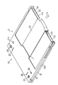
まず、全体の構成について概略的に説明すると、図1ないし図3に示すように、本実施例に係るディスクカートリッジ10は、情報記録媒体として、例えば、両面に記録再生面を有する光ディスク14を収納した偏平な矩形状のケース12を備えている。このケース12は、一対のハーフケース13を接合することにより形成されている。
【0028】
ケース12の上面および下面、つまり、2つの主面には、光デイスク14へのアクセス用の窓部16がそれぞれ形成されて互いに対向している。各窓部16は、それぞれケース12のほぼ中央から、ディスクカートリッジ10の挿入方向Aに向かって、ケース12の前端面12a近傍まで延びている。
【0029】
ケース12内に収納された光ディスク14の中心部には、中心孔21の形成されたハブ18が取り付けられている。そして、ハブ18および光ディスク14の両面の一部は、窓部16を通して露出している。
【0030】
ケース12には、窓部16を開閉する両面一体型のシャッタ22が摺動自在に設けられている。シャッタ22は、断面U字形状に形成され、ケース12の前端面12a側からケース12の両面側を挟むようにして取り付けられている。そして、シャッタ22は、図1に示すように、窓部16を閉塞する閉塞位置と、図3に実線および2点鎖線でそれぞれ示すように、閉塞位置の両側に位置しそれぞれ窓部16を開放する2つの開放位置と、の間をケース12の前端面12aと平行な方向に沿って摺動可能となっている。そして、後述するように、シャッタ22は、ケース12内で窓部16の両側に配設された2つのシャッタばね8a、8bにより閉塞位置に向かって常時付勢されている。
【0031】
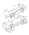
次に、ディスクカートリッジ10の各部の構成について詳細に説明する。 図1および図2に示すように、ケース12の一対のハーフケース13は一部を除いて互いに等しい形状および構造を有し、表裏を逆にした状態で内面を向い合わせて接合されている。各ハーフケース13は、アクセス用の窓部16を有している。また、ハーフケース13の表面の内、シャッタ22が摺動する領域は、浅い矩形状の凹所15として形成され、窓部16もこの凹所内に形成されている。また、ハーフケース13は、凹所15の後端中央部から窓部16の近傍まで突出した抜け止め用の突部17を有し、この突部17は、後述するように、シャッタ22の自由端部と係合してシャッタを凹所15内に保持する。
【0032】
各ハーフケース13の前端中央部には、窓部16を横切って延びるブリッジ部21が形成され、窓部の前端と対向している。一方のハーフケース13のブリッジ部21の内面には一対の嵌合孔23が形成され、他方のハーフケース13のブリッジ部21には、嵌合孔23に嵌合する図示しない一対の突起が設けられている。一対のハーフケース13は、一方に嵌合孔23、他方に突起が設けられている点を除いて、ほぼ同様の構成を有している。
【0033】
各ハーフケース13の後端側両角部には、図示しないライトプロテクト切換用の操作駒が摺動自在に嵌合される取付孔20、図示しない光ディスクドライブへのディスクカートリッジの装填時、光ディスクドライブ側に設けられた凸部が挿通されることにより、光ディスクカートリッジを光ディスクドライブに対して位置きめするための一対の基準位置決め24、および図示しない光ディスクドライブへのディスクカートリッジの装填を検出するための検出孔26がそれぞれ形成されている。
【0034】
図2および図4からよく分かるように、ハーフケース13の内面には、ハーフケースの外縁の内、前端部を除くほぼ全周に亘って所定高さのリブ13aが形成され、ケース12の両側壁および後壁を構成している。また、ハーフケース13の内面には、光デイスク14収納用の空間部を構成するための円環状のリブ13bがー体に形成されている。
【0035】
窓部16の前端部の両側には、リブ13a、13bおよびブリッジ部21により、それぞれシャッタばね8を収容するための一対のばね収容部30が形成されている。各ばね収容部30は、ケース12の前端面12aに開口した開口部32を有し、これらの開口部32はブリッジ部21の両側に位置している。
【0036】
ハーフケース13の一方の側壁内面には固定ばね受け34が突設され、開口部32の近傍でばね収容30内に位置している。固定ばね受け34は、フック状に形成されているとともに、ハーフケース13の側壁内面側からばね収容部30側かつ後方に向かって傾斜した傾斜面34aを有している。
【0037】
また、他方のばね収容部30内においてブリッジ部21の近傍には、突部36が設けられ、この突部の上面、つまり、一対のハーフケース13を接合した際に互いに対向する側の面には、開口部32側かつハーフケース13の内面側に向かって傾斜したガイド面36aが形成されている。ガイド面36aは、後述するように、シャッタばね8が変形位置から初期位置、つまり、シャッタ22が閉塞位置にある時の位置、へ戻る際に、シャッタばねのアームを所定の位置にガイドする。
【0038】
図2、図4および図5に示すように、ブリッジ部21の長手方向両端部には、左右一対の係止ばね受け38がそれぞれ形成されている。各係止ばね受け38は、それぞれ対向するばね収容部30に向けて開口した凹所により形成されているとともに、ばね収容部30側かつハーフケース13の後方に向かって傾斜した傾斜面38aを有している。また、係止ばね受け38と、これらに対向した固定ばね受け34とは、シャッタ22を開放位置に移動させた際に両者38、34の干渉を防止できる程度だけ、互いにハーフケース13の前後方向、つまり、挿入方向Aに僅かにずれて形成されている。
【0039】
また、ハーフケース13には、その前端面12aに沿って延びるガイド溝40が形成され、この前端面の近傍に位置している。このガイド溝40は、シャッタ22の摺動をガイドするために設けられたもので、ブリッジ部21の外面に形成された第1の部分40aと、ハーフケース13の内面に形成されそれぞればね収容部30内に位置した一対の第2の部分40bと、で構成されている。
【0040】
第1の部分40aは、ブリッジ部21の長手方向全長に亘って伸び、その両端は、それぞれ対応するばね収容部30に連通している。また、各第2の部分40bは、第1の部分40aと直線状に整列して形成されているとともに、ハーフケース13の側壁からブリッジ部21まで伸び、第1の部分40aの端部に連通している。
【0041】
なお、ブリッジ部21は、その外面がハーフケース12の他の部分の外面よりも低いレベルに位置し、ブリッジ部21の先端部両端とばね収容部30との境界部分には、ガイド溝40まで延びるスリット42が形成されている。そして、ガイド溝40の第1および第2の部分40a、40bの端部は、このスリット42を介して上下逆向きに対向している。
【0042】
ブリッジ部21の先端部内面には、ハーフケース13の前端面12aに沿って延びているとともに前端面に開口した移動溝44が形成されている。また、ブリッジ部21の外面には、その前端からガイド溝40の第1の部分40a近傍まで延びる一対の装着ガイド溝46が形成されている。各装着ガイド溝46は、ガイド溝40a側からブリッジ部21の先端側に向かって傾斜して形成されている。
【0043】
上記のように構成された一対のハーフケース13は、互いに内面を向い合わせた状態で突き合わされて互いに接合される。同時、一方のブリッジ部21に形成された嵌合孔23に他方のブリッジ部に形成された突起が弾性的に嵌合され、ハーフケース13同志の接合状態が維持される。
【0044】
ハーフケース13同志が接合された状態において、図6および図7に示すように、ブリッジ部21を挟んでその両側には、ばね収容部30が形成されている。ケース12の左右両側壁内面には固定ばね受け34が設けられ、それぞれ対応するばね収容部30内に突出している。また、各ばね収容部30内において、ブリッジ部21の近傍には、シャッタばねのアームをガイドする傾斜したガイド面36aが設けられている。
【0045】
2つのブリッジ部21にそれぞれ形成された係止ばね受け38は、ブリッジ部の各端部において互いに整列して位置し、対応するばね収容部30に対向している。また、ブリッジ部21に形成された移動溝44の各端部は、互いに対向した2つの係止ばね受け38間を通って延び、ばね収容部30に連通している。更に、ブリッジ部21に形成された装着ガイド溝46は、他方のブリッジ部に形成された装着ガイド溝46とそれぞれ対向して配置されている。
【0046】
図2および図8に示すように、シャッタ22は、それぞれケース12の窓部16を閉塞可能な大きさを有する細長い矩形状に形成された一対の遮蔽板22aと、これらの遮蔽板を連結した連結板22b、を有している。遮蔽板22aは所定の間隔を置いて互いに平行に対向しているとともに、連結板22bは遮蔽板と直交して延び遮蔽板の一端同志を連結している。
【0047】
図2、図8および図9に示すように、シャッタ22の連結板22bは、その幅方向中央部分に突出部50を有し、この突出部により段部51が形成されている。これらの段部51には、シャッタ22をスライドさせるための図示しない光ディスクドライブ側のシャッタ開閉機構の開閉ピン70(図21参照)が係合する。
【0048】
また、シャッタ22は、左右一対づつ設けられたガイド突起52a、52bと、一対の可動ばね受け54と、を備えている。すなわち、連結板22bの幅方向一端部の内面に一対のガイド突起52a、52b、および一方の可動ばね受け54が設けられ、連結板22bの幅方向他端部の内面に他の一対のガイド突起52a、52b、および他方の可動ばね受け54が設けられている。
【0049】
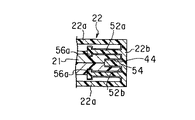
ガイド突起52a、52bは板状に形成され、連結板22bの内面から遮蔽板22aと平行に突出しているとともに、ケース12のブリッジ部21の厚さとほぼ等しい距離だけ離間して互いに対向している。ガイド突起52aは、その延出端からガイド突起52b側へ直角に突出した突部56a(第1の突部)と、延出端から遮蔽板22b側へ直角に突出した突部56b(第2の突部)と、有し、これらの突部は、連結板22bと平行な方向、つまり、シャッタ22の摺動方向に延びている。それにより、ガイド突起52aは、全体としてほぼT字状の断面形状に形成されている。
【0050】
同様に、ガイド突起52bは、その延出端からガイド突起52a側へ直角に突出した突部56a(第1の突部)と、延出端から遮蔽板22b側へ直角に突出した突部56b(第2の突部)と、有し、これらの突部は、連結板22bと平行な方向、つまり、シャッタ22の摺動方向に延びている。それにより、ガイド突起52bは、全体としてほぼT字状の断面形状に形成されている。
【0051】
また、各可動ばね受け54も板状に形成され、連結板22bの内面から遮蔽板22aと平行に突出しているとともに、ガイド突起52a、52b間に位置している。各可動ばね受け54は、板状の突起形成された凹所54aを有し、この凹所は、前述したケース12の係止ばね受け38とほぼ同一の寸法および形状に形成されている。
【0052】
上記構成のシャッタ22は、樹脂により一体成形されている。連結板22bの厚さd1は、各遮蔽板22aの厚さd2の約2倍に設定されている。また、連結板22bの強度を向上させるため、突出部50の内側には、連結板22bの長手方向に延びる2本のリブ58が一体に形成されている。また、ガイド突起52a、52b、および可動ばね受け54の強度および位置精度を向上させるため、これらの基端部には肉盛り59がされている。
【0053】
更に、連結板22bの突出部50の内面には、凹所60が形成されている。この凹所60は、シャッタ22を射出成形する際のゲート位置Gと対向しており、射出成形時の樹脂の流れを均一化するように作用する。
【0054】
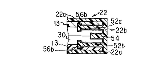
上記のように構成されたシャッタ22は、図2に示すように、遮蔽板22aの自由端をケース12の前端面12a側から矢印E方向に押し込むことによりケース12に装着される。この際、シャッタ22のガイド突起52a、52bをブリッジ部21に形成された装着ガイド溝46に位置合わせした状態で押し込む。それにより、各対のガイド突起52a、52bは、ブリッジ部21を上下から挟んだ状態で装着ガイド溝46に沿って移動する。
【0055】
シャッタ22を更に矢印E方向へ押し込むことにより、ガイド突起52a、52bは、その内側の突部56aがブリッジ部21に形成されたガイド溝40の第1の部分40aに係合し、連結板22bはケース12の前端面12aと隣接対向する。連結板22bの内面から突出した一対の可動ばね受け54は、ブリッジ部21の先端面に形成された移動溝44内に摺動自在に挿入される。
【0056】
また、遮蔽板22aはケース12の各上面上を移動し、その自由端は、ケース12の各表面に形成された凹所15の底面と、抜け止め用の突部17との間に挿入され保持される。以上の動作により、シャッタ22がケース12に取り付けられる。
【0057】
図10に示すように、シャッタ22が閉塞位置にある状態において、ケース12の2つの窓部16は、シャッタの遮蔽板22aによってそれぞれ閉塞される。各遮蔽板22aの幅は、窓部16の幅よりも僅かに大きく形成され、遮蔽板の両側縁部は、ケース12の上面壁とオーバーラップしている。
【0058】
また、図10および図11に示すように、シャッタ22の閉塞位置において、一対の可動ばね受け54の凹所54aは、ケース12のブリッジ部21の両端部に設けられた係止ばね受け38とそれぞれ整列して位置する。更に、互いに整列したこれらの可動ばね受け54、および係止ばね受け38は、シャッタ22とケース12上面壁とのオーバラップ領域60内に位置するように設けられている。
【0059】
図10および図12に示すように、シャッタ22の閉塞位置におて、シャッタのガイド突起52a、52bは、ケース12のブリッジ部21を両側から挟持している。また、ガイド突起52a、52bの内側の突部56aがそれぞれガイド溝40の第1の部分40aに摺動自在に係合している。すなわち、ガイド突起52a、52bは、ブリッジ部21上を移動する間、その内側の突部56aが第1の部分40a内を摺動することにより、シャッタ22の移動をガイドする。
【0060】
一方、図13に示すように、シャッタ22が閉塞位置から一方の開放位置へ移動されると、シャッタの両遮蔽板22aはそれぞれ窓部16から外れて窓部を開放する。この際、シャッタ22の可動ばね受け54は、ブリッジ部21の移動溝44から外れて開放側のばね収容部30内に移動する。
【0061】
また、シャッタ22のガイド突起52a、52bは、図14および図15に示すように、突部56aがガイド溝40の第1の部分40a内を摺動した後、それぞれスリット42を通って開放側のばね収容部30内へ移動する。その際、ガイド突起52a、52bの突部56aは第1の部分40aから外れ、代わって外側の突部56bがガイド溝40の第2の部分40bに係合する。以後、シャッタ22が開放位置に到達するまで、ガイド突起52a、52bの突部56bは第2の部分40b内を移動する。
【0062】
すなわち、ガイド突起52a、52bは、ばね収容部30内を移動する間、その外側の突部56bがばね収納部に設けられた第1の部分40b内を摺動することにより、シャッタ22の移動をガイドする。
【0063】
図2、図16ないし図18に示すように、ケース12の窓部16の両側に形成されたばね収容部30内に収納される一対のシャッタばね8は、同一の構造を有するものを点対称に配置して用いている。すなわち、各シャッタばね8は、コイル部8aと、コイル部の両端からほぼ相反する方向に延出した2つのアーム9a、9bと、を有している。一方のアーム9aの先端部はコイル部8a側に直角に折曲げられて固定端11aを形成している。また、他方のアーム9bの先端部は、コイル部8a側に直角に折曲げられて可動端11bを形成している。
【0064】
上記構成のシャッタばね8は、シャッタ22を閉塞位置に保持した状態で、ケース12の前端面12aに開口した開口部32からばね収容部30内にそれぞれ装着される。すなわち、まず、シャッタ22を閉塞位置に移動させ、シャッタ22の可動ばね受け54とブリッジ部21に形成された係止ばね受け38とを互いに整列させる。この状態で、各シャッタばね8の一対のアーム9a、9bを互いに接近する方向に多少弾性変形させた後、コイル部8側から開口部32を通してばね収容部30内に挿入する。
【0065】
続いて、シャッタばねの固定端11aをケース12に形成された固定ばね受け34のガイド面34aに当接させ、可動端11bを互いに整列した可動ばね受け54および係止ばね受け38のガイド面38aに当接させる。この状態で、アーム9a、9bに加えていた押圧力を解除すると、アーム9a、9bは自身の弾性により互いに離間する方向に移動する。その際、シャッタばね8の固定端11aおよび可動端11bは、それぞれガイド面34a、38aに沿って移動し、固定端11aは固定ばね受け34に係合し、可動端11bはブリッジ部21の係止ばね受け38およびシャッタ22の可動ばね受け54に係合する。
【0066】
以上の操作により、一対のシャッタばね8の装着が終了する。図16ないし図18に示すように、シャッタ22が閉塞位置にある状態において、シャッタの各可動ばね受け54はケース12の対応する係止ばね受け38と整列した状態にあり、各シャッタばね8の可動端11bも可動ばね受け54および係止ばね受け38に係合している。これにより、シャッタ22は、2つのシャッタばね8によって両側から付勢され閉塞位置に保持される。
【0067】
この場合、各シャッタばね8の可動端11bは、可動ばね受け54に加えてケース12の係止ばね受け38にも係合していることから、シャッタばね8からシャッタ22に過度の付勢力が作用することが防止され、シャッタ22は、シャッタばね8の予圧力によって閉塞位置に保持される。従って、製造のばらつき等によって2つのシャッタばね8の付勢力にばらつきがある場合でも、これらシャッタばね8によってシャッタ22を閉塞位置に正確に保持することができる。
【0068】
一方、図19ないし図21に示すように、例えば、図示しない光ディスクドライブ側のシャッタ開閉機構の開閉ピン70がケース12の前端面に沿って移動しシャッタ22の段部51に係合することにより、シャッタ22が閉塞位置からいずれかの開放位置に移動されると、シャッタ22の可動ばね受け54の内、シャッタ開放側に位置した可動ばね受け54は、ケース12の係止ばね受け38と整列した位置からシャッタ開放側のばね収容部30内に移動する。その際、この可動ばね受け54は、シャッタ開放側に位置したシャッタばね8の可動端11bとの係合状態を維持したまま、可動端11bをばね収容部30側に押圧し係止ばね受け38から離間させる。そして、可動ばね受け54は、シャッタ22が開放位置に到達するまでの間、シャッタばね8の可動端11bを固定端11aの近傍まで押圧して移動させる。
【0069】
なお、可動ばね受け54と固定ばね受け34とはカートリッジ10の挿入方向に沿って互いにずれて位置していることから、シャッタ22を開放位置まで移動させた場合でも互いに干渉することがなく、シャッタを確実にかつ円滑に開放することができる。
【0070】
一方、シャッタ22の可動ばね受け54の内、シャッタ開放側と反対側に位置した可動ばね受け54は、シャッタ22の移動に伴い、ケース12の係止ばね受け38から離間し、ブリッジ部21の移動溝44内をシャッタ開放側のばね収容部30に向かって移動する。
【0071】
また、この可動ばね受け54は、係止ばね受け38から離間することにより、反対側のシャッタばね8の可動端11bからも離間する。そのため、反対側のシャッタばね8の可動端11bは、ケース12の係止ばね受け38と係合した状態に維持され、シャッタ開放側と反対側に位置したシャッタばね8は、初期状態に保持される。
【0072】
従って、シャッタ22は、開放方向と反対側に位置したシャッタばね8の影響を何等受けることなく、シャッタ開放側のシャッタばねのみの付勢力を受けながら開閉ピン70により開放位置へ移動される。
【0073】
シャッタ閉塞時、シャッタ22に印加されていた開閉ピン70による押圧力が除去されると、シャッタ22は、これと係合している開放側のシャッタばね8により閉塞位置に向かって押圧され閉塞位置に移動される。シャッタ22が閉塞位置まで移動すると、シャッタの可動ばね受け54はケース12の係止ばね受け38と整列して位置する。そして、シャッタ22を押圧していたシャッタばね8の可動端11bもケース12の係止ばね受け38に係合し、以後、シャッタ22に作用する過度の付勢が規制される。これにより、シャッタ22は閉塞位置に保持される。
【0074】
また、シャッタばね8が、図21に示す収縮状態から図17に示す初期状態に復帰する際、つまり、シャッタ22が開放位置から閉塞位置に復帰する際、シャッタばねのアーム9bは、初期状態に復帰する直前で、ケース12の内面側に設けられたガイド面36aによって所定位置にガイドされる。そのため、アーム9bの可動端11bは、ケース12の係止ばね受け38と常に定位置で正確に係合することができる。
【0075】
従って、シャッタ22の開閉動作に伴いシャッタばね22が多少位置ずれした場合でも、シャッタが開放位置から閉塞位置へ復帰する毎に、シャッタばねを所定の初期状態に確実に復帰させることができ、シャッタばねの抜けや引っ掛かりを防止して信頼性の向上を図ることができる。
【0076】
なお、シャッタ22が他方の開放位置へ移動する場合、動作方向が上記説明と逆向きになるだけで、各部の動作は同一である。
以上のように構成されたディスクカートリッジ10によれば、窓部16の両側に一対のシャッタばね8を設けただけの簡単な構成により、シャッタ22を両方向に開閉可能であり、かつ、シャッタを中央の閉塞位置へ保持することができる。
【0077】
また、ディスクカートリッジ10は、ケース12と、シャッタ22と、一対のシャッタばね8と、からなる最小限の部品点数で構成されているとともに、シャッタ22はケース12に前端側から差し込むだけでケースに装着でき、同様に、一対のシャッタばねもケースの開口部32から差し込むだけでケースに装着することができる。従って、組立が容易であり、ディスクカートリッジの自動組立が可能となる。
【0078】
更に、上記構成のディスクカートリッジ10によれば、左右一対のシャッタばね8が設けられているにも拘らず、シャッタ22の開閉動作は、開放方向に応じた一方のシャッタばねのみによって行われる。すなわち、シャッタ22が一方の開放位置に移動する際、シャッタ開放側に設けられたシャッタばね8の可動端11bは、ケース12の係止ばね受け38からシャッタ22の可動ばね受け54に受け渡されるとともに、他方のシャッタばね8の可動端11bは、シャッタ22の可動ばね受け54から離間しケース12の係止ばね受け38と係合した状態に保持される。
【0079】
従って、シャッタ22は、他方のシャッタばね8の影響を受けることなく、開放側のシャッタばね8のみと係合した状態で開閉される。その結果、シャッタ22の開閉ストロークを充分に大きく取ることができ、例えば、直径120mm程度の大径の光ディスクを収納したディスクカートリッジにも対応することが可能となる。
【0080】
更に、上記構成のディスクカートリッジ10によれば、ケース10の前端部において、シャッタばね8を挿入するめの開口部32がブリッジ部21の両側に形成されているにも拘らず、シャッタ22の移動を確実にガイドすることができる。
【0081】
すなわち、シャッタ22に設けられたガイド突起52a、52bは、ブリッジ部21上を移動する際、内側の突部56aをガイド溝40の第1の部分40aに係合させることによりシャッタ22の移動をガイドし、各開口部32内を移動する際、外側の突部56bをケース12内面に形成されたガイド溝40の第2の部分40bに係合させることによりシャッタ22の移動をガイドする。従って、いずれの移動位置においても、ガイド突起52a、52bによってシャッタ22の移動を確実にガイドすることが可能となる。
【0082】
なお、本発明は上述した実施例に限られるものではなく、この発明の範囲内で種々変形可能である。例えば、上記実施の形態において、シャッタ22は、ガイド突起52a、52bを2対備えた構成としたが、これらのガイド突起が一対のみ設けられている構成でも上記実施の形態と同様の作用効果を得ることができる。この場合、各ガイド突起52a、52bは、シャッタ22の連結板22bの中央部に設けられ、かつ、シャッタ22の移動方向に沿った幅も充分に大きく設定される。
【0083】
また、本発明において、情報記録媒体としては、両面に記録再生面を有する光ディスクに限定されることなく、片面のみに記録再生面を有する光ディスクを用いてもよい。
【0084】
【発明の効果】
以上詳述したように、この発明によれば、一対のシャッタばねを設けただけの簡単な構成により、シャッタを両方向に開閉可能であり、かつ、シャッタを閉塞位置へ確実に保持することのできるとともに、自動組立が可能なディスクカートリッジを提供することができる。
【0085】
更に、この発明によれば、シャッタの開放方向に応じて、一方のシャッタばねのみを用いてシャッタを付勢する構成としたことから、シャッタの開閉ストロークを大きく設定可能な簡単な構成のディスクカートリッジを提供することができる。
【図面の簡単な説明】
【図1】シャッタが閉じた状態における、この発明の実施の形態に係るディスクカートリッジの斜視図。
【図2】上記ディスクカートリッジの分解斜視図。
【図3】シャッタが開いた状態における上記ディスクカートリッジの斜視図。
【図4】上記ディスクカートリッジのハーフケースの前端部を拡大して示す平面図および固定ばね受けの拡大図。
【図5】上記ディスクカートリッジのケースのブリッジ部を示す分解斜視図。
【図6】上記ケースの正面図。
【図7】上記ケースのブリッジ部を示す斜視図。
【図8】上記ディスクカートリッジのシャッタの内面側を示す斜視図。
【図9】図8の線B−Bに沿った断面図。
【図10】上記シャッタが閉じた状態における上記ディスクカートリッジの前端部分を示す平面図。
【図11】上記シャッタが閉塞位置に移動した状態における、上記ケースの係止ばね受けと上記シャッタの可動ばね受けとの位置関係を示す斜視図。
【図12】図10の線F−Fに沿った断面図。
【図13】上記シャッタが開放位置に移動した状態における上記ディスクカートリッジの前端部分を示す平面図。
【図14】上記シャッタが閉塞位置から開放位置に移動する際の、上記シャッタのガイド突起とケースのガイド溝との係合状態を示す斜視図。
【図15】図13の線H−Hに沿った断面図。
【図16】上記シャッタが閉塞位置にある上記ディスクカートリッジの正面図。
【図17】上記シャッタが閉塞位置にある状態における、上記ハーフケース前端部および一対のシャッタばねを示す平面図。
【図18】上記シャッタが閉塞位置に移動した状態における、上記ケースの係止ばね受けと上記シャッタの可動ばね受けとの位置関係、およびこれらばね受けとシャッタばねとの係合関係を示す斜視図。
【図19】上記シャッタが閉塞位置から開放位置に移動する際の、上記ケースの係止ばね受けと上記シャッタの可動ばね受けとの位置関係、およびこれらばね受けとシャッタばねとの係合関係を示す斜視図。
【図20】上記シャッタが開放位置にある上記ディスクカートリッジの正面図。
【図21】上記シャッタが開放位置に移動した状態における、上記ハーフケース前端部および一対のシャッタばねを示す平面図。
【符号の説明】
8…シャッタばね
8a…コイル部
9a、9b…アーム
10…ディスクカートリッジ
11a…固定端
11b…可動端
12…ケース
12a…前端面
13…ハーフケース
14…光ディスク
16…窓部
21…ブリッジ部
22…シャッタ
30…ばね収容部
32…開口部
34…固定ばね受け
38…係止ばね受け
40…ガイド溝
40a…第1の部分
40b…第2の部分
44…移動溝
52a、52b…ガイド突起
54…可動ばね受け
56a、56b…突部[0001]
BACKGROUND OF THE INVENTION
The present invention relates to a disk cartridge containing an optical disk as a recording medium, and more particularly to a disk cartridge provided with a shutter that can be opened and closed in both directions.
[0002]
[Prior art]
In recent years, a magneto-optical (MO)
[0003]
In order to take advantage of the characteristics of PC type optical discs, the basic part including vertical and horizontal dimensions is the same as that of 90 mm MO type discs, but the thickness type and shutter opening / closing mechanism are unique. A special cartridge is prepared.
[0004]
Usually, a disk cartridge includes a flat rectangular case containing an optical disk, and a window for exposing a part of the optical disk and a hub is formed on both sides of the case. Further, this case is provided with a slidable shutter for opening and closing the window.
[0005]
In recent years, this type of disk cartridge has a shutter that can be opened and closed on both the left and right sides of the window, as disclosed in, for example, Japanese Patent Laid-Open Nos. 63-119081 and 63-94487. A so-called double-open type disk cartridge has been proposed.
[0006]
This double-opening type disc cartridge has a pair of shutter springs provided on both sides of the shutter, and the shutter is held in a closed position where the window portion is closed by these springs. Each shutter spring has one end fixed to the case and the other end fixed to the shutter. The shutter is formed with two openings at a predetermined interval. Then, by sliding the shutter in either direction against the urging force of the shutter spring, one opening of the shutter opposes the window portion of the case, and the window portion is opened.
[0007]
Further, as another type of double-open disc cartridge, a guide shaft provided over the entire length in the width direction of the case, a pair of sliders slidably attached to the guide shaft, and a tension connecting these sliders to each other. There is provided a spring provided with a spring and a protrusion provided on the inner wall of the case so as to restrict sliding of each slider.
[0008]
According to this disk cartridge, when the shutter is opened to one side, one slider moves on the guide shaft together with the shutter, and the other slider is restricted from moving in one direction by the protrusion. As a result, the shutter moves to the open position in a state of receiving the biasing force of the tension spring, and when the opening force applied to the shutter is released, the shutter of the case is closed by the biasing force of the tension spring. Return to position.
[0009]
[Problems to be solved by the invention]
However, in the disk cartridge having the pair of shutter springs described above, it is difficult to accurately hold the shutter in the closed position due to variations in the biasing force of the shutter springs. In addition, since both shutter springs expand and contract during the shutter opening operation, the moving stroke of the shutter cannot be increased.
[0010]
In addition, the type of disc cartridge equipped with a guide shaft, slider, etc. has a large number of parts and a high manufacturing cost, and the structure is complicated and the assembly is relatively difficult. Is not suitable.
[0011]
The present invention has been made in view of the above points, and an object of the present invention is to provide a disc cartridge that has a simple structure and can be automatically assembled and that can reliably hold the shutter in the closed position. .
[0012]
[Means for Solving the Problems]
In order to achieve the above object, a disc cartridge according to an aspect of the present invention accommodates a disc-shaped recording medium, and has a window portion in which a part of the recording medium is exposed, and a window portion in which the window portion is formed. A flat rectangular case having two parallel main surfaces, a front end surface, and two side surfaces parallel to each other; a closed position for closing the window; and a window located on both sides of the window. A shutter attached to the case movably to the open position, and disposed on both sides of the shutter in the case, and urges the shutter toward the closed position, respectively. A pair of shutter springs held in position and guide means for guiding the movement of the shutter are provided.
[0013]
The case is formed on both sides of the window portion, and each has a spring accommodating portion that accommodates the shutter spring. The case is open to the front end surface of the case and can be inserted into the shutter accommodating portion. Two opening portions and a bridge portion located between the opening portions and facing the window portion, and the shutter springs are respectively fixed ends fixed to the case, and the shutter is in the closed position. And a movable end that detachably engages with the case and the shutter, and the shutter is provided on the one open position side when moved from the closed position toward the one open position. The movable end of the shutter spring is pressed toward the fixed end to be separated from the case, and is separated from the movable end of the shutter spring provided on the other open position side.
[0014]
The guide means includes a first portion formed in the bridge portion, and a pair of second portions formed on the inner surface of the case in each spring accommodating portion and linearly aligned with the first portion. A guide groove extending along the front end surface and a guide protrusion provided on the shutter and moving on the bridge portion and in each spring accommodating portion in accordance with the movement of the shutter. The protrusion includes a first protrusion that engages with the first portion when moving on the bridge portion, and a second protrusion that engages with the second portion when moving inside the spring accommodating portion. And a portion .
[0018]
According to the disk cartridge having the above configuration, after assembling, after the shutter is mounted on the case, each shutter spring is inserted into the spring accommodating portion through the opening of the case, so that the pair of shutter springs can be mounted at predetermined positions. it can.
[0019]
In the state where the shutter is moved to the closed position, the shutter is urged by the pair of shutter springs and is held at the closed position. At this time, the movable end of each shutter spring engages with the shutter and also with the case to restrict the biasing force, thereby preventing the shutter from being excessively biased.
[0020]
When the shutter is opened, the movable end of the shutter spring provided on the opening side is pushed away from the case by the shutter, and is displaced toward the fixed end while being engaged with the shutter. On the other hand, the movable end of the other shutter spring is held in a state of being engaged with the case and separated from the shutter. Thus, the shutter can move to the open position in a state where the urging force of only one shutter spring is received.
[0026]
In the opening / closing operation of the shutter, the guide protrusion provided on the shutter guides the movement of the shutter by engaging the first protrusion with the first portion of the guide groove when moving on the bridge portion. When moving in the spring accommodating portion, the movement of the shutter is guided by engaging the second protrusion with the second portion of the guide groove formed on the inner surface of the case. Therefore, at any movement position, the movement of the shutter can be reliably guided by the guide protrusion.
[0027]
DETAILED DESCRIPTION OF THE INVENTION
Hereinafter, a disk cartridge according to an embodiment of the present invention will be described in detail with reference to the drawings.
First, the overall configuration will be schematically described. As shown in FIGS. 1 to 3, the
[0028]
[0029]
A
[0030]
The
[0031]
Next, the configuration of each part of the
[0032]
A
[0033]
At both corners on the rear end side of each
[0034]
As can be clearly understood from FIGS. 2 and 4, ribs 13 a having a predetermined height are formed on the inner surface of the
[0035]
A pair of
[0036]
A fixed
[0037]
Further, a
[0038]
As shown in FIGS. 2, 4, and 5, a pair of left and right locking
[0039]
Further, the
[0040]
The first portion 40 a extends over the entire length in the longitudinal direction of the
[0041]
Note that the
[0042]
A moving
[0043]
The pair of
[0044]
In a state where the
[0045]
The locking
[0046]
As shown in FIG. 2 and FIG. 8, the
[0047]
As shown in FIGS. 2, 8, and 9, the connecting
[0048]
Further, the
[0049]
The
[0050]
Similarly, the
[0051]
Each
[0052]
The
[0053]
Further, a
[0054]
As shown in FIG. 2, the
[0055]
By further pushing the
[0056]
Further, the shielding plate 22a moves on each upper surface of the
[0057]
As shown in FIG. 10, in a state where the
[0058]
Further, as shown in FIGS. 10 and 11, in the closed position of the
[0059]
As shown in FIGS. 10 and 12, at the closed position of the
[0060]
On the other hand, as shown in FIG. 13, when the
[0061]
Further, as shown in FIGS. 14 and 15, the
[0062]
That is, while the
[0063]
As shown in FIGS. 2 and 16 to 18, the pair of shutter springs 8 housed in the
[0064]
The
[0065]
Subsequently, the fixed end 11a of the shutter spring is brought into contact with the guide surface 34a of the fixed
[0066]
With the above operation, the mounting of the pair of shutter springs 8 is completed. As shown in FIGS. 16 to 18, in a state where the
[0067]
In this case, since the
[0068]
On the other hand, as shown in FIGS. 19 to 21, for example, the opening /
[0069]
Since the
[0070]
On the other hand, among the
[0071]
The
[0072]
Accordingly, the
[0073]
When the pressing force by the opening /
[0074]
When the
[0075]
Accordingly, even when the
[0076]
When the
According to the
[0077]
The
[0078]
Further, according to the
[0079]
Therefore, the
[0080]
Furthermore, according to the
[0081]
That is, the
[0082]
The present invention is not limited to the above-described embodiments, and various modifications can be made within the scope of the present invention. For example, in the above-described embodiment, the
[0083]
In the present invention, the information recording medium is not limited to an optical disc having a recording / reproducing surface on both sides, and an optical disc having a recording / reproducing surface only on one side may be used.
[0084]
【The invention's effect】
As described above in detail, according to the present invention, the shutter can be opened and closed in both directions and the shutter can be reliably held at the closed position by a simple configuration having only a pair of shutter springs. In addition, a disk cartridge that can be automatically assembled can be provided.
[0085]
Furthermore, according to the present invention, since the shutter is urged using only one shutter spring in accordance with the opening direction of the shutter, the disk cartridge having a simple configuration capable of setting a large opening / closing stroke of the shutter. Can be provided.
[Brief description of the drawings]
FIG. 1 is a perspective view of a disk cartridge according to an embodiment of the present invention with a shutter closed.
FIG. 2 is an exploded perspective view of the disk cartridge.
FIG. 3 is a perspective view of the disk cartridge in a state where a shutter is open.
FIG. 4 is an enlarged plan view showing a front end portion of a half case of the disc cartridge and an enlarged view of a fixed spring receiver.
FIG. 5 is an exploded perspective view showing a bridge portion of the case of the disk cartridge.
FIG. 6 is a front view of the case.
FIG. 7 is a perspective view showing a bridge portion of the case.
FIG. 8 is a perspective view showing an inner surface side of a shutter of the disk cartridge.
9 is a cross-sectional view taken along line BB in FIG.
FIG. 10 is a plan view showing a front end portion of the disc cartridge in a state where the shutter is closed.
FIG. 11 is a perspective view showing a positional relationship between a locking spring receiver of the case and a movable spring receiver of the shutter in a state where the shutter is moved to a closing position.
12 is a cross-sectional view taken along line FF in FIG.
FIG. 13 is a plan view showing a front end portion of the disc cartridge in a state where the shutter is moved to an open position.
FIG. 14 is a perspective view showing an engagement state between the guide protrusion of the shutter and the guide groove of the case when the shutter moves from the closed position to the open position.
15 is a cross-sectional view taken along line HH in FIG.
FIG. 16 is a front view of the disk cartridge with the shutter in a closed position.
FIG. 17 is a plan view showing the front end of the half case and a pair of shutter springs in a state where the shutter is in a closed position.
FIG. 18 is a perspective view showing the positional relationship between the locking spring receiver of the case and the movable spring receiver of the shutter and the engaging relationship between the spring receiver and the shutter spring when the shutter is moved to the closed position. .
FIG. 19 shows the positional relationship between the locking spring receiver of the case and the movable spring receiver of the shutter and the engagement relationship between the spring receiver and the shutter spring when the shutter moves from the closed position to the open position. FIG.
FIG. 20 is a front view of the disc cartridge with the shutter in an open position.
FIG. 21 is a plan view showing the half case front end and a pair of shutter springs in a state where the shutter is moved to the open position;
[Explanation of symbols]
DESCRIPTION OF
Claims (8)
上記窓部を閉塞する閉塞位置と、上記窓部の両側に位置しそれぞれ上記窓部を開放する2つの開放位置と、へ移動自在に上記ケースに取り付けられたシャッタと、
上記ケース内で上記シャッタの両側に配設され、それぞれ上記シャッタを上記閉塞位置に向けて付勢し上記閉塞位置に保持した一対のシャッタばねと、
上記シャッタの移動をガイドするガイド手段と、を備え、
上記ケースは、上記窓部の両側に形成されそれぞれ上記シャッタばねを収容したばね収容部と、上記ケースの前端面に開口しているとともにそれぞれ上記ばね収容部に連通し上記シャッタばねを挿通可能な2つの開口部と、上記開口部間に位置し上記窓部に対向したブリッジ部と、を有し、
上記シャッタばねは、それぞれケースに固定された固定端と、上記シャッタが上記閉塞位置にある際に上記ケースおよびシャッタと離脱可能に係合する可動端と、を有し、
上記シャッタは、上記閉塞位置から一方の開放位置に向けて移動した際、上記一方の開放位置側に設けられたシャッタばねの可動端を上記固定端側に押圧して上記ケースから離間させるとともに、他方の開放位置側に設けられたシャッタばねの可動端から離間し、
上記ガイド手段は、
上記ブリッジ部に形成された第1の部分と、上記各ばね収容部内において上記ケースの内面に形成されているとともに上記第1の部分と直線的に整列した一対の第2の部分とを有し、上記前端面に沿って延びるガイド溝と、
上記シャッタに設けられ上記シャッタの移動に応じて上記ブリッジ部上および各ばね収容部内を移動するガイド突起と、を備え、
上記ガイド突起は、上記ブリッジ部上を移動する際に上記第1の部分と係合する第1の突部と、上記ばね収容部内を移動する際に上記第2の部分と係合する第2の突部と、を有していることを特徴とするディスクカートリッジ。A disc-shaped recording medium is accommodated, and a window part from which a part of the recording medium is exposed , two parallel main surfaces on which the window part is formed, a front end surface, and two side surfaces parallel to each other A flat rectangular case having
A shutter attached to the case movably to a closed position for closing the window, and two open positions located on both sides of the window to open the window, respectively.
A pair of shutter springs disposed on both sides of the shutter in the case, each biasing the shutter toward the closed position and holding the shutter in the closed position;
Guide means for guiding the movement of the shutter ,
The case is formed on both sides of the window portion, and each has a spring accommodating portion that accommodates the shutter spring. The case is open to the front end surface of the case and can be inserted into the shutter accommodating portion. Two openings, and a bridge located between the openings and facing the window,
Each of the shutter springs has a fixed end fixed to the case, and a movable end that removably engages the case and the shutter when the shutter is in the closed position.
When the shutter moves from the closed position toward one open position, the movable end of the shutter spring provided on the one open position side is pressed toward the fixed end side to be separated from the case, Apart from the movable end of the shutter spring provided on the other open position side,
The guide means is
A first portion formed in the bridge portion; and a pair of second portions formed on an inner surface of the case in each spring accommodating portion and linearly aligned with the first portion. A guide groove extending along the front end surface;
A guide protrusion provided on the shutter and moving on the bridge portion and in each spring accommodating portion according to the movement of the shutter,
The guide protrusion engages with the first portion when moving on the bridge portion, and the second protrusion engages with the second portion when moving inside the spring accommodating portion. And a protruding portion of the disk cartridge.
上記窓部を閉塞する閉塞位置と、上記窓部の両側に位置しそれぞれ上記窓部を開放する2つの開放位置と、へ移動自在に上記ケースに取り付けられたシャッタと、
上記ケース内で上記シャッタの両側に配設され、それぞれ上記シャッタを上記閉塞位置に向けて付勢し上記閉塞位置に保持した一対のシャッタばねと、
上記シャッタの移動をガイドするガイド手段と、を備え、
上記ケースは、上記窓部の両側に形成されそれぞれ上記シャッタばねを収容したばね収容部と、上記ケースの前端面に開口しているとともにそれぞれ上記ばね収容部に連通し上記シャッタばねを挿通可能な2つの開口部と、上記開口部間に位置し上記窓部に対向したブリッジ部と、を有し、
上記各シャッタばねは、上記ケースに固定された固定端と、上記シャッタが上記閉塞位置にある際、上記ケースおよびシャッタと離脱可能に係合する可動端と、を有しているとともに、上記シャッタが上記閉塞位置から一方の開放位置に向けて移動する際、上記一方の開放位置側に位置したシャッタばねは、その可動端が上記シャッタにより上記固定端側に押されて上記ケースから離間し、他方の開放位置側に位置したシャッタばねは、その可動端が上記シャッタから離脱し上記ケースと係合状態を維持し、
上記ガイド手段は、
上記ブリッジ部に形成された第1の部分と、上記各ばね収容部内において上記ケースの内面に形成されているとともに上記第1の部分と直線的に整列した一対の第2の部分とを 有し、上記前端面に沿って延びるガイド溝と、
上記シャッタに設けられ上記シャッタの移動に応じて上記ブリッジ部上および各ばね収容部内を移動するガイド突起と、を備え、
上記ガイド突起は、上記ブリッジ部上を移動する際に上記第1の部分と係合する第1の突部と、上記ばね収容部内を移動する際に上記第2の部分と係合する第2の突部と、を有していることを特徴とするディスクカートリッジ。A disc-shaped recording medium is accommodated, and a window part from which a part of the recording medium is exposed , two parallel main surfaces on which the window part is formed, a front end surface, and two side surfaces parallel to each other A flat rectangular case having
A shutter attached to the case movably to a closed position for closing the window, and two open positions located on both sides of the window to open the window, respectively.
A pair of shutter springs disposed on both sides of the shutter in the case, each biasing the shutter toward the closed position and holding the shutter in the closed position;
Guide means for guiding the movement of the shutter ,
The case is formed on both sides of the window portion, and each has a spring accommodating portion that accommodates the shutter spring. The case is open to the front end surface of the case and can be inserted into the shutter accommodating portion. Two openings, and a bridge located between the openings and facing the window,
Each shutter spring has a fixed end fixed to the case, and a movable end detachably engaged with the case and the shutter when the shutter is in the closed position. When the shutter spring is moved from the closed position toward one open position, the shutter spring located on the one open position side is pushed away from the case by the movable end being pushed toward the fixed end by the shutter. The shutter spring located on the other open position side has its movable end detached from the shutter and kept engaged with the case ,
The guide means is
Having a first portion formed on the bridge portion and a pair of second portions that the first part and linearly aligned with is formed on the inner surface of the case within the respective spring receiving portions A guide groove extending along the front end surface;
A guide protrusion provided on the shutter and moving on the bridge portion and in each spring accommodating portion according to the movement of the shutter,
The guide protrusion engages with the first portion when moving on the bridge portion, and the second protrusion engages with the second portion when moving inside the spring accommodating portion. And a protruding portion of the disk cartridge.
上記窓部を閉塞する閉塞位置と、上記窓部の両側に位置しそれぞれ上記窓部を開放する2つの開放位置と、へ移動自在に上記ケースに取り付けられたシャッタと、
上記ケース内で上記シャッタの両側に配設され、それぞれ上記シャッタを上記閉塞位置に向けて付勢し上記閉塞位置に保持した一対のシャッタばねと、
上記シャッタの移動をガイドするガイド手段と、を備え、
上記ケースは、上記窓部の両側に形成されそれぞれ上記シャッタばねを収容したばね収容部と、上記ケースの前端面に開口しているとともにそれぞれ上記ばね収容部に連通し上記シャッタばねを挿通可能な2つの開口部と、上記開口部間に位置し上記窓部に対向したブリッジ部と、各ばね収容部において、上記窓部に隣接して位置した係止ばね受けおよび上記窓部から離間して位置した固定ばね受けと、を有し、
上記シャッタは、上記閉塞位置において上記係止ばね受けとそれぞれ整列して位置する一対の可動ばね受けを有し、
上記各シャッタばねは、ねじりばねで形成され、上記固定ばね受けに係合した固定端と、上記シャッタが上記閉塞位置にある際、上記係止ばね受けおよびこれに整列した可動ばね受けに係合し、上記シャッタが閉塞位置から一方の開放位置に向かって移動する際、上記可動ばね受けに係合した状態で上記固定端に向かって移動し上記係止ばね受けから離間するとともに、上記シャッタが閉塞位置から他方の開放位置に向かって移動した際、上記可動ばね受けから離間し上記係止ばね受けに保持される可動端と、を有し、
上記ガイド手段は、
上記ブリッジ部に形成された第1の部分と、上記各ばね収容部内において上記ケースの内面に形成されているとともに上記第1の部分と直線的に整列した一対の第2の部分とを有し、上記前端面に沿って延びるガイド溝と、
上記シャッタに設けられ上記シャッタの移動に応じて上記ブリッジ部上および各ばね収容部内を移動するガイド突起と、を備え、
上記ガイド突起は、上記ブリッジ部上を移動する際に上記第1の部分と係合する第1の突部と、上記ばね収容部内を移動する際に上記第2の部分と係合する第2の突部と、を有していることを特徴とするディスクカートリッジ。A disc-shaped recording medium is accommodated, and a window part from which a part of the recording medium is exposed , two parallel main surfaces on which the window part is formed, a front end surface, and two side surfaces parallel to each other A flat rectangular case having
A shutter attached to the case movably to a closed position for closing the window, and two open positions located on both sides of the window to open the window, respectively.
A pair of shutter springs disposed on both sides of the shutter in the case, each biasing the shutter toward the closed position and holding the shutter in the closed position;
Guide means for guiding the movement of the shutter ,
The case is formed on both sides of the window portion, and each has a spring accommodating portion that accommodates the shutter spring. The case is open to the front end surface of the case and can be inserted into the shutter accommodating portion. Two opening portions, a bridge portion located between the opening portions and facing the window portion, and a spring receiving portion located adjacent to the window portion and spaced apart from the window portion in each spring accommodating portion A fixed spring receiver positioned,
The shutter has a pair of movable spring receivers positioned in alignment with the locking spring receivers in the closed position,
Each of the shutter springs is formed of a torsion spring and engages with a fixed end engaged with the fixed spring receiver, and when the shutter is in the closed position, the locking spring receiver and a movable spring receiver aligned therewith. When the shutter moves from the closed position toward one open position, the shutter moves toward the fixed end in a state of being engaged with the movable spring receiver and is separated from the locking spring receiver. A movable end that is separated from the movable spring receiver and is held by the locking spring receiver when moved from the closed position toward the other open position;
The guide means is
A first portion formed in the bridge portion; and a pair of second portions formed on an inner surface of the case in each spring accommodating portion and linearly aligned with the first portion. A guide groove extending along the front end surface;
A guide protrusion provided on the shutter and moving on the bridge portion and in each spring accommodating portion according to the movement of the shutter,
The guide protrusion engages with the first portion when moving on the bridge portion, and the second protrusion engages with the second portion when moving inside the spring accommodating portion. And a protruding portion of the disk cartridge.
上記シャッタの上記可動ばね受けは、上記連結板の内面に突設されていることを特徴とする請求項3に記載のディスクカートリッジ。The shutter includes a pair of shielding plates that can slide on the two main surfaces, and a coupling plate that couples the shielding plates to each other and faces the front end surface of the case,
4. The disk cartridge according to claim 3 , wherein the movable spring receiver of the shutter protrudes from an inner surface of the connecting plate.
上記ガイド突起は、上記連結板から上記遮蔽板とほぼ平行に突出し、上記第1および第2の突部は、上記ガイド突起の延出端部から互いに相反する方向に突設されていることを特徴とする請求項1ないし4のいずれか1項に記載のディスクカートリッジ。The shutter includes a pair of shielding plates that can slide on the two main surfaces, and a coupling plate that couples the shielding plates to each other and faces the front end surface of the case,
The guide protrusion protrudes from the connecting plate substantially parallel to the shielding plate, and the first and second protrusions protrude from the extending end of the guide protrusion in opposite directions. 5. The disc cartridge according to claim 1 , wherein the disc cartridge is characterized in that:
上記窓部を閉塞する閉塞位置と、上記窓部の両側に位置しそれぞれ上記窓部を開放する2つの開放位置と、へ移動自在に上記ケースに取り付けられたシャッタと、
上記シャッタの移動をガイドするガイド手段と、
上記ケース内で上記シャッタの両側に配設され、それぞれ上記シャッタを上記閉塞位置に向けて付勢し上記閉塞位置に保持した一対のシャッタばねと、を備え、
上記ケースは、上記窓部の両側に形成されそれぞれ上記シャッタばねを収容したばね収容部と、上記ケースの前端面に開口しているとともにそれぞれ上記ばね収容部に連通し上記シャッタばねを挿通可能な2つの開口部と、上記開口部間に位置し上記窓部に対向したブリッジ部と、を備え、
上記ガイド手段は、
上記ブリッジ部に形成された第1の部分と、上記各ばね収容部内において上記ケースの内面に形成されているとともに上記第1の部分と直線的に整列した一対の第2の部分とを有し、上記ケースの前端面に沿って延びるガイド溝と、
上記シャッタに設けられ上記シャッタの移動に応じて上記ブリッジ部上および各ばね収容部内を移動するガイド突起と、を備え、
上記ガイド突起は、上記ブリッジ部上を移動する際に上記第1の部分と係合する第1の突部と、上記ばね収容部内を移動する際に上記第2の部分と係合する第2の突部と、を有していることを特徴とするディスクカートリッジ。A case containing a disk-shaped recording medium and having a window portion exposing a part of the recording medium;
A shutter attached to the case movably to a closed position for closing the window, and two open positions located on both sides of the window to open the window, respectively.
Guide means for guiding the movement of the shutter;
A pair of shutter springs disposed on both sides of the shutter in the case, each biasing the shutter toward the closed position and holding the shutter in the closed position;
The case is formed on both sides of the window portion, and each has a spring accommodating portion that accommodates the shutter spring. The case is open to the front end surface of the case and can be inserted into the shutter accommodating portion. Two openings, and a bridge located between the openings and facing the window,
The guide means is
A first portion formed in the bridge portion; and a pair of second portions formed on an inner surface of the case in each spring accommodating portion and linearly aligned with the first portion. A guide groove extending along the front end surface of the case;
A guide protrusion provided on the shutter and moving on the bridge portion and in each spring accommodating portion according to the movement of the shutter,
The guide protrusion engages with the first portion when moving on the bridge portion, and the second protrusion engages with the second portion when moving inside the spring accommodating portion. And a protruding portion of the disk cartridge.
上記シャッタは、上記2つの主面上をそれぞれ摺動可能な一対の遮蔽板と、上記遮蔽板を互いに連結しているとともに上記ケースの前端面に対向した連結板と、を備え、 上記ガイド突起は、上記連結板から上記遮蔽板とほぼ平行に突出し、上記第1および第2の突部は、上記ガイド突起の延出端部から互いに相反する方向に突設されていることを特徴とする請求項6に記載のディスクカートリッジ。The case has two main surfaces each having the window portion,
The shutter includes a pair of shielding plates that can slide on the two main surfaces, and a coupling plate that couples the shielding plates to each other and faces the front end surface of the case, Projecting substantially parallel to the shielding plate from the connecting plate, and the first and second projections projecting in opposite directions from the extending end of the guide projection. The disc cartridge according to claim 6 .
上記窓部を閉塞する閉塞位置と、上記窓部の両側に位置しそれぞれ上記窓部を開放する2つの開放位置と、へ移動自在に上記ケースに取り付けられたシャッタと、
上記ケース内で上記シャッタの両側に配設され、それぞれ上記シャッタを上記閉塞位置に向けて付勢し上記閉塞位置に保持した一対のシャッタばねと、
上記シャッタの移動をガイドするガイド手段と、を備え、
上記ケースは、上記窓部の両側に形成されそれぞれ上記シャッタばねを収容したばね収容部と、上記ケースの前端面に開口しているとともにそれぞれ上記ばね収容部に連通し上記シャッタばねを挿通可能な2つの開口部と、上記開口部間に位置し上記窓部に対向したブリッジ部と、各ばね収容部において、上記窓部に隣接して位置した係止ばね受けおよび上記窓部から離間して位置した固定ばね受けと、を有し、
上記シャッタは、上記閉塞位置において上記係止ばね受けとそれぞれ整列して位置する一対の可動ばね受けを有し、
上記各シャッタばねは、ねじりばねで形成され、上記固定ばね受けに係合した固定端と、上記シャッタが上記閉塞位置にある際、上記係止ばね受けおよびこれに整列した可動ばね受けに係合し、上記シャッタが閉塞位置から一方の開放位置に向かって移動した際、上記可動ばね受けに係合した状態で上記固定端に向かって移動し上記係止ばね受けから離間するとともに、上記シャッタが閉塞位置から他方の開放位置に向かって移動する際、上記可動ばね受けから離間し上記係止ばね受けに保持される可動端と、を有し、
上記ガイド手段は、
上記ブリッジ部に形成された第1の部分と、上記各ばね収容部内において上記ケースの内面に形成されているとともに上記第1の部分と直線的に整列した一対の第2の部分とを 有し、上記前端面に沿って延びるガイド溝と、
上記シャッタに設けられ上記シャッタの移動に応じて上記ブリッジ部上および各ばね収容部内を移動するガイド突起と、を備え、
上記ガイド突起は、上記ブリッジ部上を移動する際に上記第1の部分と係合する第1の突部と、上記ばね収容部内を移動する際に上記第2の部分と係合する第2の突部と、を有していることを特徴とするディスクカートリッジ。A case having a window that exposes a part of both sides of the optical disc, containing an optical disc capable of processing information on both sides,
A shutter attached to the case movably to a closed position for closing the window, and two open positions located on both sides of the window to open the window, respectively.
A pair of shutter springs disposed on both sides of the shutter in the case, each biasing the shutter toward the closed position and holding the shutter in the closed position;
Guide means for guiding the movement of the shutter ,
The case is formed on both sides of the window portion, and each has a spring accommodating portion that accommodates the shutter spring. The case is open to the front end surface of the case and can be inserted into the shutter accommodating portion. Two opening portions, a bridge portion located between the opening portions and facing the window portion, and a spring receiving portion located adjacent to the window portion and spaced apart from the window portion in each spring accommodating portion A fixed spring receiver positioned,
The shutter has a pair of movable spring receivers positioned in alignment with the locking spring receivers in the closed position,
Each of the shutter springs is formed of a torsion spring and engages with a fixed end engaged with the fixed spring receiver, and when the shutter is in the closed position, the locking spring receiver and a movable spring receiver aligned therewith. When the shutter moves from the closed position toward the one open position, the shutter moves toward the fixed end while being engaged with the movable spring receiver and is separated from the locking spring receiver. A movable end that is separated from the movable spring receiver and is held by the locking spring receiver when moving from the closed position toward the other open position;
The guide means is
Having a first portion formed on the bridge portion and a pair of second portions that the first part and linearly aligned with is formed on the inner surface of the case within the respective spring receiving portions A guide groove extending along the front end surface;
A guide protrusion provided on the shutter and moving on the bridge portion and in each spring accommodating portion according to the movement of the shutter,
The guide protrusion engages with the first portion when moving on the bridge portion, and the second protrusion engages with the second portion when moving inside the spring accommodating portion. And a protruding portion of the disk cartridge.
Priority Applications (3)
| Application Number | Priority Date | Filing Date | Title |
|---|---|---|---|
| JP25993596A JP3625342B2 (en) | 1996-09-30 | 1996-09-30 | Disc cartridge |
| EP97116870A EP0833330A1 (en) | 1996-09-30 | 1997-09-29 | Disk cartridge |
| US08/943,938 US5963538A (en) | 1996-09-30 | 1997-09-30 | Disk cartridge |
Applications Claiming Priority (1)
| Application Number | Priority Date | Filing Date | Title |
|---|---|---|---|
| JP25993596A JP3625342B2 (en) | 1996-09-30 | 1996-09-30 | Disc cartridge |
Publications (2)
| Publication Number | Publication Date |
|---|---|
| JPH10106209A JPH10106209A (en) | 1998-04-24 |
| JP3625342B2 true JP3625342B2 (en) | 2005-03-02 |
Family
ID=17340976
Family Applications (1)
| Application Number | Title | Priority Date | Filing Date |
|---|---|---|---|
| JP25993596A Expired - Fee Related JP3625342B2 (en) | 1996-09-30 | 1996-09-30 | Disc cartridge |
Country Status (1)
| Country | Link |
|---|---|
| JP (1) | JP3625342B2 (en) |
-
1996
- 1996-09-30 JP JP25993596A patent/JP3625342B2/en not_active Expired - Fee Related
Also Published As
| Publication number | Publication date |
|---|---|
| JPH10106209A (en) | 1998-04-24 |
Similar Documents
| Publication | Publication Date | Title |
|---|---|---|
| EP0690444B1 (en) | Disk cartridge | |
| EP0421775B1 (en) | Disc cartridge | |
| JPS6361484A (en) | Cartridge for information memory medium | |
| JP3609556B2 (en) | Disc cartridge | |
| JP3625342B2 (en) | Disc cartridge | |
| US6396800B1 (en) | Optical disk cartridge | |
| EP1001427A2 (en) | Disk cartridge with drawer element | |
| EP0740301A2 (en) | Disk cartridge | |
| JP3438408B2 (en) | Disk cartridge | |
| JPH10199177A (en) | Disk cartridge | |
| JP4457287B2 (en) | Recording medium cartridge holder and recording and / or reproducing apparatus | |
| JP2614710B2 (en) | Disk cartridge | |
| JP2000003574A (en) | Disk cartridge | |
| JPH10199183A (en) | Disk cartridge | |
| JPH10199184A (en) | Disk cartridge | |
| JPH10199185A (en) | Disk cartridge | |
| JP3000753B2 (en) | Disk cartridge erroneous recording prevention mechanism | |
| JP3611496B2 (en) | Disc cartridge and disc container | |
| JP3309456B2 (en) | Disk cartridge | |
| JP2654423B2 (en) | Disk cartridge | |
| JP3257557B2 (en) | Recording and / or playback device | |
| JPS61211888A (en) | Disk cartridge | |
| JP4461348B2 (en) | Recording and / or reproducing apparatus and disk recording and reproducing apparatus | |
| JP3002033U (en) | Disk cartridge device | |
| JPH0648624Y2 (en) | Disc cartridge |
Legal Events
| Date | Code | Title | Description |
|---|---|---|---|
| A977 | Report on retrieval |
Free format text: JAPANESE INTERMEDIATE CODE: A971007 Effective date: 20040615 |
|
| A131 | Notification of reasons for refusal |
Free format text: JAPANESE INTERMEDIATE CODE: A131 Effective date: 20040622 |
|
| A521 | Written amendment |
Free format text: JAPANESE INTERMEDIATE CODE: A523 Effective date: 20040820 |
|
| TRDD | Decision of grant or rejection written | ||
| A01 | Written decision to grant a patent or to grant a registration (utility model) |
Free format text: JAPANESE INTERMEDIATE CODE: A01 Effective date: 20041124 |
|
| A61 | First payment of annual fees (during grant procedure) |
Free format text: JAPANESE INTERMEDIATE CODE: A61 Effective date: 20041129 |
|
| FPAY | Renewal fee payment (event date is renewal date of database) |
Free format text: PAYMENT UNTIL: 20071210 Year of fee payment: 3 |
|
| FPAY | Renewal fee payment (event date is renewal date of database) |
Free format text: PAYMENT UNTIL: 20081210 Year of fee payment: 4 |
|
| FPAY | Renewal fee payment (event date is renewal date of database) |
Free format text: PAYMENT UNTIL: 20091210 Year of fee payment: 5 |
|
| LAPS | Cancellation because of no payment of annual fees |