JP3624805B2 - Sound image localization device - Google Patents
Sound image localization device Download PDFInfo
- Publication number
- JP3624805B2 JP3624805B2 JP2000220876A JP2000220876A JP3624805B2 JP 3624805 B2 JP3624805 B2 JP 3624805B2 JP 2000220876 A JP2000220876 A JP 2000220876A JP 2000220876 A JP2000220876 A JP 2000220876A JP 3624805 B2 JP3624805 B2 JP 3624805B2
- Authority
- JP
- Japan
- Prior art keywords
- sound
- signal
- virtual
- coefficient based
- musical
- Prior art date
- Legal status (The legal status is an assumption and is not a legal conclusion. Google has not performed a legal analysis and makes no representation as to the accuracy of the status listed.)
- Expired - Fee Related
Links
Images


Classifications
-
- H—ELECTRICITY
- H04—ELECTRIC COMMUNICATION TECHNIQUE
- H04S—STEREOPHONIC SYSTEMS
- H04S7/00—Indicating arrangements; Control arrangements, e.g. balance control
- H04S7/30—Control circuits for electronic adaptation of the sound field
- H04S7/302—Electronic adaptation of stereophonic sound system to listener position or orientation
- H04S7/303—Tracking of listener position or orientation
- H04S7/304—For headphones
-
- H—ELECTRICITY
- H04—ELECTRIC COMMUNICATION TECHNIQUE
- H04S—STEREOPHONIC SYSTEMS
- H04S1/00—Two-channel systems
- H04S1/007—Two-channel systems in which the audio signals are in digital form
Landscapes
- Physics & Mathematics (AREA)
- Engineering & Computer Science (AREA)
- Acoustics & Sound (AREA)
- Signal Processing (AREA)
- Stereophonic System (AREA)
- Electrophonic Musical Instruments (AREA)
- Filters That Use Time-Delay Elements (AREA)
- Reverberation, Karaoke And Other Acoustics (AREA)
Description
【0001】
【発明の属する技術分野】
この発明は、電子楽器やオーディオ機器が出力する楽音の音像を所定の位置に定位する音像定位装置に関する。
【0002】
【従来の技術】
電子楽器やオーディオ機器は出力する楽音の臨場感を増すため、楽音が空間のある点から発音しているように聴取者がイメージできるように、複数(左右)のスピーカの音量や出力タイミングなどを制御している。この空間の「ある点」を仮想発音位置といい、楽音が発音されているようにイメージされる仮想的な空間領域(仮想的な楽器の所在場所)を音像という。
【0003】
現在一般的なステレオヘッドホンは左右スピーカに予め決められたバランスの音量で楽音を供給することにより、その楽音の音像を定位するようにしている。
【0004】
ヘッドホンは聴取者の頭に装着されるため、聴取者が頭を動かしたときヘッドホンのスピーカもこれに追従して動き、上記制御のみでは音像も一緒に動いてしまう。これに対応するため、聴取者が頭を動かしたことを検出して、左右スピーカに出力する楽音特性を制御することにより、頭を動かしても音像の位置が変化しないヘッドホンシステムが提案されている(特開平4−44500号など)。
【0005】
また、FIRフィルタを用いた音像定位装置も提案されている(特開平10−23600号)。
【0006】
【発明が解決しようとする課題】
上記ヘッドホンシステムでは、左耳用,右耳用のフィルタをそれぞれ設け、ヘッドホンの向きに応じてその向きに対応した応答特性のパラメータを読み出して上記フィルタに設定するという制御を行っているため、パラメータメモリに多くの仮想発音位置に対応するパラメータを記憶しておく必要があった。このため、大きなパラメータメモリを備えなければ正確に音像を定位することができず、また、聴取者が頭を動かす毎にパラメータの読み出しをし直さなければならないという欠点があった。
【0007】
また、上記音像定位装置においては、不特定の受聴者に最適な定位を得ることが困難であり、ヘッドホンの種類や特性による効果の差が大きかった。さらに、音像定位と残響を体系的に制御することは出来なかった。
【0008】
本発明は、楽器配置、受聴空間に応じた効果を選択調整することが出来る音像定位装置を提供することを目的とする。
【0009】
さらに、本発明は、受聴者、ヘッドホンの種類毎に定位感の調整をすることが出来る音像定位装置を提供することを目的とする。
【0010】
【課題を解決するための手段】
本発明の一観点によれば、音像定位装置は、楽音信号を入力する楽音信号入力手段と、前記楽音信号の仮想発音位置を入力する仮想発音位置入力手段と、前記楽音信号の仮想発音位置に基づく係数と、前記仮想発音位置と聴取者位置に対して点対称位置である初期反射音位置に基づく係数とを発生する係数発生手段と、前記仮想発音位置に基づく係数により前記楽音信号をディレイさせた先行音信号と、前記初期反射音位置に基づく係数により前記先行音信号に対して別の音と認識されない値で前記楽音信号をディレイさせた後行音信号とを生成する生成手段と、前記先行音信号に対し前記仮想発音位置に基づく係数によるゲイン調整を行い、複数の方向から両耳への楽音伝達特性と該ゲイン調整された先行音信号とを畳み込み演算して出力する先行音処理手段と、前記後行音信号に対し前記初期反射音位置に基づく係数によるゲイン調整を行い、前記楽音伝達特性と該ゲイン調整された後行音信号とを畳み込み演算して出力する後行音処理手段と、前記先行音処理手段から出力される信号と前記後行音処理手段から出力される信号とを加算して出力する加算手段とを有する。
【0011】
【発明の実施の形態】
図1はこの発明の第1の実施例であるヘッドホンシステムの構成を示す図である。このヘッドホンシステムは、音源である電子楽器1が発生した楽音信号を音像定位部2を介してステレオのヘッドホン3に供給する。ヘッドホン3の頂部には方位センサ4が設けられており、この方位センサ4によりヘッドホン3すなわちこのヘッドホンを装用する聴取者がどの方向を向いているかを検出することができる。この方位センサ4の検出内容は係数発生部5に入力される。また、この係数発生部5にはジョイスティック等の入力装置6及び設定ボタン7が接続されている。入力装置6は電子楽器1が発生する楽音の仮想発音位置を指定するために用いられる。この仮想発音位置は、聴取者に装用されて移動するヘッドホン3に対する相対的なものではなく、その空間内における絶対的な位置として設定される。また、設定ボタン7は、ヘッドホン3を装着した聴取者が後述する仮想的壁面8に対して正面を向いたとき、その方位(北を0度とする角度)を設定するためのボタンである。なお、これら操作子に対応して、係数発生部5には正面方位レジスタ5a,仮想発音位置レジスタ5bが設定されている。
【0012】
図2は第1の実施例のヘッドホンシステムの音像定位方式を説明する図である。図3は第1の実施例による前記音像定位部2の構成を示す図である。図3において、音像定位部2は8チャンネルのFIRフィルタ15(15L,15R)を並列に備えている。
【0013】
この8個のチャンネルCh1〜Ch8はそれぞれ図2(A)の▲1▼〜▲8▼の方向に対応している。すなわち、Ch1のFIRフィルタ15L,15Rは、それぞれ図2(A)の▲1▼の方向(位置)から左耳,右耳までの楽音の伝達特性(頭部音響伝達関数:HRTF)で楽音信号を畳み込み演算するFIRフィルタである。
【0014】
同様に、Ch2〜Ch8のFIRフィルタも図2(A)の▲2▼〜▲8▼の方向から左右両耳までの楽音伝達特性で楽音信号を畳み込み演算するFIRフィルタである。このように図2(A)の▲1▼〜▲8▼は聴取者の正面すなわちヘッドホン3に対する方向を示し、聴取者が頭の向きを変えるとそれに合わせてこの▲1▼〜▲8▼の向きも変わる。
【0015】
一方、前記入力装置6は、上述したように電子楽器1が発生する楽音の仮想発音位置を設定するための操作子である。図2(B)では仮想発音位置はヘッドホン3からz0の距離にある仮想的壁面8上の1点に定位されるようになっており、該平面8上の座標がヘッドホン3からの垂線の交点を原点とするx,y座標で表される。
【0016】
前記入力装置6を右向きに操作すると前記仮想発音位置のx座標が増加し、左向きに操作すると前記仮想発音位置のx座標が減少する。また、入力装置6を上向きに操作すると前記仮想発音位置のy座標が増加し、下向きに操作すると前記仮想発音位置のy座標が減少する。
【0017】
図2(A)において、楽音の仮想発音位置が仮想的な壁面8上の点9に設定され、ヘッドホン3が図示の向きであるとすると、仮想発音位置の方向は前記基本の方向▲1▼〜▲8▼のうち▲1▼、▲2▼、▲5▼、▲6▼に対してα1,α2,α5,α6の角度となる。したがって、図3のCh1,Ch2,Ch5,Ch6のゲイン乗算器12,13のそれぞれにこの角度α1,α2,α5,α6に対応して主として直接音(先行音)を取り込むようなゲインを与え、他のチャンネルには上記角度に対応して主として壁面等からの初期反射音(後行音)を取り込むようなゲインを与えることにより、ヘッドホン3において音像を点9に定位させることができる。
【0018】
ヘッドホン3の向きが変わると、点9とヘッドホン3の角度も変化するが、このとき新たに基本方向との角度が算出され、これに対応するゲインが割り出されるため、ヘッドホン装用者がどの方向を向いても楽音の音像は常に空間内における絶対的位置である仮想発音位置9に定位され続けることになる。
【0019】
なお、図2(A)において、入力装置6を操作して仮想発音位置9を移動させた場合には、これに合わせて新たな角度α1,α2,α5,α6が算出され、定位が移動する。
【0020】
この説明では、仮想発音位置がヘッドホン3の正面付近にある場合についてのみ説明したが、仮想的発音位置がヘッドホン3の左側にある場合にはCh1,Ch4,Ch5,Ch8に対する角度α1,α4,α5,α8を算出して対応するゲインが割り出され、仮想的発音位置がヘッドホン3の右側にある場合にはCh2,Ch3,Ch6,Ch7に対する角度α2,α3,α6,α7を算出して対応するゲインが割り出される。
【0021】
また、仮想的発音位置がヘッドホン3の後側にある場合にはCh3,Ch4,Ch7,Ch8に対する角度α3,α4,α7,α8を算出して対応するゲインが割り出され、仮想的発音位置がヘッドホン3の上側にある場合にはCh5,Ch6,Ch7,Ch8に対する角度α5,α6,α7,α8を算出して対応するゲインが割り出され、仮想的発音位置がヘッドホン3の下側にある場合にはCh1,Ch2,Ch3,Ch4に対する角度α1,α2,α3,α4を算出して対応するゲインが割り出される。
【0022】
なお、この実施形態では仮想発音位置9を仮想的壁面8上のみに設定可能にしているが、空間内の任意の点に設定できるようにしてもよい。この場合には、入力装置6を3次元の座標を設定できるようにする。
【0023】
また、仮想発音位置9の入力装置6はジョイスティックに限定されるものではなく、ジョイスティックに類似した座標値を相対的に増減する操作子のほか、テンキーなど座標値を直接入力する操作子、ロータリーエンコーダ、スライダ等を用いることができ、また、モニタ上に表示される壁面や空間の画像内で仮想発音位置をグラフィックに設定できるようにしてもよい。また、仮想的壁面8に向かう方向をセットする設定スイッチ7も同様にグラフィックに設定できるようにしてもよい。
【0024】
図3を参照して音像定位部2の構成を説明する。音像定位部2は、A/Dコンバータ10、ディレイライン11、バンドパスフィルター(BPF)40、ゲイン乗算器12、ゲイン乗算器13、加算器14、FIRフィルタ15、IIRフィルタ41、加算器16、D/Aコンバータ17、アンプ18を有する。
【0025】
電子楽器1から入力された楽音信号はA/Dコンバータ10によってデジタル信号に変換される。電子楽器1がデジタル楽器であり、楽音をデジタル信号のまま出力するものであれば、このA/Dコンバータ10をスキップして直接ディレイライン11に信号を入力するようにしてもよい。
【0026】
ディレイライン11は多段のシフトレジスタで構成されており、入力されたデジタル楽音信号を順次シフトしてゆく。このディレイライン11の任意の位置(レジスタ)に2つのタップが設けられ、この2つのタップ(先行音タップ,後行音タップ)からディレイされた信号(先行音,後行音)が取り出される。
【0027】
タップ位置は、係数発生部5から入力されるタップ位置係数によって決定される。2つのタップのうちディレイライン11の入力端に近いタップから取り出される信号を先行音といい、入力端に遠いタップから取り出される信号を後行音という。先行音は直接音に対応しており、後行音は初期反射音に対応している。
【0028】
先行音はCh1〜Ch8のゲイン乗算器12に入力され、後行音はBPF40に入力された後、Ch1〜Ch8のゲイン乗算器13に入力される。ディレイライン11の2つのタップ及びゲイン乗算器12,13のゲインを適当に設定することにより、音像の距離感や前後感を出すことができる。
【0029】
BPF40は、初期反射音である後行音に対して、反射による減衰を模するために設けられている。
【0030】
例えば、タップの間隔を短くして先行音と後行音のずれを小さくすると距離感が小さくなり音像を近くに定位することができ、逆に先行音と後行音のずれを大きくすると距離感が大きくなり音像を遠くに定位することができる。ただし、先行音と後行音のずれは20msを超えないようにする。ずれが20msを超えると聴取者に別の音として認識されてしまうからである。
【0031】
また、先行音と後行音のレベル差(ゲイン乗算器12のゲインとゲイン乗算器13のゲインの差)を大きくすると、音像が前方に定位しやすくなり、先行音と後行音のレベル差を小さくすると音像が後方に定位しやすくなる。
【0032】
Ch1〜Ch8のゲイン乗算器12,13のゲインは係数発生部5から入力される。このゲインが乗算された先行音信号及び後行音信号は加算器14によって加算され、FIRフィルタ15に入力される。1つの楽音信号を遅延して先行音信号,後行音信号の2つの信号を取り出すのは同一の楽音信号が微小な時間差でずれて聞こえ、かつ、そのレベル差により距離感や前後間を出すためである。
【0033】
FIRフィルタ15は左耳用フィルタ15L,右耳用フィルタ15Rの2系統が並列に設けられている。Ch1のFIRフィルタ15Lは、楽音が図2(A)の▲1▼の方向から左耳に聞こえてくる場合の響きを頭部音響伝達関数によりシミュレートし、Ch1のFIRフィルタ15Rは、楽音が図2(A)の▲1▼の方向から右耳に聞こえてくる場合の響きを頭部音響伝達関数によりシミュレートする。同様にCh2〜Ch8のFIRフィルタ15L,FIRフィルタ15Rはそれぞれ▲2▼〜▲8▼の方向から左右両耳への楽音の伝達を頭部音響伝達関数によりシミュレートする。
【0034】
そして、仮想発音位置の方向がこれら基本方向▲1▼〜▲8▼の中間の方向であった場合、係数発生部5は、図2(A)に示したように、▲1▼〜▲8▼の方向のうちその仮想発音位置の方向を囲む4方向となす角度を算出し、その角度に対応するゲイン及びディレイライン11のタップを決定する係数を各チャンネルのゲイン乗算器12,13及びディレイライン11に与える。なお、ヘッドホン3における音像定位位置が変化しても音量を変化させない場合には、上記全てのゲイン乗算器12,13に与えられるゲインの対数的な合計値は1であるが、音像定位位置によってゲインの合計を変化させることによって特殊な効果を出してもよい。
【0035】
各チャンネルのFIRフィルタ15Lから出力された信号は加算器16Lで加算合成される。また、各チャンネルのFIRフィルタ15Rから出力された信号は加算器16Rで加算合成される。これら加算合成されたデジタルの楽音信号はそれぞれIIRフィルタ41L及びIILフィルタ41Rに入力される。
【0036】
IIRフィルタ41は、加算合成されたデジタルの楽音信号の特性を補正するためのフィルタである。前段に設けられたFIRフィルタは、応答長が非常に短く、周波数分解能が粗い為、とりわけ低域の特性が所望のものとは異なる傾向にあるが、IIRフィルタ41は、その周波数特性を補正することが出来る。
【0037】
また、HRTFには個人差があるが、IIRフィルタ41を用いることにより、各聴取者の嗜好や、定位特性の差異(特に上下方向定位感)を補正することが出来る。
【0038】
図12は、IIRフィルタ41を用いた場合の周波数特性の変化を表す図である。図中点線で示す加算合成されたデジタルの楽音信号を、IIRフィルタ41に通すと、図中上向きの矢印が示すように高域及び低域の周波数帯域の楽音信号をブーストすると共に、下向きの矢印で示すように、例えば8KHzの部分をディッピングさせることができる。高域及び低域の周波数帯域の楽音信号をブースとすることにより、ヘッドホンの周波数特性補償や各聴取者に対する嗜好合わせをすることが出来る。また8kHzの部分をディッピングさせることで、定位特性(特に上下方向定位感)を調整する事ができる。8kHz周波のディッピングは、人の頭部構造に基づく雑音成分を低減するので、定位特性を改善することが出来る。
【0039】
図12の例では、高域及び低域の周波数をブーストしたが、IIRフィルタ41は、それらを逆にカットすることも出来る。また、ディッピングする周波数は、8KHzに限らず、これを微調整することで、HRTFの個人差を補正することが出来る。
【0040】
IIRフィルタ41によって補正された楽音信号はD/Aコンバータ17でアナログ信号に変換され、アンプ18で増幅されたのちヘッドホン3に出力される。
【0041】
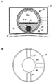
図4は前記ヘッドホン3の外観図である。図5はヘッドホン3の頂部に取り付けられている方位センサ4の構成図である。ヘッドホン3の両方の耳あて部には小型スピーカが内蔵されており、それぞれ前記アンプ18から出力された左右のアナログ楽音信号が入力される。そしてアーチの頂部には方位センサ4が設けられている。方位センサ4は円筒形のケース28に収納されており、図5(B)に示すようにコンパス20及びフォトセンサ25,26,27で構成されている。
【0042】
図5(A)に示すようにコンパス20は、球状の透明アクリルケース22内に球状磁石体21を収納し、この球状磁石体21と透明アクリルケース22の内壁面との隙間に液体23を充填したものである。この液体23は無色透明のものである。
【0043】
球状磁石体21は液体23内で重力に対して常に上下関係を維持すると共に南北の方位を指すようにするため、中央部に板状磁石21aを収納し、上部に空間21c,下部に重り21bを有している。
【0044】
図6に示すように、このコンパス20すなわちヘッドホン3がどの向きになってもどのように傾いてもこの球状磁石体21aは必ず特定の部位が地磁気により北を指し、重り21bが重力方向を向くように透明アクリルケース20内で回転揺動する。
【0045】
なお、透明アクリルケース22内で球状磁石体21は液体23で浮揚しており、摩擦なく透明アクリルケース22内で回転揺動できる。
【0046】
図7に示すように球状磁石体21の表面は、青と赤のグラデーションで彩色されている。青のグラデーションは同図(A),(B)に示すようにその濃度が方位を表すように経線状に彩色されており、北→東→南→西→北と回転するにしたがって青の濃度が薄くなるようにされている。
【0047】
すなわち、青色の濃度(薄さ)が方位角(北を0度とする時計回りの角度)を表すことになる。赤のグラデーションは同図(C),(D)に示すようにその濃度が傾斜角を示すように緯線状に彩色されており、透明アクリルケース20が下向きに傾斜するほど赤の濃度の高い部分が現れるようになっている。
【0048】
実際には、この赤グラデーションと青グラデーションが同じ球面にされており、両色が混ざり合っている。
【0049】
図5(B)に示すように、このコンパス20の側面に向けてフォトセンサ25〜27が設けられている。フォトセンサ25は青色の濃度を検出するセンサであり、フォトセンサ26,27は赤色の濃度を検出するセンサである。フォトセンサ25はヘッドホン3の前側からコンパス20の側面に向けられており、フォトセンサ26はヘッドホン3の右側からコンパス20の側面に向けられており、フォトセンサ27はヘッドホン3の後側からコンパス20の側面に向けられている。
【0050】
図8は、各フォトセンサ25,26,27の構成を示す。LED30及びフォトダイオード32がコンパス20に向けて設けられ、これらLED30,フォトダイオード32の前面に所定色のみを通過させる光学フィルタが設けられている。LED30は電池31によって連続点灯され、コンパス20の球状磁石体21の表面を照射している。また、フォトダイオード32は、上記LED30が照射した光の球状磁石体21表面の反射光を受光することによって抵抗値が変化する。
【0051】
このフォトダイオード32はアンプ33に接続されている。アンプ33はフォトダイオード32の検出値を増幅してLPF34に入力する。LPF34は、検出値のうち微小な振動成分を除去して動作としての頭の動きのみを抽出し、係数発生部5に出力する。
【0052】
フォトセンサ25が前側からコンパス20の球状磁石体21の青色濃度を検出することにより、図9(A)に示す濃度検出値と方位角の関係に基づいて、このヘッドホン3がどの方位を向いているかを検出することができる。
【0053】
また、フォトセンサ26は右側面から球状磁石体21の赤色を検出することにより、図9(B)に示す濃度検出値と傾斜角(仰角)の関係に基づいて、ヘッドホン3が右にどの程度傾いているかを検出することができる。
【0054】
さらに、フォトセンサ27は後側から球状磁石体21の赤色を検出することにより、図9(B)に示す濃度検出値と仰角の関係に基づいて、ヘッドホン3がどの程度上を向いているかを検出することができる。
【0055】
これらの検出内容を係数発生部5に入力することにより、係数発生部5は、入力装置6によって設定された仮想発音位置がヘッドホン3からみてどの方向・距離にあるかを計算することができ、この方向・距離を信号処理的に実現するためのディレイライン11のタップ位置及びCh1〜Ch8のゲイン乗算器12,13のゲインを算出して音像定位部2に出力する。
【0056】
なお、このように方位センサとして地磁気センサを用いたことにより、他のセンサ例えばジャイロセンサなどに比べて以下のような利点がある。首を傾けて回してもズレや誤差が生じないため、上体を動かして演奏する電子ピアノのヘッドホンに用いても安定した音像定位を実現することができる。地磁気が常時安定しているため、電子楽器やAV機器など音源となる装置とのキャリブレーション(位置関係の設定)を1回とれば、以後使用開始時や使用途中に取り直す必要がなく、以後装置を移動させるまでキャリブレーションをとることが不要となる。また、ジャイロなど他の方位センサに比べて安価である。
【0057】
なお、方位磁石を浮かせている液体の粘度を調節することで、頭の回転に対する応答性を調節することができる。また、この検出内容の係数発生部5への伝送は、有線でも無線でもよい。無線で行う場合には、電源として電池を用いるが、その電池は充電式電池でもよい。例えば、ヘッドホンを掛けておくホルダに充電機能を設け、そのホルダに載せている間に充電されるようにしてもよい。また、有線で行う場合には、ヘッドホンのオーディオケーブルを介して信号及び電源の送受をするようにすることもできる。
【0058】
図10,図11は上記係数発生部5の動作を示すフローチャートである。図10において、この装置の動作がスタートすると、まず、各種レジスタをイニシャライズする。正面方位レジスタ5aには0度のデータが入力される。すなわち、ヘッドホン3の正面(仮想的壁面8)は真北に向いているとされる。そして、仮想発音位置レジスタ5bにはx,y座標として0,0がセットされる。すなわち、ヘッドホン3の正面に仮想発音位置があるように設定される。こののち設定ボタン7のオン(s2)又は入力装置6の操作(s3)があるまで待機する。設定ボタン7がオンされると(s2)、そのときの方位センサ4の方位(フォトセンサ25の検出値)を読み取り(s4)、その方位を正面方位レジスタ5aに記憶する(s5)。一方、入力装置6が操作されると、その操作に応じて仮想発音位置レジスタ5bのx,y座標を書き換える(s6)。すなわち、入力装置6が左右に操作されるとその操作に応じてx座標の値を増減し、入力装置6が上下に操作されるとその操作に応じてy座標の値を増減する。
【0059】
図11はタイマインタラプト動作である。この動作は数十ミリ秒に1回の頻度で行われる定位位置制御動作である。まず、方位センサ4に内蔵されている3つのフォトセンサ25,26,27の検出値を読み取る(s11)。そして、この検出値に基づいてヘッドホン3の向き(方位)及び傾きを検出する(s12,s13)。このデータと正面方位データ,仮想音源のz0 及びx,y座標に基づいて仮想発音位置に対する方向・距離を算出する(s14)。この方向・距離に基づいて各チャンネルに与えるゲイン及びディレイライン11のタップ位置を決定し(s15)、これらを音像定位部2に送出する(s16)。
【0060】
なお、ゲインやタップ位置などの割出しは、算出された方向・距離に基づき所定の演算式を用いて算出するようにしてもよく、種々の方向・距離に対応する係数をテーブルとして記憶しておき、その中の適当なものを読み出すようにしてもよい。この係数テーブルは複数の距離・方向に対応するFIRフィルタの伝達特性パラメータを記憶したテーブルに比べてデータ量が極めて小さいためこのようにしてもメモリ容量は少なくてすむ。
【0061】
次に、本発明の第2の実施例について説明する。上述の第1の実施例では、センサ付のヘッドホンを利用し、仮想音像位置を8箇所に設定したが、このような構成では、安価なシステムを構成することは難しい。そこで、第2の実施例では、通常のヘッドホンを利用して、仮想音像位置(仮想スピーカ位置)を4箇所に設定する場合を説明する。聴取者は正面を向き、ヘッドホンの向きはほぼ一定の場合を想定する。
【0062】
図13は、第2の実施例の音像定位装置における仮想スピーカ位置と音源位置VPを表す概念図である。本実施例では、左右前方、左右後方の4箇所に、仮想スピーカSP1からSP4を配置する。音源位置VPの方向は、図に示すように頭部周囲の仮想スピーカSP1からSP4間のレベル重み付けによって決定される。また、音源位置VPと聴取者位置に対して点対称位置VP’から原音と数〜10数ms遅らせた音を発生させて定位感を強調する。この点対称位置VP’からの音は、壁面からの反射音を想定しており後述のBPFを介することにより、反射による減衰がシミュレートされる。
【0063】
音源位置VPの距離は、直接音(x)、初期反射音(y)、残響音(z)のレベル差、到着時間の遅れの大きさによって制御される。例えば、レベル差の制御は、後述の乗算部に供給されるDSPパラメータのゲイン係数によって制御され、初期反射音用のゲイン係数をaとし、残響音用のゲイン係数をbとすると、音源位置VPの距離を近くに設定する場合は、直接音のレベルが初期反射音と残響音のレベルの和よりも大きくなるようにx>ay+bzの関係が成り立つように制御し、音源位置VPの距離を遠くに設定する場合は、直接音のレベルが初期反射音と残響音のレベルの和よりも小さくなるようにx<ay+bzの関係が成り立つように制御する。
【0064】
図14は、第2の実施例による音像定位装置の基本構成を表すブロック図である。
【0065】
バス51には、検出回路52、表示回路53、RAM54、ROM55、CPU56、外部記憶装置57、通信インターフェイス58、音源回路59、タイマ60が接続される。
【0066】
ユーザは、検出回路52に接続される操作子(入力手段)62を用いて、後述の物理パラメータ、プリセットの入力及び選択等をすることができる。操作子62は、例えば、ロータリーエンコーダ、スライダ、マウス、キーボード、鍵盤、ジョイスティック、スイッチ等、ユーザの入力に応じた信号を出力できるものならどのようなものでもよい。また、複数の入力手段が接続されていてもよい。
【0067】
表示回路53は、ディスプレイ63に接続され、後述の物理パラメータ、プリセット番号等の各種情報をディスプレイ63に表示することができる。ディスプレイ63は、液晶表示装置(LCD)、発光ダイオード(LED)等で構成されるが、各種情報を表示できるものならばどのようなものでもよい。
【0068】
外部記憶装置57は、外部記憶装置用のインターフェイスを含み、そのインターフェイスを介してバス51に接続される。外部記憶装置57は、例えば、フラッシュメモリなどの半導体メモリ、フロッピディスクドライブ(FDD)、ハードディスクドライブ(HDD)、光磁気ディスク(MO)ドライブ、CD−ROM(コンパクトディスク−リードオンリィメモリ)ドライブ、DVD(Digital Versatile Disc)ドライブ等である。外部記憶装置57には、ユーザが設定するプリセット等を保存することができる。
【0069】
RAM54は、フラグ、レジスタ又はバッファ、各種データ等を記憶するCPU56用のワーキングエリアを有する。
【0070】
ROM55には、プリセットデータ、関数テーブル、各種パラメータ及び制御プログラム等を記憶することができる。この場合、プログラム等を重ねて、外部記憶装置57に記憶する必要は無い。CPU56は、ROM55又は、外部記憶装置57に記憶されている制御プログラム等に従い、演算又は制御を行う。
【0071】
タイマ60は、CPU56及バス51に接続されており、基本クロック信号、割り込み処理タイミング等をCPU56に指示する。
【0072】
音源回路59は、供給されるMIDI信号等に応じて楽音信号を生成し、外部に出力する。本実施例では、音源回路59は、波形ROM64、波形読出装置65、DSP(DIGITAL SOUNDFIELD PROCESSOR)66及びD/Aコンバータ(DAC)67で構成される。
【0073】
波形読出し装置65は、CPU56の制御により波形ROM64に記憶される音源の各種音色波形を読み出す。DSP66は、波形読出し装置65が読み出す波形に残響や定位等の効果を与える。DAC67はDSP66によって各種効果が付与された波形をデジタル形式からアナログ形式に変化して外部に出力する。なお、DSP66の機能については後述する。
【0074】
なお、音源回路59は、本実施例の波形メモリ方式に限らず、FM方式、物理モデル方式、高調波合成方式、フォルマント合成方式、VCO(VoltageControlled Oscillator)+VCF(Voltage Controlled Filter)+VCA(Voltage Controlled Amplifier)のアナログシンセサイザ方式等、どのような方式を用いたものであってもよい。
【0075】
また、音源回路59は、専用のハードウェアを用いて構成するものに限らず、DSP(Degital Signal Processor)+マイクロプログラムを用いて構成してもよいし、CPU+ソフトウェアのプログラムで構成するようにしてもよいし、サウンドカードのようなものでもよい。
【0076】
さらに、1つの音源回路を時分割で使用することにより複数の発音チャンネルを形成するようにしてもよいし、複数の音源回路を用い、1つの発音チャンネルにつき1つの音源回路で複数の発音チャンネルを構成するようにしてもよい。
【0077】
通信インターフェイス58は、他の楽器、音響機器、コンピュータ等に接続できるものであり、少なくとも電子楽器と接続できるものである。この場合、通信インターフェイス58は、MIDIインターフェイス、RS−232C、USB(ユニバーサル・シリアル・バス)、IEEE1394(アイトリプルイー1394)等の汎用のインターフェイスを用いて構成する。
【0078】
図15は、第2の実施例におけるデータフローを示す概念的ブロック図である。
【0079】
パラメータ入力部71は、例えば、図14の入力手段62及び外部記憶装置57又はROM55によって構成され、パラメータ変換部72に各種の物理パラメータを入力する。
【0080】
パラメータ入力部71では、仮想空間情報及び再生条件が入力される。これらの情報の入力は、入力手段62を介してユーザが行うか又はこれらの情報を予め含むプリセットの中からユーザが選択することにより行われる。
【0081】
仮想空間情報には、ホール、スタジオ等の空間の種類及び形状、受聴者から見た仮想音源の距離、及び方向が含まれる。再生条件には、受聴者の個人差、使用するヘッドホンの特性等が含まれる。
【0082】
入力された仮想空間情報及び再生条件は、物理パラメータとして、パラメータ変換部72に送られる。
【0083】
パラメータ変換部72は、例えば図14のCPU56で構成され、入力される物理パラメータをDSPパラメータに変換する。物理パラメータからDSPパラメータへの変換はパラメータ変換テーブル73を参照することにより行われる。パラメータ変換テーブル73は、図14の外部記憶装置57、又はROM55に保存されている。
【0084】
DSPパラメータは、後述の図16の定位制御部85で、FIRフィルタ15及びIIRフィルタ41等を制御するためのフィルタ係数、各種乗算部を制御するためのゲイン係数、ディレイ11bの遅延時間等を含み、また、残響付加部86を制御するための各種パラメータを含む。
【0085】
変換されたDSPパラメータは、音源ユニット(音源回路)59に送られる。音源ユニット59では、入力されるDSPパラメータに基づき各種効果を波形データに付与して楽音信号として出力する。
【0086】
なお、DSPパラメータは、物理パラメータから変換されるだけでなく、定位パターンや、残響パターン、又はそれらの組合せのパターンごとに、予めプリセットとして記憶されていてもよい。
【0087】
図16は、図14のDSP66の機能を示すブロック図である。DSP66は、乗算部84、定位制御部85、残響付加部86、乗算部87、加算部88、加算部90、マスターイコライザ89を有する。
【0088】
図14の波形読出し装置65に読み出された複数チャンネル(xNch)の波形データはDSP66に入力されると、それぞれ、直接音、初期反射音、残響音用の波形データとして3系統に分けられる。複数チャンネル(xNch)の直接音用の波形データはそのままDryInとして、定位制御部85に入力される。
【0089】
複数チャンネル(xNch)の初期反射音用の波形データは、乗算部84aで受聴者と仮想発音位置の設定距離により定められるゲイン係数に従い乗算された後、ERInとして、定位制御部85に入力される。複数チャンネル(xNch)の残響音用の波形データは、乗算部84bで受聴者と仮想発音位置の設定距離により定められるゲイン係数に従い乗算された後、加算部90で加算されてRevInとして、残響付加部86に入力される。
【0090】
定位制御部85は、後に図17を用いて詳述するように、仮想発音位置を制御する。
【0091】
残響付加部86は、入力される波形データに、残響を付加して、仮想音源の距離感を創出すると共に、仮想空間をシミュレートし、残響音として出力する。残響音のパターンは、空間タイプによって残響時間、直接音及び初期反射音のレベル差、周波数帯域毎の減衰量が異なる。これら、残響時間、直接音及び初期反射音とのレベル差、周波数帯域毎の減衰量は、DSPパラメータとして入力される。これらDSPパラメータは、ユーザが入力する物理パラメータを変換して生成するが、空間タイプ(ホール、スタジオなど)ごとにプリセットとして記憶しておいてもよい。
【0092】
定位制御部85及び残響付加部86から出力される波形データは、それぞれ乗算部87a、87bで乗算され、加算部88で加算合成されて1つの波形データとして、マスターイコライザ89に入力される。マスターイコライザ89では、入力される波形データの周波数特性を補正して、図14のDAC67に出力する。
【0093】
図17は、図16の定位制御部(LOC)85の機能を示すブロック図である。定位制御部85は、複数チャンネル(xNch)のそれぞれに対応する複数の前段部85aと、1つの後段部85bで構成される。複数の入力を有する事、チャンネル数が少ない事等を除き基本的な構成は図3に示す第1の実施例とほぼ同様のものであり、同様の機能を持つ構成には同様の参照番号を附す。
【0094】
前段部85aは、直接音用の波形データの入力DryInと初期反射音用の波形データの入力ERInを有している。DryInから入力された波形データは、左右前方及び左右後方の4chに分けられた後、それぞれ乗算部12で乗算され加算部14に入力される。乗算部12のゲイン係数は、DSPパラメータとして入力される。
【0095】
ERInから入力された波形データは、ディレイ11bで、DSPパラメータ中の遅延時間に基づき直接音から数〜10数ms遅れて初期反射音としてBPF40に出力される。BPF40は、初期反射音に対して、反射による減衰を模するために設けられている。その後初期反射音は、左右前方及び左右後方の4chに分けられた後、それぞれ乗算部13で乗算され加算部14に入力される。乗算部13のゲイン係数は、DSPパラメータとして入力される。
【0096】
加算部14では、直接音及び初期反射音を加算合成して後段部85bの加算部19に送る。
【0097】
FIRフィルタ15は左耳用フィルタ15L,右耳用フィルタ15Rの2系統を有している。Ch1のFIRフィルタ15Lは、楽音が図13の左前方から左耳に聞こえてくる場合の響きを頭部音響伝達関数によりシミュレートし、Ch1のFIRフィルタ15Rは、楽音が図13の左前方から右耳に聞こえてくる場合の響きを頭部音響伝達関数によりシミュレートする。同様にCh2〜Ch4のFIRフィルタ15L,FIRフィルタ15Rはそれぞれ右前方、左右後方から左右両耳への楽音の伝達を頭部音響伝達関数によりシミュレートする。
【0098】
仮想発音位置の方向がこれら基本方向の中間の方向であった場合、基本方向のうちその仮想発音位置の方向を囲む2方向となす角度を算出し、その角度に対応するディレイ11bの遅延時間及びゲイン係数をディレイ11b及び各チャンネルのゲイン乗算器12,13に与える。
【0099】
各チャンネルのFIRフィルタ15L、Rから出力された波形データはそれぞれ加算部16で加算合成される。これら加算合成されたデジタルの楽音信号(波形データ)はそれぞれ左右2チャンネルを有するIIRフィルタ41に入力される。
【0100】
IIRフィルタ41は、加算合成されたデジタルの楽音信号の特性を補正するためのフィルタであり、図3の第1の実施例のものと同様のものである。IIRフィルタ41によって補正された波形データは、図16の乗算部87aに出力される。
【0101】
以上、本発明の第2の実施例によれば、HRTF再現をインパルス応答畳み込み用FIRフィルタとその後段に配置される周波数特性補正用IIRフィルタによって実現するので、受聴者の嗜好や定位特性の差異に応じてデジタルの楽音信号を補正することができる。
【0102】
また、上記受聴者の嗜好や定位特性の差異に応じたHRTFをプリセットすることが出来るので、HRTF再現の設定を容易に行うことが出来る。
【0103】
さらに、残響音を含めた定位タイプをプリセットパターンとして記憶することが出来、ユーザはそれを選択することが出来る。
【0104】
また、以上のような構成をとることにより、FIRフィルタ及びIIRフィルタを各発音定位位置に関係なく係数固定にすることが出来、図17に示すように前段部85aを入力ライン数分備えることにより小規模な構成で多数の個別音源の定位を実現することが出来る。
【0105】
なお、本発明の実施例は、ヘッドホンを用いて受聴する場合を説明したが、図3または図17のIIRフィルタ41の後段にクロストークキャンセラを配置することにより、スピーカでの受聴にも適用できる。
【0106】
さらになお、本発明の実施例は、実施例に対応するコンピュータプログラム等をインストールした市販のコンピュータ等によって、実施させるようにしてもよい。
【0107】
その場合には、本実施例に対応するコンピュータプログラム等を、CD−ROMやフロッピーディスク等の、コンピュータが読み込むことが出来る記憶媒体に記憶させた状態で、ユーザに提供してもよい。
【0108】
その汎用コンピュータ又はコンピュータ等が、LAN、インターネット、電話回線等の通信ネットワークに接続されている場合には、通信ネットワークを介して、コンピュータプログラムや各種データ等を汎用コンピュータ又はコンピュータ等に提供してもよい。
【0109】
さらに、実施例は、1つの装置で実施するだけに限らず、さまざまな装置をMIDIや各種ネットワーク等の通信手段を用いて接続したものであってもよい。また、音源装置や自動演奏装置等を内蔵した電子楽器などで実施例を実施することもできる。ここでいう電子楽器とは、鍵盤楽器タイプ、弦楽器タイプ、管楽器タイプ、打楽器タイプ等の電子楽器である。
【0110】
以上実施例に沿って本発明を説明したが、本発明はこれらに制限されるものではない。例えば、種々の変更、改良、組合せ等が可能なことは当業者に自明であろう。
【0111】
【発明の効果】
以上のように本発明によれば、ヘッドホンによる受聴において十分な臨場感を得ることが出来る。
【0112】
また、楽器配置、受聴空間に応じた効果を選択調整することが出来る。またそれを記憶することも出来る。
【0113】
さらに、受聴者、ヘッドホンの種類毎に定位感の調整をすることが出来る。またそれを記憶することも出来る。
【図面の簡単な説明】
【図1】この発明の第1の実施例による音像定位装置のブロック図である。
【図2】同音像定位装置の音像定位方式を説明する図である。
【図3】同音像定位装置の音像定位部のブロック図である。
【図4】同音像定位装置のヘッドホンの外観図である。
【図5】同ヘッドホンに設けられる方位センサの構成図である。
【図6】同方位センサが傾斜したときの状態を示す図である。
【図7】同方位センサの球状磁石体の塗装を説明する図である。
【図8】同方位センサに設けられるフォトセンサの構成図である。
【図9】同方位センサのフォトセンサの濃度検出値と方位角、傾斜(仰角)との関係を示す図である。
【図10】同音像定位装置の係数発生部の動作を示すフローチャートである。
【図11】同音像定位装置の係数発生部の動作を示すフローチャートである。
【図12】IIRフィルタを用いた場合の周波数特性の変化を表すグラフである。
【図13】第2の実施例の音像定位装置における仮想スピーカ位置と音源位置VPを表す概念図である。
【図14】第2の実施例による音像定位装置の基本構成を表すブロック図である。
【図15】第2の実施例におけるデータフローを示す概念的ブロック図である。
【図16】図14のDSP66の機能を表すブロック図である。
【図17】図16の定位制御部(LOC)85の構成を表すブロック図である。
【符号の説明】
2…音像定位部、3…ヘッドホン、4…方位センサ、5…係数発生部、5a…正面方位レジスタ、5b…仮想発音位置レジスタ、6…入力装置、7…設定ボタン、11…ディレイライン、12,13…ゲイン乗算器、15L,15R…FIRフィルタ、16L,16R…加算器、20…コンパス、21…球状磁石体、21a…板状磁石、21b…重り、21c…空間、23…液体、25,26,27…フォトセンサ、28…ケース、30…LED、32…フォトダイオード、35…フィルタ 、40…BPF、41…IIRフィルタ、51…バス、52…検出回路、53…表示回路、54…RAM、55…ROM、56…CPU、57…外部記憶装置、58…通信インターフェイス、59…音源回路、60…タイマ、62…入力手段、63…ディスプレイ、64…波形ROM、65…波形読出装置、66…DSP、67…DAC、71…パラメータ入力部、72…パラメータ変換部、73…パラメータテーブル、84、87…乗算部、85…定位制御部、86…残響付加部、88…加算部、89…マスターイコライザ[0001]
BACKGROUND OF THE INVENTION
The present invention relates to a sound image localization apparatus that localizes a sound image of a musical sound output from an electronic musical instrument or audio equipment at a predetermined position.
[0002]
[Prior art]
Electronic musical instruments and audio equipment increase the realistic sensation of the output musical sound, so that the volume and output timing of multiple (left and right) speakers can be adjusted so that the listener can imagine that the musical sound is sounding from a certain point in space. I have control. A “certain point” of this space is referred to as a virtual sound generation position, and a virtual space region (a location where a virtual musical instrument is located) that is imaged as if a musical sound is being generated is referred to as a sound image.
[0003]
In general stereo headphones, a musical sound is supplied to left and right speakers at a predetermined balance volume, so that the sound image of the musical sound is localized.
[0004]
Since the headphones are attached to the listener's head, when the listener moves his / her head, the speaker of the headphones also follows this, and the sound image moves together with the above control alone. In order to cope with this, a headphone system has been proposed in which the position of the sound image does not change even if the head is moved by detecting that the listener has moved the head and controlling the musical sound characteristics output to the left and right speakers. (JP-A-4-44500, etc.).
[0005]
A sound image localization apparatus using an FIR filter has also been proposed (Japanese Patent Laid-Open No. 10-23600).
[0006]
[Problems to be solved by the invention]
In the headphone system, the left ear filter and the right ear filter are provided, and the response characteristic parameter corresponding to the direction of the headphone is read out and set in the filter according to the direction of the headphone. It was necessary to store parameters corresponding to many virtual pronunciation positions in the memory. For this reason, if a large parameter memory is not provided, the sound image cannot be localized accurately, and there is a disadvantage that the parameter must be read again each time the listener moves his / her head.
[0007]
Further, in the sound image localization apparatus, it is difficult to obtain an optimum localization for an unspecified listener, and the difference in effect due to the type and characteristics of headphones is large. Furthermore, sound image localization and reverberation could not be controlled systematically.
[0008]
An object of the present invention is to provide a sound image localization apparatus that can selectively adjust effects according to musical instrument arrangement and listening space.
[0009]
Furthermore, an object of the present invention is to provide a sound image localization apparatus that can adjust the localization feeling for each type of listener and headphones.
[0010]
[Means for Solving the Problems]
According to one aspect of the present invention, a sound image localization device includes a musical sound signal input unit that inputs a musical sound signal, a virtual sounding position input unit that inputs a virtual sounding position of the music signal, and a virtual sounding position of the music signal. Coefficient generating means for generating a coefficient based on the virtual sounding position and a coefficient based on the initial reflected sound position that is point-symmetric with respect to the listener position, and delaying the musical sound signal by the coefficient based on the virtual sounding position Generating means for generating a preceding sound signal and a subsequent sound signal obtained by delaying the musical sound signal by a value that is not recognized as another sound with respect to the preceding sound signal by a coefficient based on the initial reflected sound position; Performs gain adjustment on the preceding sound signal using a coefficient based on the virtual sounding position, and convolutionally calculates the sound transmission characteristics from multiple directions to both ears and the gain-adjusted preceding sound signal and outputs the result A preceding sound processing means, and performing gain adjustment on the following sound signal by a coefficient based on the initial reflected sound position, convolutionally calculating and outputting the musical sound transfer characteristic and the following sound signal adjusted in gain. A subsequent sound processing means; and an adding means for adding and outputting the signal output from the preceding sound processing means and the signal output from the subsequent sound processing means.
[0011]
DETAILED DESCRIPTION OF THE INVENTION
FIG. 1 is a diagram showing the configuration of a headphone system according to a first embodiment of the present invention. This headphone system supplies a musical sound signal generated by an electronic
[0012]
FIG. 2 is a diagram for explaining the sound image localization method of the headphone system of the first embodiment. FIG. 3 is a diagram showing a configuration of the sound
[0013]
The eight channels Ch1 to Ch8 correspond to the directions (1) to (8) in FIG. That is, the
[0014]
Similarly, the FIR filters Ch2 to Ch8 are FIR filters that perform a convolution calculation of a musical sound signal with a musical sound transmission characteristic from the directions (2) to (8) in FIG. Thus, (1) to (8) in FIG. 2 (A) indicate the front of the listener, that is, the direction with respect to the
[0015]
On the other hand, the input device 6 is an operator for setting the virtual sound generation position of the musical sound generated by the electronic
[0016]
When the input device 6 is operated to the right, the x coordinate of the virtual sound generation position is increased, and when the input device 6 is operated to the left, the x coordinate of the virtual sound generation position is decreased. Further, when the input device 6 is operated upward, the y coordinate of the virtual sound generation position is increased, and when the input device 6 is operated downward, the y coordinate of the virtual sound generation position is decreased.
[0017]
In FIG. 2A, assuming that the virtual sound generation position of the musical sound is set at a point 9 on the
[0018]
When the direction of the
[0019]
In FIG. 2A, when the virtual sound generation position 9 is moved by operating the input device 6, new angles α1, α2, α5, α6 are calculated and the localization is moved accordingly. .
[0020]
In this description, only the case where the virtual sound generation position is in the vicinity of the front of the
[0021]
Further, when the virtual sound generation position is on the rear side of the
[0022]
In this embodiment, the virtual sound generation position 9 can be set only on the
[0023]
The input device 6 at the virtual sound generation position 9 is not limited to a joystick. In addition to an operator that relatively increases or decreases coordinate values similar to the joystick, an operator that directly inputs coordinate values such as a numeric keypad, a rotary encoder In addition, a slider or the like can be used, and the virtual sound generation position may be set graphically in the image of the wall or space displayed on the monitor. Further, the setting switch 7 for setting the direction toward the
[0024]
The configuration of the sound
[0025]
The musical tone signal input from the electronic
[0026]
The
[0027]
The tap position is determined by the tap position coefficient input from the
[0028]
The preceding sound is input to the Ch1 to Ch8 gain
[0029]
The
[0030]
For example, if the tap interval is shortened to reduce the difference between the preceding sound and the following sound, the sense of distance can be reduced, and the sound image can be localized closer, and conversely, if the difference between the preceding sound and the following sound is increased, the distance feeling is increased. Becomes larger and the sound image can be localized far away. However, the difference between the preceding sound and the following sound should not exceed 20 ms. This is because if the deviation exceeds 20 ms, the listener recognizes it as another sound.
[0031]
Further, when the level difference between the preceding sound and the following sound (the difference between the gain of the
[0032]
The gains of the Ch1 to Ch8 gain
[0033]
The
[0034]
When the direction of the virtual sound generation position is an intermediate direction between these basic directions (1) to (8), the
[0035]
The signals output from the FIR filters 15L of the respective channels are added and synthesized by the
[0036]
The
[0037]
Although there are individual differences in HRTF, by using the
[0038]
FIG. 12 is a diagram illustrating changes in frequency characteristics when the
[0039]
In the example of FIG. 12, the high frequency and low frequency are boosted, but the
[0040]
The tone signal corrected by the
[0041]
FIG. 4 is an external view of the
[0042]
As shown in FIG. 5A, the
[0043]
The
[0044]
As shown in FIG. 6, the
[0045]
Note that the
[0046]
As shown in FIG. 7, the surface of the
[0047]
That is, the density (thinness) of blue represents the azimuth angle (clockwise angle with north being 0 degree). The red gradation is colored like a parallel line so that the density indicates an inclination angle as shown in FIGS. 2C and 2D, and the portion where the density of red is higher as the transparent
[0048]
Actually, this red gradation and blue gradation are made the same spherical surface, and both colors are mixed.
[0049]
As shown in FIG. 5B,
[0050]
FIG. 8 shows the configuration of each photosensor 25, 26, 27. An
[0051]
This
[0052]
When the
[0053]
Further, the
[0054]
Further, the
[0055]
By inputting these detection contents to the
[0056]
The use of the geomagnetic sensor as the azimuth sensor has the following advantages over other sensors such as a gyro sensor. Even if the head is tilted and rotated, no deviation or error occurs, so that stable sound image localization can be realized even when used for headphones of an electronic piano that is played by moving the upper body. Since geomagnetism is always stable, once calibration (positional setting) with a device that is a sound source such as an electronic musical instrument or AV equipment is performed once, there is no need to re-read at the beginning of use or during use. It is not necessary to take calibration until it is moved. Moreover, it is cheaper than other azimuth sensors such as gyros.
[0057]
In addition, the responsiveness with respect to the rotation of the head can be adjusted by adjusting the viscosity of the liquid floating the compass. Further, the transmission of the detection contents to the
[0058]
10 and 11 are flowcharts showing the operation of the
[0059]
FIG. 11 shows a timer interrupt operation. This operation is a localization position control operation performed once every several tens of milliseconds. First, the detection values of the three
[0060]
Note that the index of gain, tap position, etc. may be calculated using a predetermined arithmetic expression based on the calculated direction / distance, and coefficients corresponding to various directions / distances are stored as a table. Alternatively, an appropriate one of them may be read out. Since this coefficient table has an extremely small data amount compared to a table storing transfer characteristic parameters of FIR filters corresponding to a plurality of distances and directions, the memory capacity can be reduced even in this way.
[0061]
Next, a second embodiment of the present invention will be described. In the first embodiment described above, the headphone with sensor is used and the virtual sound image positions are set at eight places. However, with such a configuration, it is difficult to configure an inexpensive system. Thus, in the second embodiment, a case where virtual sound image positions (virtual speaker positions) are set at four locations using normal headphones will be described. It is assumed that the listener faces the front and the headphone direction is almost constant.
[0062]
FIG. 13 is a conceptual diagram showing a virtual speaker position and a sound source position VP in the sound image localization apparatus of the second embodiment. In the present embodiment, the virtual speakers SP1 to SP4 are arranged at four places, left and right front and left and right rear. The direction of the sound source position VP is determined by level weighting between the virtual speakers SP1 to SP4 around the head as shown in the figure. Further, the sense of localization is emphasized by generating a sound delayed from the original sound by several to several tens of ms from the point symmetrical position VP ′ with respect to the sound source position VP and the listener position. The sound from this point symmetry position VP ′ is assumed to be reflected from the wall surface, and attenuation due to reflection is simulated through a BPF described later.
[0063]
The distance of the sound source position VP is controlled by the level difference between the direct sound (x), the early reflection sound (y), the reverberation sound (z), and the delay time of arrival time. For example, the control of the level difference is controlled by a gain coefficient of a DSP parameter supplied to a later-described multiplication unit, where a is a gain coefficient for initial reflection sound and b is a gain coefficient for reverberation sound. When the distance is set close, the control is performed so that the relationship of x> ay + bz is established so that the level of the direct sound is larger than the sum of the levels of the initial reflected sound and the reverberation sound, and the distance of the sound source position VP is increased. Is set so that the relationship of x <ay + bz is established so that the level of the direct sound is smaller than the sum of the levels of the initial reflected sound and the reverberant sound.
[0064]
FIG. 14 is a block diagram showing the basic configuration of a sound image localization apparatus according to the second embodiment.
[0065]
A
[0066]
The user can input and select physical parameters and presets described later by using an operator (input means) 62 connected to the
[0067]
The
[0068]
The
[0069]
The
[0070]
The
[0071]
The
[0072]
The
[0073]
The
[0074]
The
[0075]
The
[0076]
Further, a plurality of tone generation channels may be formed by using one tone generator circuit in a time-sharing manner, or a plurality of tone generation circuits may be formed by using one tone generator circuit for each tone generation channel. You may make it comprise.
[0077]
The
[0078]
FIG. 15 is a conceptual block diagram showing a data flow in the second embodiment.
[0079]
The
[0080]
In the
[0081]
The virtual space information includes the type and shape of a space such as a hall or studio, the distance and direction of the virtual sound source viewed from the listener. The reproduction conditions include individual differences among listeners, characteristics of headphones to be used, and the like.
[0082]
The input virtual space information and reproduction conditions are sent to the
[0083]
The
[0084]
The DSP parameters include a filter coefficient for controlling the
[0085]
The converted DSP parameter is sent to a sound source unit (sound source circuit) 59. The
[0086]
The DSP parameter is not only converted from the physical parameter, but may be stored in advance as a preset for each of the localization pattern, the reverberation pattern, or a combination thereof.
[0087]
FIG. 16 is a block diagram showing functions of the
[0088]
When the waveform data of a plurality of channels (xNch) read by the
[0089]
The waveform data for the initial reflected sound of a plurality of channels (xNch) is multiplied by the
[0090]
The
[0091]
The
[0092]
The waveform data output from the
[0093]
FIG. 17 is a block diagram illustrating functions of the localization control unit (LOC) 85 of FIG. The
[0094]
The
[0095]
The waveform data input from the ERIn is output to the
[0096]
The adding
[0097]
The
[0098]
When the direction of the virtual sounding position is an intermediate direction between these basic directions, an angle formed with two directions surrounding the direction of the virtual sounding position in the basic direction is calculated, and the delay time of the
[0099]
The waveform data output from the FIR filters 15L and R of each channel is added and synthesized by the
[0100]
The
[0101]
As described above, according to the second embodiment of the present invention, since the HRTF reproduction is realized by the impulse response convolution FIR filter and the frequency characteristic correcting IIR filter arranged at the subsequent stage, the difference in the listener's preference and localization characteristics. The digital musical tone signal can be corrected according to the above.
[0102]
In addition, since HRTFs can be preset according to the listener's preference and localization characteristics, HRTF reproduction can be easily set.
[0103]
Furthermore, a localization type including a reverberation sound can be stored as a preset pattern, and the user can select it.
[0104]
Further, by adopting the above-described configuration, the FIR filter and the IIR filter can be fixed regardless of the sound localization position, and as shown in FIG. 17, the preceding
[0105]
Although the embodiment of the present invention has been described with respect to listening using headphones, it can also be applied to listening through a speaker by arranging a crosstalk canceller after the
[0106]
Furthermore, the embodiments of the present invention may be implemented by a commercially available computer in which a computer program or the like corresponding to the embodiment is installed.
[0107]
In that case, the computer program or the like corresponding to the present embodiment may be provided to the user while being stored in a storage medium that can be read by the computer, such as a CD-ROM or a floppy disk.
[0108]
When the general-purpose computer or computer is connected to a communication network such as a LAN, the Internet, or a telephone line, the computer program and various data may be provided to the general-purpose computer or the computer via the communication network. Good.
[0109]
Furthermore, the embodiment is not limited to being implemented by a single device, and various devices may be connected using communication means such as MIDI or various networks. In addition, the embodiment can be implemented with an electronic musical instrument or the like incorporating a sound source device or an automatic performance device. The electronic musical instrument here is an electronic musical instrument such as a keyboard musical instrument type, a stringed musical instrument type, a wind instrument type, or a percussion instrument type.
[0110]
Although the present invention has been described with reference to the embodiments, the present invention is not limited thereto. It will be apparent to those skilled in the art that various modifications, improvements, combinations, and the like can be made.
[0111]
【The invention's effect】
As described above, according to the present invention, it is possible to obtain a sufficient sense of reality in listening with headphones.
[0112]
In addition, it is possible to select and adjust the effect according to the instrument arrangement and listening space. You can also remember it.
[0113]
Furthermore, the sense of localization can be adjusted for each type of listener and headphones. You can also remember it.
[Brief description of the drawings]
FIG. 1 is a block diagram of a sound image localization apparatus according to a first embodiment of the present invention.
FIG. 2 is a diagram for explaining a sound image localization method of the sound image localization apparatus.
FIG. 3 is a block diagram of a sound image localization unit of the sound image localization apparatus.
FIG. 4 is an external view of headphones of the sound image localization apparatus.
FIG. 5 is a configuration diagram of an orientation sensor provided in the headphone.
FIG. 6 is a diagram showing a state when the same-direction sensor is tilted.
FIG. 7 is a view for explaining painting of a spherical magnet body of the same direction sensor.
FIG. 8 is a configuration diagram of a photosensor provided in the same direction sensor.
FIG. 9 is a diagram illustrating a relationship between a density detection value of a photosensor of the same azimuth sensor, an azimuth angle, and an inclination (elevation angle).
FIG. 10 is a flowchart showing an operation of a coefficient generation unit of the sound image localization apparatus.
FIG. 11 is a flowchart showing an operation of a coefficient generation unit of the sound image localization apparatus.
FIG. 12 is a graph showing changes in frequency characteristics when an IIR filter is used.
FIG. 13 is a conceptual diagram showing a virtual speaker position and a sound source position VP in the sound image localization apparatus of the second embodiment.
FIG. 14 is a block diagram showing a basic configuration of a sound image localization apparatus according to a second embodiment.
FIG. 15 is a conceptual block diagram showing a data flow in the second embodiment.
16 is a block diagram showing functions of the
17 is a block diagram showing a configuration of a localization control unit (LOC) 85 in FIG.
[Explanation of symbols]
DESCRIPTION OF
Claims (5)
前記楽音信号の仮想発音位置を入力する仮想発音位置入力手段と、
前記楽音信号の仮想発音位置に基づく係数と、前記仮想発音位置と聴取者位置に対して点対称位置である初期反射音位置に基づく係数とを発生する係数発生手段と、
前記仮想発音位置に基づく係数により前記楽音信号をディレイさせた先行音信号と、前記初期反射音位置に基づく係数により前記先行音信号に対して別の音と認識されない値で前記楽音信号をディレイさせた後行音信号とを生成する生成手段と、
前記先行音信号に対し前記仮想発音位置に基づく係数によるゲイン調整を行い、複数の方向から両耳への楽音伝達特性と該ゲイン調整された先行音信号とを畳み込み演算して出力する先行音処理手段と、
前記後行音信号に対し前記初期反射音位置に基づく係数によるゲイン調整を行い、前記楽音伝達特性と該ゲイン調整された後行音信号とを畳み込み演算して出力する後行音処理手段と、
前記先行音処理手段から出力される信号と前記後行音処理手段から出力される信号とを加算して出力する加算手段と
を有する音像定位装置。A music signal input means for inputting a music signal;
Virtual sound generation position input means for inputting a virtual sound generation position of the musical sound signal;
Coefficient generating means for generating a coefficient based on a virtual sounding position of the musical sound signal and a coefficient based on an initial reflected sound position that is a point-symmetrical position with respect to the virtual sounding position and a listener position;
The musical sound signal is delayed by a value that is not recognized as another sound with respect to the preceding sound signal by the coefficient based on the initial reflected sound position and the preceding sound signal that is delayed by the coefficient based on the virtual sounding position. Generating means for generating a subsequent sound signal;
Prior sound processing for performing gain adjustment on the preceding sound signal by a coefficient based on the virtual sound generation position, and convolutionally calculating and outputting the musical sound transmission characteristics from a plurality of directions to both ears and the gain-adjusted preceding sound signal Means,
A subsequent sound processing means for performing gain adjustment by a coefficient based on the initial reflected sound position with respect to the subsequent sound signal, convolutionally calculating the musical sound transfer characteristic and the gain-adjusted subsequent sound signal, and outputting the result;
A sound image localization apparatus comprising: an adding unit that adds and outputs a signal output from the preceding sound processing unit and a signal output from the subsequent sound processing unit.
前記楽音信号の仮想発音位置を入力する仮想発音位置入力工程と、
前記楽音信号の仮想発音位置に基づく係数と、前記仮想発音位置と聴取者位置に対して点対称位置である初期反射音位置に基づく係数とを発生する係数発生工程と、
前記仮想発音位置に基づく係数により前記楽音信号をディレイさせた先行音信号と、前記初期反射音位置に基づく係数により前記先行音信号に対して別の音と認識されない値で前記楽音信号をディレイさせた後行音信号とを生成する生成工程と、
前記先行音信号に対し前記仮想発音位置に基づく係数によるゲイン調整を行い、複数の方向から両耳への楽音伝達特性と該ゲイン調整された先行音信号とを畳み込み演算して出力する先行音処理工程と、
前記後行音信号に対し前記初期反射音位置に基づく係数によるゲイン調整を行い、前記楽音伝達特性と該ゲイン調整された後行音信号とを畳み込み演算して出力する後行音処理工程と、
前記先行音処理工程で出力される信号と前記後行音処理工程で出力される信号とを加算して出力する加算工程と
を有する音像定位方法。A music signal input process for inputting a music signal;
A virtual sound generation position input step of inputting a virtual sound generation position of the musical sound signal;
A coefficient generating step for generating a coefficient based on a virtual sounding position of the musical sound signal and a coefficient based on an initial reflected sound position that is a point-symmetrical position with respect to the virtual sounding position and a listener position;
The musical sound signal is delayed by a value that is not recognized as another sound with respect to the preceding sound signal by the coefficient based on the initial reflected sound position and the preceding sound signal that is delayed by the coefficient based on the virtual sounding position. Generating a subsequent sound signal;
Prior sound processing for performing gain adjustment on the preceding sound signal by a coefficient based on the virtual sound generation position, and convolutionally calculating and outputting the musical sound transmission characteristics from a plurality of directions to both ears and the gain-adjusted preceding sound signal Process,
A subsequent sound processing step of performing gain adjustment by a coefficient based on the initial reflected sound position with respect to the subsequent sound signal, and convolutionally calculating and outputting the musical sound transfer characteristic and the subsequent sound signal adjusted in gain;
A sound image localization method comprising: an adding step of adding and outputting the signal output in the preceding sound processing step and the signal output in the subsequent sound processing step.
前記楽音信号の仮想発音位置を入力する仮想発音位置入力手順と、
前記楽音信号の仮想発音位置に基づく係数と、前記仮想発音位置と聴取者位置に対して点対称位置である初期反射音位置に基づく係数とを発生する係数発生手順と、
前記仮想発音位置に基づく係数により前記楽音信号をディレイさせた先行音信号と、前記初期反射音位置に基づく係数により前記先行音信号に対して別の音と認識されない値で前記楽音信号をディレイさせた後行音信号とを生成する生成手順と、
前記先行音信号に対し前記仮想発音位置に基づく係数によるゲイン調整を行い、複数の方向から両耳への楽音伝達特性と該ゲイン調整された先行音信号とを畳み込み演算して出力する先行音処理手順と、
前記後行音信号に対し前記初期反射音位置に基づく係数によるゲイン調整を行い、前記楽音伝達特性と該ゲイン調整された後行音信号とを畳み込み演算して出力する後行音処理手順と、
前記先行音処理手順で出力される信号と前記後行音処理手順で出力される信号とを加算して出力する加算手順と
を有する音像定位手順をコンピュータに実行させるためのプログラムを記録した媒体。Music signal input procedure for inputting music signal,
A virtual sounding position input procedure for inputting a virtual sounding position of the musical sound signal;
A coefficient generation procedure for generating a coefficient based on a virtual sound generation position of the musical sound signal and a coefficient based on an initial reflected sound position that is a point-symmetrical position with respect to the virtual sound generation position and a listener position;
The musical sound signal is delayed by a value that is not recognized as another sound with respect to the preceding sound signal by the coefficient based on the initial reflected sound position and the preceding sound signal that is delayed by the coefficient based on the virtual sounding position. A generation procedure for generating a subsequent sound signal;
Prior sound processing for performing gain adjustment on the preceding sound signal by a coefficient based on the virtual sound generation position, and convolutionally calculating and outputting the musical sound transmission characteristics from a plurality of directions to both ears and the gain-adjusted preceding sound signal Procedure and
A subsequent sound processing procedure for performing gain adjustment by a coefficient based on the initial reflected sound position with respect to the subsequent sound signal, and convolutionally calculating and outputting the musical sound transfer characteristic and the subsequent sound signal adjusted in gain.
A medium on which is recorded a program for causing a computer to execute a sound image localization procedure including an addition procedure for adding and outputting a signal output in the preceding sound processing procedure and a signal output in the subsequent sound processing procedure.
Priority Applications (3)
| Application Number | Priority Date | Filing Date | Title |
|---|---|---|---|
| JP2000220876A JP3624805B2 (en) | 2000-07-21 | 2000-07-21 | Sound image localization device |
| US09/908,906 US20020164037A1 (en) | 2000-07-21 | 2001-07-19 | Sound image localization apparatus and method |
| GB0117793A GB2370480B (en) | 2000-07-21 | 2001-07-20 | Sound image localization apparatus and method |
Applications Claiming Priority (1)
| Application Number | Priority Date | Filing Date | Title |
|---|---|---|---|
| JP2000220876A JP3624805B2 (en) | 2000-07-21 | 2000-07-21 | Sound image localization device |
Related Child Applications (1)
| Application Number | Title | Priority Date | Filing Date |
|---|---|---|---|
| JP2004258918A Division JP2005051801A (en) | 2004-09-06 | 2004-09-06 | Sound image localization apparatus |
Publications (2)
| Publication Number | Publication Date |
|---|---|
| JP2002044796A JP2002044796A (en) | 2002-02-08 |
| JP3624805B2 true JP3624805B2 (en) | 2005-03-02 |
Family
ID=18715403
Family Applications (1)
| Application Number | Title | Priority Date | Filing Date |
|---|---|---|---|
| JP2000220876A Expired - Fee Related JP3624805B2 (en) | 2000-07-21 | 2000-07-21 | Sound image localization device |
Country Status (3)
| Country | Link |
|---|---|
| US (1) | US20020164037A1 (en) |
| JP (1) | JP3624805B2 (en) |
| GB (1) | GB2370480B (en) |
Families Citing this family (18)
| Publication number | Priority date | Publication date | Assignee | Title |
|---|---|---|---|---|
| WO2005069272A1 (en) * | 2003-12-15 | 2005-07-28 | France Telecom | Method for synthesizing acoustic spatialization |
| JP4198045B2 (en) * | 2003-12-25 | 2008-12-17 | オリンパス株式会社 | In-subject position detection system |
| JP2006074572A (en) * | 2004-09-03 | 2006-03-16 | Matsushita Electric Ind Co Ltd | Information terminal |
| KR100584606B1 (en) | 2004-09-13 | 2006-05-30 | 삼성전자주식회사 | Apparatus and method for compensating frequency characteristic of earphone |
| US8880205B2 (en) * | 2004-12-30 | 2014-11-04 | Mondo Systems, Inc. | Integrated multimedia signal processing system using centralized processing of signals |
| US8015590B2 (en) | 2004-12-30 | 2011-09-06 | Mondo Systems, Inc. | Integrated multimedia signal processing system using centralized processing of signals |
| US7653447B2 (en) | 2004-12-30 | 2010-01-26 | Mondo Systems, Inc. | Integrated audio video signal processing system using centralized processing of signals |
| US8885834B2 (en) * | 2008-03-07 | 2014-11-11 | Sennheiser Electronic Gmbh & Co. Kg | Methods and devices for reproducing surround audio signals |
| JP4735993B2 (en) * | 2008-08-26 | 2011-07-27 | ソニー株式会社 | Audio processing apparatus, sound image localization position adjusting method, video processing apparatus, and video processing method |
| KR20120053587A (en) * | 2010-11-18 | 2012-05-29 | 삼성전자주식회사 | Display apparatus and sound control method of the same |
| US9736609B2 (en) | 2013-02-07 | 2017-08-15 | Qualcomm Incorporated | Determining renderers for spherical harmonic coefficients |
| EP2830327A1 (en) * | 2013-07-22 | 2015-01-28 | Fraunhofer-Gesellschaft zur Förderung der angewandten Forschung e.V. | Audio processor for orientation-dependent processing |
| CN105307086A (en) * | 2015-11-18 | 2016-02-03 | 王宋伟 | Method and system for simulating surround sound for two-channel headset |
| CN105578355B (en) * | 2015-12-23 | 2019-02-26 | 惠州Tcl移动通信有限公司 | A kind of method and system enhancing virtual reality glasses audio |
| US10440462B1 (en) * | 2018-03-27 | 2019-10-08 | Cheng Uei Precision Industry Co., Ltd. | Earphone assembly and sound channel control method applied therein |
| KR20200133632A (en) | 2019-05-20 | 2020-11-30 | 삼성전자주식회사 | directional acoustic sensor and method of detecting distance from sound source using the directional acoustic sensor |
| JP7342451B2 (en) * | 2019-06-27 | 2023-09-12 | ヤマハ株式会社 | Audio processing device and audio processing method |
| US10735885B1 (en) * | 2019-10-11 | 2020-08-04 | Bose Corporation | Managing image audio sources in a virtual acoustic environment |
Family Cites Families (10)
| Publication number | Priority date | Publication date | Assignee | Title |
|---|---|---|---|---|
| US4817149A (en) * | 1987-01-22 | 1989-03-28 | American Natural Sound Company | Three-dimensional auditory display apparatus and method utilizing enhanced bionic emulation of human binaural sound localization |
| US5440639A (en) * | 1992-10-14 | 1995-08-08 | Yamaha Corporation | Sound localization control apparatus |
| US5583936A (en) * | 1993-05-17 | 1996-12-10 | Macrovision Corporation | Video copy protection process enhancement to introduce horizontal and vertical picture distortions |
| JP3578783B2 (en) * | 1993-09-24 | 2004-10-20 | ヤマハ株式会社 | Sound image localization device for electronic musical instruments |
| DE69637736D1 (en) * | 1995-09-08 | 2008-12-18 | Fujitsu Ltd | Three-dimensional acoustic processor with application of linear predictive coefficients |
| US6091894A (en) * | 1995-12-15 | 2000-07-18 | Kabushiki Kaisha Kawai Gakki Seisakusho | Virtual sound source positioning apparatus |
| JP3750198B2 (en) * | 1996-07-01 | 2006-03-01 | ヤマハ株式会社 | Sound image localization device |
| AUPO099696A0 (en) * | 1996-07-12 | 1996-08-08 | Lake Dsp Pty Limited | Methods and apparatus for processing spatialised audio |
| TW379512B (en) * | 1997-06-30 | 2000-01-11 | Matsushita Electric Ind Co Ltd | Apparatus for localization of a sound image |
| DE69924896T2 (en) * | 1998-01-23 | 2005-09-29 | Onkyo Corp., Neyagawa | Apparatus and method for sound image localization |
-
2000
- 2000-07-21 JP JP2000220876A patent/JP3624805B2/en not_active Expired - Fee Related
-
2001
- 2001-07-19 US US09/908,906 patent/US20020164037A1/en not_active Abandoned
- 2001-07-20 GB GB0117793A patent/GB2370480B/en not_active Expired - Fee Related
Also Published As
| Publication number | Publication date |
|---|---|
| US20020164037A1 (en) | 2002-11-07 |
| GB2370480A (en) | 2002-06-26 |
| JP2002044796A (en) | 2002-02-08 |
| GB0117793D0 (en) | 2001-09-12 |
| GB2370480B (en) | 2002-12-11 |
Similar Documents
| Publication | Publication Date | Title |
|---|---|---|
| JP3624805B2 (en) | Sound image localization device | |
| US5440639A (en) | Sound localization control apparatus | |
| JP4477081B2 (en) | Using filter effects in stereo headphone devices to enhance the spatial spread of the sound source around the listener | |
| JP4295798B2 (en) | Mixing apparatus, method, and program | |
| CN112037738B (en) | Music data processing method and device and computer storage medium | |
| KR20050089085A (en) | Audio reproduction apparatus, feedback system and method | |
| JPS61257099A (en) | Acoustic control device | |
| JP3823847B2 (en) | SOUND CONTROL DEVICE, SOUND CONTROL METHOD, PROGRAM, AND RECORDING MEDIUM | |
| JP2006506884A (en) | Data presentation apparatus and method based on audio | |
| JPH10304498A (en) | Stereophonic extension device and sound field extension device | |
| JPH06315200A (en) | Distance sensation control method for sound image localization processing | |
| JP2671329B2 (en) | Audio player | |
| JP4196509B2 (en) | Sound field creation device | |
| JP2886402B2 (en) | Stereo signal generator | |
| JP3750198B2 (en) | Sound image localization device | |
| JP2005051801A (en) | Sound image localization apparatus | |
| JP2002084599A (en) | Method and system for reproducing sound | |
| JPH06285258A (en) | Video game machine | |
| JPH0415693A (en) | Sound source information controller | |
| JP3271532B2 (en) | Sound localization device for electric stringed instruments | |
| JP4426159B2 (en) | Mixing equipment | |
| JPH09182200A (en) | Device and method for controlling sound image | |
| JPH0444500A (en) | Headphone system | |
| TW201914315A (en) | Wearable audio processing device and audio processing method thereof | |
| JPH0715280Y2 (en) | Sound control device |
Legal Events
| Date | Code | Title | Description |
|---|---|---|---|
| A131 | Notification of reasons for refusal |
Free format text: JAPANESE INTERMEDIATE CODE: A131 Effective date: 20040302 |
|
| A521 | Written amendment |
Free format text: JAPANESE INTERMEDIATE CODE: A523 Effective date: 20040428 |
|
| A02 | Decision of refusal |
Free format text: JAPANESE INTERMEDIATE CODE: A02 Effective date: 20040706 |
|
| A521 | Written amendment |
Free format text: JAPANESE INTERMEDIATE CODE: A523 Effective date: 20040906 |
|
| A911 | Transfer to examiner for re-examination before appeal (zenchi) |
Free format text: JAPANESE INTERMEDIATE CODE: A911 Effective date: 20040930 |
|
| TRDD | Decision of grant or rejection written | ||
| A01 | Written decision to grant a patent or to grant a registration (utility model) |
Free format text: JAPANESE INTERMEDIATE CODE: A01 Effective date: 20041109 |
|
| A61 | First payment of annual fees (during grant procedure) |
Free format text: JAPANESE INTERMEDIATE CODE: A61 Effective date: 20041122 |
|
| R150 | Certificate of patent or registration of utility model |
Free format text: JAPANESE INTERMEDIATE CODE: R150 |
|
| S531 | Written request for registration of change of domicile |
Free format text: JAPANESE INTERMEDIATE CODE: R313532 |
|
| R350 | Written notification of registration of transfer |
Free format text: JAPANESE INTERMEDIATE CODE: R350 |
|
| FPAY | Renewal fee payment (event date is renewal date of database) |
Free format text: PAYMENT UNTIL: 20081210 Year of fee payment: 4 |
|
| FPAY | Renewal fee payment (event date is renewal date of database) |
Free format text: PAYMENT UNTIL: 20081210 Year of fee payment: 4 |
|
| FPAY | Renewal fee payment (event date is renewal date of database) |
Free format text: PAYMENT UNTIL: 20091210 Year of fee payment: 5 |
|
| FPAY | Renewal fee payment (event date is renewal date of database) |
Free format text: PAYMENT UNTIL: 20101210 Year of fee payment: 6 |
|
| FPAY | Renewal fee payment (event date is renewal date of database) |
Free format text: PAYMENT UNTIL: 20101210 Year of fee payment: 6 |
|
| FPAY | Renewal fee payment (event date is renewal date of database) |
Free format text: PAYMENT UNTIL: 20111210 Year of fee payment: 7 |
|
| FPAY | Renewal fee payment (event date is renewal date of database) |
Free format text: PAYMENT UNTIL: 20111210 Year of fee payment: 7 |
|
| FPAY | Renewal fee payment (event date is renewal date of database) |
Free format text: PAYMENT UNTIL: 20121210 Year of fee payment: 8 |
|
| FPAY | Renewal fee payment (event date is renewal date of database) |
Free format text: PAYMENT UNTIL: 20131210 Year of fee payment: 9 |
|
| LAPS | Cancellation because of no payment of annual fees |