JP3623397B2 - Electronic watch and its charging method - Google Patents
Electronic watch and its charging method Download PDFInfo
- Publication number
- JP3623397B2 JP3623397B2 JP15620799A JP15620799A JP3623397B2 JP 3623397 B2 JP3623397 B2 JP 3623397B2 JP 15620799 A JP15620799 A JP 15620799A JP 15620799 A JP15620799 A JP 15620799A JP 3623397 B2 JP3623397 B2 JP 3623397B2
- Authority
- JP
- Japan
- Prior art keywords
- voltage
- remaining amount
- secondary battery
- detected
- charge
- Prior art date
- Legal status (The legal status is an assumption and is not a legal conclusion. Google has not performed a legal analysis and makes no representation as to the accuracy of the status listed.)
- Expired - Fee Related
Links
Images


Classifications
-
- G—PHYSICS
- G04—HOROLOGY
- G04C—ELECTROMECHANICAL CLOCKS OR WATCHES
- G04C10/00—Arrangements of electric power supplies in time-pieces
-
- G—PHYSICS
- G04—HOROLOGY
- G04C—ELECTROMECHANICAL CLOCKS OR WATCHES
- G04C10/00—Arrangements of electric power supplies in time-pieces
- G04C10/04—Arrangements of electric power supplies in time-pieces with means for indicating the condition of the power supply
Landscapes
- Engineering & Computer Science (AREA)
- Power Engineering (AREA)
- Physics & Mathematics (AREA)
- General Physics & Mathematics (AREA)
- Electromechanical Clocks (AREA)
- Electric Clocks (AREA)
- Control Of Charge By Means Of Generators (AREA)
- Charge And Discharge Circuits For Batteries Or The Like (AREA)
- Secondary Cells (AREA)
- Tests Of Electric Status Of Batteries (AREA)
Description
【0001】
【発明の属する技術分野】
本発明は発電機構を搭載した電子時計およびその充電方法に関する。
【0002】
【背景技術】
従来の電子時計では、時計駆動のエネルギー源となる電気は、電池から供給されている。しかし、電池はエネルギーを使い果たすと交換が必要となる。
【0003】
このため、時計駆動に必要な電気エネルギーを生み出す発電機構を搭載した電子時計の開発が行われている。このタイプの電子時計としては、発電機構として太陽電池を用い2次電池を充電するものや、使用者の腕の自然な動き等により発電する自動巻発電機構を搭載して、その出力により2次電池を充電するもの等がある。これらの電子時計は、煩わしい電池交換の必要がないだけでなく、使用済み電池等の廃棄物を生み出すことがないため、省資源、環境保護の観点からも注目されている。
【0004】
通常、このタイプの電子時計には、2次電池の残量を検出し表示する機構が設けられている。そして、2次電池の残りの充電量が、例えば、約3時間、1日、2日、3日等になった場合には、これを検出して使用者に残量表示を行ない、2次電池の充電を促すようになっている。
【0005】
特に、2次電池の残量が、例えば3時間以下といったように極めて少なくなると、使用者は、2次電池を急速に充電する急速充電動作を行なう必要がある。例えば、充電機構として太陽電池を用いた電池時計は、太陽電池を光源に向けて発電し、2次電池の充電を行なう。また、自動巻発電機構を搭載した電子時計は、時計を振って発電し、2次電池の充電を行なう。このような急速充電動作を、残量表示が所定の値に達するまで行なう。このとき、この充電を確実に行なうためには、2次電池の残量検出を正確に行なうことが必要となる。
【0006】
【発明が解決しようとする課題】
通常、前記2次電池の残量は、その端子電圧を用いて検出される。2次電池として、例えばコンデンサ等を用いた場合には、端子電圧が充電量を正確に反映するため、この端子電圧を見るだけで安定した残量検出が行える。
【0007】
しかし、近年、時計用の2次電池として、電極に導電性ポリマーを用いた2次電池が用いられるようになった。このポリマー電池では、従来の化学電池と異なり、電解液イオンのドーピングを利用して充電および放電を行うため、端子電圧が充電量に応じた電圧に安定するまで、電圧値がふらついて変動するという特性を持っている。したがって、急速充電時に、単にその電圧から残量検出を行なおうとしても、正確な残量を検出できないという問題があった。
【0008】
特に、このタイプの2次電池は、急速充電時に端子電圧が急速に立ち上がり、その後真の充電量に対応した安定電圧に落ち着くという特性を持つ。このため、検出電圧を単に基準電圧と比較して残量検出を行うと、実際の残量より大きい値を誤って表示してしまい、充分な充電がなされない時点で、使用者が急速充電動作を止めてしまうことが多いという問題があった。この場合、電子時計は充電量不足となるため、使用者が知らないうちに時計が停止してしまうというトラブルが発生する。
【0009】
本発明は、このような従来の課題に鑑みてなされたものであり、その目的は、2次電池を急速充電する場合に、その残量を確実に検出し、使用者に知らせることができる電子時計およびその残量検出方法を提供することにある。
【0010】
【課題を解決するための手段】
前記目的を達成するため、本発明は、
充電用電気エネルギーを出力する発電手段と、
前記充電用電気エネルギーにより充電される2次電源と、
前記2次電源の充電エネルギーを用いて作動する時計回路と、
前記2次電源の電圧を検出する電圧検出手段と、
前記電圧検出手段により検出した検出電圧に基づき前記2次電源の残量検出を行う残量検出手段と、
を含み、前記残量検出手段により検出した検出残量を知らせ、2次電源の充電を使用者に促す電子時計であって、
前記2次電源は、端子電圧が充電量に応じた電圧に安定するまで、電圧値がふらついて変動する2次電池を含み、
前記残量検出手段は、
予め前記2次電池の残量に対応した基準電圧が設定され、前記検出電圧が前記基準電圧を所定基準時間連続して上回ったとき、前記基準電圧に対応した前記2次電池の残量の検出信号を出力するよう形成されたことを特徴としている。
【0011】
また、本発明において、
前記残量検出手段は、
予め2次電池の残量に対応した複数の基準電圧が設定され、前記検出電圧が所定基準電圧を所定基準時間連続して上回ったとき、前記基準電圧に対応する残量の検出信号を出力することを特徴としている。
【0012】
また、本発明において、
前記残量検出手段は、
前記基準時間を、各基準電圧毎に設定したことを特徴としている。
【0016】
2次電源は、発電手段から出力される充電電気エネルギーにより充電される。そして、時計回路は、前記2次電源の充電エネルギーを用いて作動する。
【0017】
残量検出手段は、前記2次電源の電圧に基づき、2次電源の残量を検出して使用者に知らせる。
【0018】
これにより、使用者は、検出残量が少なくなると、その残量が所定レベルに復帰するまで2次電源に対する急速充電動作を行なう。
【0019】
このとき、前記2次電源に含まれる2次電池の急速充電時の電圧が、充電量に対応した電圧に安定するまで時間がかかり、変動するものである場合、この2次電池の残量に対応した基準電圧をあらかじめ設定しておき、検出電圧が基準電圧を所定基準時間連続して上回ったときにはじめて、当該2次電池が少なくとも基準電圧に対応した充電量まで充電されたと判断し、残量の検出信号を出力する構成となっている。これにより、2次電池の急速充電時における残量を正確に使用者に知らせることができる。
【0020】
これに加え、本発明によれば、例えば3時間、1日、2日等といった2次電池の残量に対応して複数の基準電圧を設定し、2次電池の検出電圧が所定基準電圧を所定基準時間連続して上回ったとき、該当する残量の検出信号を出力している。これにより、急速充電時に、2次電池の充電量を多段階にわたって正確に表示することができる。
【0021】
これに加えて、本発明によれば、前記基準時間を、各基準電圧毎に設定することにより、2次電池の残量検出をより正確に行なうことができる。
【0022】
特に、ポリマー電池の充電時の電圧は、高い電圧になるほど充電効率が悪化する。このため、前記基準時間は、高電圧側の基準時間を長く設定することが好ましい。
【0023】
また、本発明によれば、発電手段から2次電源への充電を停止させる充電遮断スイッチ手段を含み、急速充電時に2次電源の充電を一時的に停止する。そして、このときの検出電圧の減衰特性に基づき、2次電池の残量を検出するようになっている。
【0024】
すなわち、急速充電を停止すると真の充電量に対応した電圧までその電圧レベルが減衰という特性を持つ2次電池では、このときの減衰特性を検出することにより、2次電池の真の残量を正確に予測することができる。
【0027】
また、本発明によれば、急速充電時における2次電池の残量を正確に検出することが可能な残量検出方法を得ることができる。
【0028】
【発明の実施の形態】
次に本発明をアナログ表示型の電子腕時計に適用した場合を例に取り詳細に説明する。
【0029】
第1実施例
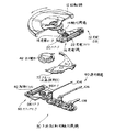
図2には、実施例の電子時計に用いられる発電手段10および運針機構60が示されている。
【0030】
この発電手段10は、時計ケース内の地板に回動自在に取り付けられた半円形の回転錘12と、この回転錘12の回転を増速する輪列機構14と、この輪列機構14により発電ロータ18が回転駆動される発電機16とを含む。
【0031】
そして、使用者が電子時計を装着し腕を動かすと、回転錘12が回転し、そのときの運動エネルギーが図中矢印方向の回転運動となる。この回転錘12の回転は輪列機構14により約100倍に増速されて発電ロータ18に伝達される。そして、N極およびS極の永久磁石から構成された発電ロータ18の高速回転によって、発電ステータ20を介して発電コイル22に鎖交する磁束が変化する。
【0032】
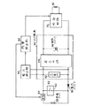
磁束が変化すると、電磁誘導により、発電コイル22から交流電圧が出力され、この交流電圧が、図1に示す整流ダイオード30で整流され、2次電池42を充電する。前記2次電池42は、昇圧回路44、補助コンデンサ46と共に2次電源40を構成する。
【0033】
前記したように、発電機16が作動すると、発電コイル22により2次電池42が充電されていく。実施例では2次電池42の電圧が低くて時計の駆動可動電圧に満たないときは、昇圧回路44により、2次電池42の電圧を時計駆動可能な高電圧に変換し、補助コンデンサ46に蓄電する。そして、補助コンデンサ46を駆動電源として時計回路70は作動する。
【0034】
このとき時計回路70は、振動部にクオーツを用いた発振回路の出力を、分周回路を用いて分周し、その分周出力を駆動回路がカウントし、1秒毎に極性の異なる駆動パルスをステップモータ80の駆動コイル82へ向け出力する。
【0035】
これにより、図2に示すステップモータ80は、駆動パルスが通電される毎にロータ86を回転駆動し、輪列機構90を介し秒針104、分針106、時針108を駆動し、時刻をアナログ表示する。
【0036】
このような電子時計では、2次電池42の過充電を防止するため、過充電防止手段として機能するリミッタ回路50が、前記コイル20と並列に設けられ、充電回路に対するバイパス回路を形成している。前記リミッタ回路50は、バイパス回路をオン,オフするスイッチ素子52を含み、2次電池42の充電電圧が過充電検出用基準値を上回わると、スイッチ素子52をオンするように形成されている。これにより、前記2次電池42に対する充電電流は、このバイパス回路を流れることとなり、2次電池の過充電が防止される。
【0037】
図3には、前記2次電源40における昇圧動作の概念図が示されている。時計回路70を駆動させるには、現在のところ最低1ボルトの電圧が必要となる。電気を蓄える2次電池42は、一般の電池と異なり、充電量に応じて電圧が変化する特性を持っている。充電量が低下して電圧が1ボルトを下回ると、エネルギーそのものはあるものの、電圧が足りないため時計が止まってしまう。なるべく早く時計を始動させ、長く動かし続けるためには、2次電池42に充電したエネルギーを無駄なく使う必要がある。そこで、2次電池42の低い状態の電圧を、時計を駆動させるのに必要なレベルの電圧まで昇圧回路44を用いて昇圧し、コンデンサ46へ充電している。
【0038】
実施例の昇圧回路44は、図3に示すよう、充電により2次電池42の電圧が増加するに従い、これを3倍〜1倍の7段階に亘って昇圧し、補助コンデンサ46を、その電圧が1V以上となるようへ充電する。同様に、2次電池42の電圧が放電等により減衰する場合には、昇圧の場合とは逆に、この電圧を1倍〜3倍の範囲内で7段階にわたって昇圧し、補助コンデンサ46へ充電している。
【0039】
また、このような電子時計では、あとどのくらい動き続けるかを使用者に知らせる必要がある。このため、実施例の電子時計は、2次電池42の現在の充電量、すなわち、時計があとどのくらい動き続けるかの残量を表すインジケータ機能が設けられている。
【0040】
このための残量検出用に、実施例の装置には、2次電池42の電圧を検出する電圧検出部60と、この検出電圧に基づき2次電池42の残量を検出する残量検出部62とが設けられ、残量検出信号が時計回路70に向け出力されるよう構成されている。
【0041】
時計回路70は、図5に示すよう、リューズ右上のボタン92を押すことにより、運針中の秒針を早送りし、その早送り量で2次電池42の残量表示を行なうように形成されいている。すなわち、2次電池42の残量が3日以上ある場合には、30秒、2日以上ある場合には20秒、1日以上ある場合には10秒、3時間以上ある場合には5秒というように秒針を早送りし、その残量表示を行なう。また、残量が3時間以内の場合には、秒針が2秒運針になる機構も備えている。
【0042】
そして、2次電池42の残量が残り少なくなった場合には、使用者は図5に示すようなインジケータ表示を見ながら、2次電池42の充電量が所定の基準量、例えば1日分の充電量となるよう2次電池42に対する急速充電動作を行なう。このような急速充電動作は、図2に示すような発電手段を採用した本実施例の電子時計にあっては、時計本体を振り、回転錘12を回転させることにより行なう。
【0043】
このような2次電池42の残量検出は、通常電圧検出部60で検出された2次電池42の充電電圧に基づいて行われる。このような検出手法は、2次電池42がコンデンサ等で構成されている場合には問題がないが、電極に導電性ポリマーを用いた2次電池である場合には、正確な残量検出を行なうことができない。
【0044】
本実施例は、2次電池42が、このようなポリマー電池である場合に、その残量検出を正確に行なうことを特徴とするものである。
【0045】
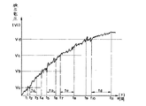
図4には、実施例の電子時計に2次電池として用いられるポリマ電池42の急速充電特性が示されている。このポリマー電池としては、各種のものが知られており、例えばポリアセン電池、Li/PAS電池、PAS−Liコンポジット/PAS電池、PAS/PAS電池等がある。
【0046】
この種の2次電池42は、急速充電を行なうと、実際の充電量より端子電圧が大きく現れる。また、2次電池の充電エネルギーを消費すると、その端子電圧は真の充電量に対応した電圧まで急激に低下する傾向を持つ。したがって、急速充電時には、その端子電圧が上下にふらつくという現象が発生する。
【0047】
残量検出部62は、図5の(A)〜(D)の4つの残量表示に対応して、Va,Vb,Vc,Vdの4つの基準電圧を設定している。
【0048】
従来の残量検出手法では、検出電圧がこの基準電圧を上回った時点で、設定充電量まで充電されたと判断してインジケータ表示を行なうため、正確な残量表示ができなかった。
【0049】
これに対し、実施例の残量検出部62は、検出電圧が基準電圧を所定基準時間連続して上回ったとき、2次電池42がその基準電圧に対応した充電量まで充電されたと判断し、残量検出信号を出力するように構成されている。
【0050】
例えば、2次電池42の残量が0近くなった場合に、急速充電動作を行うと、2次電池42の検出電圧Vi が図4に示すよう、第1の基準電圧Va を最初に上回るのはt1 のタイミングである。しかし、この状態では、その直後に電圧Vi が基準電圧Va を下回るため、3時間分の充電が行われていないと判断する。そして、検出電圧Vi が基準電圧Va を一定基準時間ta の間連続して上回っていることが検出された時点t3 ではじめて、残量検出信号を出力する。このようにして、インジケータには、確実に所定の充電量が充電されたことが確認された段階で、当該残量が表示されることになる。この結果、使用者はインジケータの表示を信頼しながら、急速充電を行なうことが可能となる。
【0051】
このとき、前記基準時間は、各基準電圧に対し全て同一に設定してもよいが、本実施例では、各基準電圧Va,Vb,Vc,Vd毎にそれぞれ固有の値ta ,tb ,tc ,td に設定している。これにより、2次電池の充電レベルに応じてより確実な残量検出を行なうことが可能となる。
【0052】
特に、ポリマー電池の充電時の電圧は、高い電圧になるほど充電効率が悪化する。このため、前記基準時間は、高電圧側の基準時間を長く設定することが好ましい。
【0053】
このため、実施例においては、前記各基準時間が次のように設定される。
ta =10秒
tb =20秒
tc =40秒
td =60秒
なお、図4は、本発明の原理を概括的に説明するための模式的に描いてある。したがって、実際のt3 〜t4 、t6 〜t7 、t8 〜t9 の間隔は、図に示すより十分に長くなる。
【0054】
第2実施例
図6には、本発明の電子時計の好適な第2実施例が示されている。なお、前記第1実施例と対応する部材には同一符号を付してその説明は省略する。
【0055】
本実施例の電子時計では、発電コイル22から2次電池42へ向けた充電回路に充電遮断スイッチ64を設けている。そして、残量検出部62は、2次電池42の残量検出を行なう場合、所定の短時間だけスイッチ64をオフし、2次電池42の充電を強制的に停止させる。
【0056】
このとき、電圧検出部60で検出される2次電池42の検出電圧Vi は、図7に示すように変化する。すなわち、急速充電時に、ta のタイミングでスイッチ64をオフし充電を停止させると、2次電池42の端子電圧Vi は、真の充電量に対応した安定電圧に向けて減衰を開始する。
【0057】
ポリマー電池の特性として、充電を停止してから一定時間経過後の電圧低下が大きい程、実際の充電量は少ないと判断できる。
【0058】
残量検出部62は、このような2次電池42の減衰特性と、検出電圧Vi とから、充電量に対応した2次電池の安定電圧を推定演算し、これを各基準電圧Va 〜Vd と比較する。そして、推定演算された電圧が、いずれかの基準電圧を上回った場合には、当該基準電圧に対応した残量検出信号を時計回路70へ向け出力する。
【0059】
このようにすることによっても、ポリマー電池42の急速充電時における残量検出を正確に行なうことができる。
【0065】
なお、本発明は前記各実施例に限定されるものではなく、本発明の要旨の範囲内で各種の変形実施が可能である。
【0066】
例えば、前記各実施例では、発電手段として図2に示すような発電機16および回転錘12を用いたものを例に取り説明したが、本発明はこれに限らず、各種の発電手段、例えば太陽電池等を用いた電子時計に対しても適用可能であることはいうまでもない。
【0067】
また、前記実施例では、残量表示するインジケータとして、アナログ表示用の秒針を用いる場合を例に取り説明したが、本発明はこれ以外に、例えば、液晶表示タイプの電子時計では、液晶ディスプレイ上に残量表示するようにしてもよい。
【0068】
また、必要に応じ、音声出力用のICを設け、残量を音声出力させてもよい。
【0069】
また、前記実施例では、本発明を腕時計に適用した場合を例に取り説明したが、本発明はこれに限らずこれ以外の各種時計、例えば携帯用時計等にも適用可能であることはいうまでもない。
【0070】
以上説明したように、本発明によれば、
2次電池を急速充電する場合に、2次電池の残量を正確に検出し使用者に知らせることができる電子時計およびその残量検出方法を提供することができる。
【図面の簡単な説明】
【図1】本発明の電子時計の第1実施例の回路図である。
【図2】実施例の電子時計の機械的な構成の要部を示す説明図である。
【図3】実施例の電子時計の昇圧回路の動作を示す説明図である。
【図4】電極に導電性ポリマーを用いた2次電池の急速充電時における充電特性の説明図である。
【図5】残量表示の具体例の説明図である。
【図6】本発明の電子時計の第2実施例の回路図である。
【図7】第2実施例にかかる電子時計の残量検出の原理の概略説明図である。
【符号の説明】
10 発電手段
40 2次電源
42 2次電池
44 昇圧回路
46 補助コンデンサ
60 電圧検出部
62 残量検出部
66 電流計
70 時計回路[0001]
BACKGROUND OF THE INVENTION
The present invention relates to an electronic timepiece equipped with a power generation mechanism and a charging method thereof.
[0002]
[Background]
In a conventional electronic timepiece, electricity serving as a timepiece driving energy source is supplied from a battery. However, batteries need to be replaced when they run out of energy.
[0003]
For this reason, electronic timepieces equipped with a power generation mechanism that generates electrical energy required for timepiece driving have been developed. This type of electronic timepiece uses a solar battery as a power generation mechanism to charge a secondary battery, or a self-winding power generation mechanism that generates power by the natural movement of the user's arm, etc. There are things that charge the battery. These electronic timepieces are not only needing troublesome battery replacement, but also do not generate waste such as used batteries, and thus are attracting attention from the viewpoint of resource saving and environmental protection.
[0004]
Normally, this type of electronic timepiece is provided with a mechanism for detecting and displaying the remaining amount of the secondary battery. When the remaining charge amount of the secondary battery becomes, for example, about 3 hours, 1 day, 2 days, 3 days, etc., this is detected and the remaining amount is displayed to the user. The battery is urged to be charged.
[0005]
In particular, when the remaining amount of the secondary battery becomes extremely small, for example, 3 hours or less, the user needs to perform a quick charging operation for rapidly charging the secondary battery. For example, a battery timepiece using a solar cell as a charging mechanism generates power by directing the solar cell toward a light source and charges a secondary battery. An electronic timepiece equipped with a self-winding power generation mechanism shakes the timepiece to generate electricity and charges the secondary battery. Such a quick charging operation is performed until the remaining amount display reaches a predetermined value. At this time, in order to reliably perform this charging, it is necessary to accurately detect the remaining amount of the secondary battery.
[0006]
[Problems to be solved by the invention]
Usually, the remaining amount of the secondary battery is detected using the terminal voltage. For example, when a capacitor or the like is used as the secondary battery, the terminal voltage accurately reflects the amount of charge, so that the remaining amount can be detected stably only by looking at the terminal voltage.
[0007]
However, in recent years, secondary batteries using conductive polymers as electrodes have come to be used as secondary batteries for watches. In this polymer battery, unlike conventional chemical batteries, charging and discharging are performed by using doping of electrolyte ions, so that the voltage value fluctuates and fluctuates until the terminal voltage stabilizes to a voltage corresponding to the amount of charge. Has characteristics. Therefore, there is a problem in that when the remaining amount is simply detected from the voltage during the quick charge, the remaining amount cannot be detected accurately.
[0008]
In particular, the secondary battery of this type, rapid charging when the terminal voltage rises rapidly to have the property that settles to a stable voltage corresponding to the true charge level after it. For this reason, if the remaining voltage is detected by simply comparing the detected voltage with the reference voltage, a value larger than the actual remaining charge will be erroneously displayed, and the user will be able to perform a quick charging operation when sufficient charging is not performed. There was a problem that often stopped. In this case, since the electronic timepiece is insufficiently charged, there is a problem that the timepiece stops without the user's knowledge.
[0009]
The present invention has been made in view of such a conventional problem, and an object of the present invention is to provide an electronic device that can reliably detect the remaining amount and inform the user when a secondary battery is rapidly charged. It is to provide a timepiece and a method for detecting the remaining amount thereof.
[0010]
[Means for Solving the Problems]
In order to achieve the above object, the present invention provides:
Power generation means for outputting electric energy for charging;
A secondary power source charged by the charging electrical energy;
A clock circuit that operates using the charging energy of the secondary power source;
Voltage detection means for detecting the voltage of the secondary power supply;
A remaining amount detecting means for detecting a remaining amount of the secondary power source based on a detection voltage detected by the voltage detecting means;
An electronic timepiece that informs the detected remaining amount detected by the remaining amount detecting means and urges the user to charge the secondary power source,
The secondary power source includes a secondary battery in which the voltage value fluctuates and fluctuates until the terminal voltage is stabilized at a voltage corresponding to the amount of charge .
The remaining amount detecting means is
When a reference voltage corresponding to the remaining amount of the secondary battery is set in advance and the detected voltage exceeds the reference voltage continuously for a predetermined reference time, the remaining amount of the secondary battery corresponding to the reference voltage is detected. It is formed to output a signal.
[0011]
In the present invention,
The remaining amount detecting means is
When a plurality of reference voltages corresponding to the remaining amount of the secondary battery are set in advance and the detection voltage exceeds the predetermined reference voltage for a predetermined reference time continuously, a detection signal for the remaining amount corresponding to the reference voltage is output. It is characterized by that.
[0012]
In the present invention,
The remaining amount detecting means is
The reference time is set for each reference voltage.
[0016]
The secondary power source is charged by charging electric energy output from the power generation means. The clock circuit operates using the charging energy of the secondary power source.
[0017]
The remaining amount detecting means detects the remaining amount of the secondary power source based on the voltage of the secondary power source and notifies the user.
[0018]
Thus, when the remaining amount of detection decreases, the user performs a quick charging operation on the secondary power supply until the remaining amount returns to a predetermined level.
[0019]
At this time, if the voltage at the time of quick charging of the secondary battery included in the secondary power source takes time to fluctuate to a voltage corresponding to the amount of charge and fluctuates, A corresponding reference voltage is set in advance, and only when the detected voltage exceeds the reference voltage continuously for a predetermined reference time, it is determined that the secondary battery is charged to at least a charge amount corresponding to the reference voltage, and the remaining voltage is determined. It is the structure which outputs the detection signal of quantity. Thereby, a user can be correctly notified of the remaining amount at the time of quick charge of a secondary battery.
[0020]
In addition, according to the present invention, a plurality of reference voltages are set corresponding to the remaining amount of the secondary battery such as 3 hours, 1 day, 2 days, etc. When a predetermined reference time is exceeded, a corresponding remaining amount detection signal is output. Thereby, the charge amount of a secondary battery can be correctly displayed over many steps at the time of quick charge.
[0021]
In addition, according to the present invention, the remaining time of the secondary battery can be detected more accurately by setting the reference time for each reference voltage.
[0022]
In particular, the charging efficiency of the polymer battery deteriorates as the voltage increases. For this reason, it is preferable that the reference time is set longer than the reference time on the high voltage side.
[0023]
Moreover, according to this invention, the charge interruption | blocking switch means which stops the charge to a secondary power supply from an electric power generation means is included, and charge of a secondary power supply is stopped temporarily at the time of rapid charge. Based on the attenuation characteristic of the detected voltage at this time, the remaining amount of the secondary battery is detected.
[0024]
That is, in a secondary battery having a characteristic that the voltage level is attenuated to a voltage corresponding to the true charge amount when the quick charge is stopped, the true remaining amount of the secondary battery is determined by detecting the attenuation characteristic at this time. It can be predicted accurately.
[0027]
Further, according to the present invention, it is possible to obtain a remaining amount detection method capable of accurately detecting the remaining amount of the secondary battery at the time of rapid charging.
[0028]
DETAILED DESCRIPTION OF THE INVENTION
Next, the case where the present invention is applied to an analog display type electronic wristwatch will be described in detail.
[0029]
First embodiment Fig. 2 shows a power generation means 10 and a
[0030]
The power generation means 10 includes a semicircular
[0031]
When the user wears an electronic timepiece and moves his arm, the
[0032]
When the magnetic flux changes, an AC voltage is output from the power generation coil 22 by electromagnetic induction, and this AC voltage is rectified by the rectifier diode 30 shown in FIG. 1 to charge the
[0033]
As described above, when the generator 16 is activated, the
[0034]
At this time, the
[0035]
As a result, the
[0036]
In such an electronic timepiece, in order to prevent overcharge of the
[0037]
FIG. 3 shows a conceptual diagram of the step-up operation in the secondary power source 40. To drive the
[0038]
As shown in FIG. 3, the
[0039]
Moreover, in such an electronic timepiece, it is necessary to inform the user how long it will continue to move. For this reason, the electronic timepiece of the embodiment is provided with an indicator function that indicates the current charge amount of the
[0040]
For this purpose, the device of the embodiment includes a
[0041]
As shown in FIG. 5, the
[0042]
When the remaining amount of the
[0043]
Such remaining amount detection of the
[0044]
This embodiment is characterized in that when the
[0045]
FIG. 4 shows the quick charge characteristics of a
[0046]
When this type of
[0047]
The remaining
[0048]
In the conventional remaining amount detection method, when the detected voltage exceeds the reference voltage, it is determined that the battery has been charged up to the set charge amount, and an indicator is displayed, so that an accurate remaining amount display cannot be performed.
[0049]
On the other hand, when the detection voltage exceeds the reference voltage for a predetermined reference time continuously, the remaining
[0050]
For example, when the quick charge operation is performed when the remaining amount of the
[0051]
At this time, the reference times may all be set to be the same for each reference voltage. In this embodiment, however, each of the reference voltages Va, Vb, Vc, Vd has its own unique values ta, tb, tc, td is set. As a result, the remaining amount can be more reliably detected according to the charge level of the secondary battery.
[0052]
In particular, the charging efficiency of the polymer battery deteriorates as the voltage increases. For this reason, it is preferable that the reference time is set longer than the reference time on the high voltage side.
[0053]
For this reason, in the embodiment, the reference times are set as follows.
ta = 10 sec. tb = 20 sec. tc = 40 sec. td = 60 sec. FIG. 4 is schematically drawn for explaining the principle of the present invention. Therefore, the actual intervals between t3 to t4, t6 to t7, and t8 to t9 are sufficiently longer than shown in the figure.
[0054]
Second embodiment Fig. 6 shows a second preferred embodiment of the electronic timepiece of the invention. In addition, the same code | symbol is attached | subjected to the member corresponding to the said 1st Example, and the description is abbreviate | omitted.
[0055]
In the electronic timepiece of the present embodiment, the
[0056]
At this time, the detection voltage Vi of the
[0057]
As a characteristic of the polymer battery, it can be determined that the actual charge amount is smaller as the voltage drop after a certain time elapses after the charge is stopped.
[0058]
The remaining
[0059]
This also makes it possible to accurately detect the remaining amount when the
[0065]
The present invention is not limited to the embodiments described above, and various modifications can be made within the scope of the gist of the present invention.
[0066]
For example, in each of the above embodiments, the generator 16 and the
[0067]
Further, in the above embodiment, the case where the second hand for analog display is used as an indicator for displaying the remaining amount has been described as an example. However, the present invention is not limited to this. For example, in an electronic timepiece of a liquid crystal display type, The remaining amount may be displayed.
[0068]
Further, if necessary, an audio output IC may be provided to output the remaining amount as audio.
[0069]
In the above-described embodiment, the case where the present invention is applied to a wristwatch has been described as an example. However, the present invention is not limited to this and can be applied to various other types of watches such as portable watches. Not too long.
[0070]
As explained above, according to the present invention,
It is possible to provide an electronic timepiece capable of accurately detecting the remaining amount of the secondary battery and notifying the user when the secondary battery is rapidly charged, and a method for detecting the remaining amount.
[Brief description of the drawings]
FIG. 1 is a circuit diagram of a first embodiment of an electronic timepiece according to the invention.
FIG. 2 is an explanatory diagram illustrating a main part of a mechanical configuration of the electronic timepiece according to the embodiment.
FIG. 3 is an explanatory diagram illustrating an operation of the booster circuit of the electronic timepiece according to the embodiment.
FIG. 4 is an explanatory diagram of charging characteristics at the time of rapid charging of a secondary battery using a conductive polymer as an electrode.
FIG. 5 is an explanatory diagram of a specific example of remaining amount display.
FIG. 6 is a circuit diagram of a second embodiment of the electronic timepiece of the invention.
FIG. 7 is a schematic explanatory diagram of the principle of detecting the remaining amount of the electronic timepiece according to the second embodiment.
[Explanation of symbols]
DESCRIPTION OF SYMBOLS 10 Electric power generation means 40
Claims (3)
前記充電用電気エネルギーにより充電される2次電源と、
前記2次電源の充電エネルギーを用いて作動する時計回路と、
前記2次電源の電圧を検出する電圧検出手段と、
前記電圧検出手段により検出した検出電圧に基づき前記2次電源の残量検出を行う残量検出手段と、
を含み、前記残量検出手段により検出した検出残量を知らせ、2次電源の充電を使用者に促す電子時計であって、
前記2次電源は、端子電圧が充電量に応じた電圧に安定するまで、電圧値がふらついて変動する2次電池を含み、
前記残量検出手段は、
予め前記2次電池の残量に対応した基準電圧が設定され、前記検出電圧が前記基準電圧を所定基準時間連続して上回ったとき、前記基準電圧に対応した前記2次電池の残量の検出信号を出力するよう形成されたことを特徴とする電子時計。Power generation means for outputting electric energy for charging;
A secondary power source charged by the charging electrical energy;
A clock circuit that operates using the charging energy of the secondary power source;
Voltage detection means for detecting the voltage of the secondary power supply;
A remaining amount detecting means for detecting a remaining amount of the secondary power source based on a detection voltage detected by the voltage detecting means;
An electronic timepiece that informs the detected remaining amount detected by the remaining amount detecting means and urges the user to charge the secondary power source,
The secondary power source includes a secondary battery in which the voltage value fluctuates and fluctuates until the terminal voltage is stabilized at a voltage corresponding to the amount of charge.
The remaining amount detecting means is
When a reference voltage corresponding to the remaining amount of the secondary battery is set in advance and the detected voltage exceeds the reference voltage continuously for a predetermined reference time, the remaining amount of the secondary battery corresponding to the reference voltage is detected. An electronic timepiece formed to output a signal.
前記残量検出手段は、
予め前記2次電池の残量に対応した複数の基準電圧が設定され、前記検出電圧が所定の前記基準電圧を所定基準時間連続して上回ったとき、前記基準電圧に対応した前記2次電池の残量の検出信号を出力することを特徴とする電子時計。In claim 1,
The remaining amount detecting means is
A plurality of reference voltages corresponding to the remaining amount of the secondary battery are set in advance, and when the detected voltage exceeds the predetermined reference voltage continuously for a predetermined reference time, the secondary battery corresponding to the reference voltage An electronic timepiece that outputs a remaining amount detection signal.
前記残量検出手段は、
前記基準時間を、各前記基準電圧毎に設定したことを特徴とする電子時計。In claim 2,
The remaining amount detecting means is
An electronic timepiece characterized in that the reference time is set for each reference voltage.
Priority Applications (1)
| Application Number | Priority Date | Filing Date | Title |
|---|---|---|---|
| JP15620799A JP3623397B2 (en) | 1994-05-13 | 1999-06-03 | Electronic watch and its charging method |
Applications Claiming Priority (3)
| Application Number | Priority Date | Filing Date | Title |
|---|---|---|---|
| JP6124144A JP2973273B2 (en) | 1994-05-13 | 1994-05-13 | Electronic clock and charging method thereof |
| JP15620799A JP3623397B2 (en) | 1994-05-13 | 1999-06-03 | Electronic watch and its charging method |
| JP2002091431A JP3864107B2 (en) | 1994-05-13 | 2002-03-28 | Electronic clock |
Related Parent Applications (1)
| Application Number | Title | Priority Date | Filing Date |
|---|---|---|---|
| JP6124144A Division JP2973273B2 (en) | 1994-05-13 | 1994-05-13 | Electronic clock and charging method thereof |
Related Child Applications (1)
| Application Number | Title | Priority Date | Filing Date |
|---|---|---|---|
| JP2002091431A Division JP3864107B2 (en) | 1994-05-13 | 2002-03-28 | Electronic clock |
Publications (2)
| Publication Number | Publication Date |
|---|---|
| JPH11352253A JPH11352253A (en) | 1999-12-24 |
| JP3623397B2 true JP3623397B2 (en) | 2005-02-23 |
Family
ID=50496539
Family Applications (4)
| Application Number | Title | Priority Date | Filing Date |
|---|---|---|---|
| JP6124144A Expired - Fee Related JP2973273B2 (en) | 1994-05-13 | 1994-05-13 | Electronic clock and charging method thereof |
| JP09031597A Expired - Fee Related JP3185706B2 (en) | 1994-05-13 | 1997-03-25 | Electronic clock |
| JP15620799A Expired - Fee Related JP3623397B2 (en) | 1994-05-13 | 1999-06-03 | Electronic watch and its charging method |
| JP2002091431A Expired - Fee Related JP3864107B2 (en) | 1994-05-13 | 2002-03-28 | Electronic clock |
Family Applications Before (2)
| Application Number | Title | Priority Date | Filing Date |
|---|---|---|---|
| JP6124144A Expired - Fee Related JP2973273B2 (en) | 1994-05-13 | 1994-05-13 | Electronic clock and charging method thereof |
| JP09031597A Expired - Fee Related JP3185706B2 (en) | 1994-05-13 | 1997-03-25 | Electronic clock |
Family Applications After (1)
| Application Number | Title | Priority Date | Filing Date |
|---|---|---|---|
| JP2002091431A Expired - Fee Related JP3864107B2 (en) | 1994-05-13 | 2002-03-28 | Electronic clock |
Country Status (4)
| Country | Link |
|---|---|
| US (1) | US5740132A (en) |
| EP (1) | EP0685777B1 (en) |
| JP (4) | JP2973273B2 (en) |
| DE (1) | DE69522741T2 (en) |
Families Citing this family (23)
| Publication number | Priority date | Publication date | Assignee | Title |
|---|---|---|---|---|
| JP3718725B2 (en) * | 1996-03-13 | 2005-11-24 | シチズン時計株式会社 | Power supply for electronic watch |
| JP3541601B2 (en) * | 1997-02-07 | 2004-07-14 | セイコーエプソン株式会社 | Control device for stepping motor, control method thereof, and timing device |
| JP3963554B2 (en) * | 1997-06-17 | 2007-08-22 | セイコーエプソン株式会社 | Electronic device, watch, and power consumption control method for electronic device |
| JP3816197B2 (en) * | 1997-07-18 | 2006-08-30 | シチズン時計株式会社 | Rechargeable electronic watch |
| JP3650269B2 (en) * | 1997-10-07 | 2005-05-18 | セイコーインスツル株式会社 | Electronic timepiece with power generation element |
| JPH11218587A (en) | 1997-11-25 | 1999-08-10 | Seiko Instruments Inc | Electronic timepiece with thermoelectric element |
| EP0996043B1 (en) * | 1998-04-21 | 2009-03-11 | Seiko Epson Corporation | Time measuring device |
| EP0996042B1 (en) | 1998-04-21 | 2007-05-30 | Seiko Epson Corporation | Clock and time measuring method |
| DE69942553D1 (en) | 1998-04-21 | 2010-08-12 | Seiko Epson Corp | Apparatus and method for timing |
| JPH11338963A (en) * | 1998-05-29 | 1999-12-10 | Toshiba Tec Corp | Symbol reader |
| JP3601375B2 (en) * | 1998-12-14 | 2004-12-15 | セイコーエプソン株式会社 | Portable electronic device and method of controlling portable electronic device |
| CN1145859C (en) | 1999-01-06 | 2004-04-14 | 精工爱普生株式会社 | Electronic device and control method thereof |
| US7126569B2 (en) * | 1999-03-23 | 2006-10-24 | Minolta Co., Ltd. | Liquid crystal display device |
| JP3674466B2 (en) * | 1999-11-24 | 2005-07-20 | セイコーエプソン株式会社 | Voltage detection device, battery remaining amount detection device, voltage detection method, battery remaining amount detection method, electronic timepiece, and electronic device |
| JP4694681B2 (en) * | 1999-11-26 | 2011-06-08 | セイコーインスツル株式会社 | Ultrasonic motor and electronic device with ultrasonic motor |
| JP2002257955A (en) | 2000-12-25 | 2002-09-11 | Seiko Epson Corp | Wristwatch device with communication function, information display method, control program and recording medium |
| US6930848B1 (en) | 2002-06-28 | 2005-08-16 | Western Digital Technologies, Inc. | Back EMF voltage transducer/generator to convert mechanical energy to electrical energy for use in small disk drives |
| US7327638B2 (en) * | 2002-09-24 | 2008-02-05 | Citizen Holdings Co., Ltd. | Electronic timepiece |
| JP5205086B2 (en) * | 2008-03-17 | 2013-06-05 | シチズン時計株式会社 | Electronic clock |
| US20100331974A1 (en) * | 2009-06-26 | 2010-12-30 | Schaper Jr Dale Thomas | Intraocular Kinetic Power Generator |
| JP5953722B2 (en) * | 2011-12-05 | 2016-07-20 | セイコーエプソン株式会社 | Electronic clock |
| JP5508560B2 (en) * | 2013-02-18 | 2014-06-04 | シチズン時計株式会社 | Electronic clock |
| JP6729616B2 (en) * | 2018-03-08 | 2020-07-22 | カシオ計算機株式会社 | Electronic device, power feeding control method, and program |
Family Cites Families (8)
| Publication number | Priority date | Publication date | Assignee | Title |
|---|---|---|---|---|
| JPS5169664A (en) * | 1974-12-13 | 1976-06-16 | Suwa Seikosha Kk | Denshidokei |
| JPS5575665A (en) * | 1978-12-04 | 1980-06-07 | Toshiba Corp | Detection circuit for battery capacity |
| JPS61209372A (en) * | 1985-03-14 | 1986-09-17 | Matsushita Electric Works Ltd | Circuit for confirming residual power quantity in battery |
| JP2622540B2 (en) * | 1985-04-10 | 1997-06-18 | セイコーエプソン株式会社 | Electronic clock |
| US4785436A (en) * | 1986-02-14 | 1988-11-15 | Citizen Watch Co., Ltd. | Photovoltaic electronic timepiece |
| DE4041696C1 (en) * | 1990-12-24 | 1992-03-26 | Braun Ag, 6000 Frankfurt, De | Charge state monitor for power source of electronic timepiece - has output voltage measurer connected to counter for lower and upper thresholds |
| JP2998331B2 (en) * | 1991-09-19 | 2000-01-11 | セイコーエプソン株式会社 | Analog electronic clock |
| JPH06308206A (en) * | 1993-04-28 | 1994-11-04 | Mitsubishi Electric Corp | Battery power remaining monitoring method |
-
1994
- 1994-05-13 JP JP6124144A patent/JP2973273B2/en not_active Expired - Fee Related
-
1995
- 1995-05-11 US US08/439,527 patent/US5740132A/en not_active Expired - Fee Related
- 1995-05-15 EP EP95303247A patent/EP0685777B1/en not_active Expired - Lifetime
- 1995-05-15 DE DE69522741T patent/DE69522741T2/en not_active Expired - Fee Related
-
1997
- 1997-03-25 JP JP09031597A patent/JP3185706B2/en not_active Expired - Fee Related
-
1999
- 1999-06-03 JP JP15620799A patent/JP3623397B2/en not_active Expired - Fee Related
-
2002
- 2002-03-28 JP JP2002091431A patent/JP3864107B2/en not_active Expired - Fee Related
Also Published As
| Publication number | Publication date |
|---|---|
| JP3864107B2 (en) | 2006-12-27 |
| EP0685777A3 (en) | 1997-02-05 |
| JP2973273B2 (en) | 1999-11-08 |
| JPH1026675A (en) | 1998-01-27 |
| EP0685777B1 (en) | 2001-09-19 |
| DE69522741T2 (en) | 2002-05-29 |
| JPH07306275A (en) | 1995-11-21 |
| DE69522741D1 (en) | 2001-10-25 |
| JP3185706B2 (en) | 2001-07-11 |
| JPH11352253A (en) | 1999-12-24 |
| EP0685777A2 (en) | 1995-12-06 |
| JP2002372588A (en) | 2002-12-26 |
| HK1013690A1 (en) | 1999-09-03 |
| US5740132A (en) | 1998-04-14 |
Similar Documents
| Publication | Publication Date | Title |
|---|---|---|
| JP3623397B2 (en) | Electronic watch and its charging method | |
| US5751666A (en) | Electronic timepiece comprising a generator driven by a spring barrel | |
| EP1018675B1 (en) | Power supply device, control method for the power supply device, portable electronic device, timepiece, and control method for the timepiece | |
| US6396772B1 (en) | Electronic apparatus and control method for electronic apparatus | |
| JP3534071B2 (en) | Electronic device and control method for electronic device | |
| US6278663B1 (en) | Electronic apparatus and control method for electronic apparatus | |
| EP1055981B1 (en) | Electronically controlled mechanical watch and method of preventing overcharge | |
| JP3816197B2 (en) | Rechargeable electronic watch | |
| US6343051B1 (en) | Portable electronic device and control method for the portable electronic device | |
| JPH10177079A (en) | Watch provided with generator | |
| US5822278A (en) | Electronic timepiece and method of charging the same | |
| JP4234227B2 (en) | Electronic timepiece powered by a generator driven by a mechanical power source | |
| JP3654018B2 (en) | Timing device and control method of timing device | |
| US11656580B2 (en) | Electronic watch | |
| JP3024482B2 (en) | Analog electronic clock and charging method thereof | |
| JP2000214271A (en) | Electronic control electronic device, electronic control mechanical clock, and control method for electronic control electronic device | |
| JP2924639B2 (en) | Analog electronic clock and charging method thereof | |
| HK1013690B (en) | Electronic timepiece and method of charging the same | |
| CN118625629A (en) | Electronically controlled mechanical clocks | |
| JP3906715B2 (en) | Electronic device and control method of electronic device | |
| HK1033004A (en) | Electronically controlled mechanical watch and method of preventing overcharge | |
| HK1028819B (en) | Portable electronic device and control method for the same |
Legal Events
| Date | Code | Title | Description |
|---|---|---|---|
| A02 | Decision of refusal |
Free format text: JAPANESE INTERMEDIATE CODE: A02 Effective date: 20020129 |
|
| A61 | First payment of annual fees (during grant procedure) |
Free format text: JAPANESE INTERMEDIATE CODE: A61 Effective date: 20041124 |
|
| R150 | Certificate of patent or registration of utility model |
Free format text: JAPANESE INTERMEDIATE CODE: R150 |
|
| FPAY | Renewal fee payment (event date is renewal date of database) |
Free format text: PAYMENT UNTIL: 20081203 Year of fee payment: 4 |
|
| FPAY | Renewal fee payment (event date is renewal date of database) |
Free format text: PAYMENT UNTIL: 20091203 Year of fee payment: 5 |
|
| FPAY | Renewal fee payment (event date is renewal date of database) |
Free format text: PAYMENT UNTIL: 20101203 Year of fee payment: 6 |
|
| FPAY | Renewal fee payment (event date is renewal date of database) |
Free format text: PAYMENT UNTIL: 20101203 Year of fee payment: 6 |
|
| FPAY | Renewal fee payment (event date is renewal date of database) |
Free format text: PAYMENT UNTIL: 20111203 Year of fee payment: 7 |
|
| FPAY | Renewal fee payment (event date is renewal date of database) |
Free format text: PAYMENT UNTIL: 20111203 Year of fee payment: 7 |
|
| FPAY | Renewal fee payment (event date is renewal date of database) |
Free format text: PAYMENT UNTIL: 20121203 Year of fee payment: 8 |
|
| LAPS | Cancellation because of no payment of annual fees |