JP3622801B2 - Lubrication monitoring device - Google Patents
Lubrication monitoring device Download PDFInfo
- Publication number
- JP3622801B2 JP3622801B2 JP32522095A JP32522095A JP3622801B2 JP 3622801 B2 JP3622801 B2 JP 3622801B2 JP 32522095 A JP32522095 A JP 32522095A JP 32522095 A JP32522095 A JP 32522095A JP 3622801 B2 JP3622801 B2 JP 3622801B2
- Authority
- JP
- Japan
- Prior art keywords
- refueling
- screen
- display
- fueling
- switch
- Prior art date
- Legal status (The legal status is an assumption and is not a legal conclusion. Google has not performed a legal analysis and makes no representation as to the accuracy of the status listed.)
- Expired - Fee Related
Links
Images


Description
【0001】
【発明が属する技術分野】
本発明は、給油所の複数台の給油機を含む多数の機器を集中管理する給油監視装置に関するものである。
【0002】
【従来の技術】
従来、複数台の給油機を1台のディスプレイにより管理する制御装置として、例えば、特開平6−162793号公報には、複数の給油機に対応した複数の区画に分割されたタッチパネルにより給油機からの信号を表示させるとともに、タッチパネルからの信号に対応した指令を各給油機に出力する給油機制御装置に関する技術が開示されている。
【0003】
【発明が解決しようとする課題】
しかしながら、従来の給油機制御装置では、タッチパネルにより各給油機を制御することができるが、1人のオペレータで給油許可を与えるときなどの各給油機の使用状態を監視するには不便であり、また、給油所における他の複数の機器を集中管理できるものではない。さらに、従来の多くの給油所では既にPOS端末が導入されているが、その端末を利用しながら将来のセルフサービスの運営に必要な機器を有機的に統合し1人のオペレータで集中管理できることが要望されている。
【0004】
そこで本発明は、給油所の運営に必要な機器を1人のオペレータで集中管理でき、かつ操作性が向上できる給油監視装置を提供することを目的とする。
【0005】
【課題を解決するための手段】
上記目的を達成するために、本発明の給油監視装置は、複数台の給油機に対応して複数の区画に分割された給油状態と給油情報を表示するための表示領域を有するモニタリング画面を表示モニターに表示するとともに、前記給油機周辺の映像を得るビデオカメラの映像画面を前記表示モニターのモニタリング画面に重ねて選択的に表示し、前記モニタリング画面上のカーソル位置のスイッチ手段の操作により前記複数台の給油機を管理する給油監視装置において、前記給油機の給油状態に応じて前記スイッチ手段による次の操作を行うためのカーソル位置にカーソルを移動させるカーソル位置制御手段と、前記スイッチ手段によるスイッチ操作を判定するスイッチ判定手段と、前記スイッチ判定手段の判定結果により、前記給油機に指令を出力する指令出力手段及び表示モニターに表示する画面を選択する表示画像選択手段とを有し、かつ前記カーソル位置制御手段は、前記給油機からの給油要求信号によりカーソルが前記ビデオカメラの映像画面を選択する位置に移動し、前記表示画像選択手段が前記ビデオカメラの映像画面を選択して前記モニタリング画面に重ねて表示することを特徴とするものである。表示モニターに表示されるモニタリング画面により、1人のオペレータが複数台の給油機を集中管理でき、かつカーソル位置制御手段が次の操作をするための位置に移動していることで、操作性が向上する。
【0007】
【発明の実施の形態】
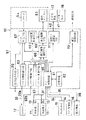
以下、本発明を図示の実施形態により具体的に説明する。図1は本発明の給油監視装置におけるコンピュータが奏すべき機能を示すブロック図、図2は本発明の給油監視装置を用いた給油所の一例を示す構成図、図3は本発明の給油監視装置の外観イメージを説明する斜視図である。
【0008】
これらの図において、本実施形態の給油監視装置10は、給油所に設けられる複数台の給油機11,…、給油状況の監視のためのビデオカメラ12及びインターフォン13、タンク制御部14、各種セキュリティセンサ15、その他の機器16、POS端末17、プリンタ18あるいは通信回線との接続により、給油所の運営に必要な機器を有機的に統合し1人のオペレータが集中管理できるものである。
【0009】
図2に示すように、給油機11は、例えば、ハイオクタンガソリン、レギュラーガソリンあるいは軽油等のいずれかを給油できる装置であり、その本体内にポンプモータ21によって駆動される給油ポンプ22が配置されている。この給油ポンプ22は、その吸入口側が地下タンクに連通するパイプに接続され、その吐出口側が流量パルス発信器23を有する流量計24に接続されている。この流量計24の出口側は、電磁バルブ72を介して本体の側面に導出され、その部分に給油ホース25の一端部が接続されている。この給油ホース25の先端部には、給油ノズル26が接続され、その給油ノズル26が本体の側面に設けられたノズル掛け27に着脱自在に掛けられるようになっている。ノズル掛け27の近傍には、給油ノズル26の脱着によりオン・オフするノズルスイッチ28が設けられている。また、本体の内部には、ノズルスイッチ28の信号あるいは後に説明する給油設定の信号によりポンプモータ21及び電磁バルブ72の動作を制御するとともに、流量パルス発信器23から出力されるパルスにより流量を積算し、表示器29の給油量の表示を制御する制御装置30が設けられている。さらに、この制御装置30と給油監視装置10との間は、制御装置30からノズルスイッチ28のオン・オフ信号及び給油量に関する信号を給油監視装置10へ転送し、また給油監視装置10から給油装置11を制御するための信号を制御装置30へ転送するためのケーブル31で接続されている。
【0010】
ビデオカメラ12は、使用される給油機11周辺の映像を得るためのカメラであり、カメラ本体部12aと映像画面の切換機構12bとを有する。このようなビデオカメラ12は、各給油機11毎に設けられていてもよいが、複数台の給油機11のいずれかに向きを変えることができるようにしてもよい。したがって、切換機構12bは、必要な部分の映像を得るためにカメラ本体部12aの向きを変えたり、ズームアップできる機構を含むものである。ビデオカメラ12と給油監視装置10との間は、ビデオカメラ12の切換制御信号あるいは映像信号等を転送するためのケーブル32で接続されている。また、インターフォン13は、各給油機11を使用する顧客とオペレータとの間の通話を可能とするものであり、例えば、各給油機11の本体側面と事務所等のオペレータがいる近傍に通話部が設けられており、通話部を制御するための信号を転送するケーブル33で給油監視装置10と接続されている。
【0011】
セキュリティセンサ15は、火災検知、人間検知あるいはスプリンクラー作動等のために各所に設けられた安全検知用のセンサであり、検知信号を給油監視装置10に転送するケーブル34が設けられている。タンク制御部14は、給油に必要な油を貯える地下タンク37等の制御部であり、地下タンク37は油面計や油の漏洩検知センサが設けられ、タンク制御部14により油面や漏洩が検知され、その検知信号がケーブル35により給油監視装置10に転送される。また、タンク制御部37と荷卸のための荷卸端末38と間は、荷卸指示と荷卸データを転送するケーブル39で接続されている。荷卸端末38は、地下タンク37の液面計に基づいてオーバーフロー等を防止するストップ弁42を制御する。さらに、他の機器16は、例えば、洗車機やアウトプットターミナル(OPT)等であり、それぞれ給油監視装置10との間に信号を伝達するケーブル36で接続されている。
【0012】
POS端末17は、販売情報や仕入れ等の段階で発生する各種情報をそれぞれの目的に応じて利用できる情報に処理、加工する販売情報時点管理を行う端末であり、給油監視装置10との間を情報伝送するためのケーブル40で接続されている。プリンタ18は、オーダーリストや各種データを印字するためのものであり、POS端末17との間を印字データ転送のためのケーブル41で接続されている。また、給油監視装置10は、モデム等を介して通信回線と接続されており、オートダイヤル機能及びオートFAX機能により、在庫情報、荷卸情報の送信、モデムを介して映像情報等のマルチメディア情報の受信、本社等にビデオカメラの映像情報を送信するリモート監視、ホストコンピュータとの通信等の機能を備えている。
【0013】
図3に示すように、給油所の事務所等には、1人のオペレータにより操作される給油監視装置10が配置されており、デスク51の下部には給油監視装置10の中心部を構成するコンピュータ本体52が配置され、デスク51の上部には表示モニター53とマウス54が配置されている。また、給油監視装置10近傍に隣接してデスク55が配置され、その上部にはPOS端末17が配置され、その下部にはプリンタ18が配置されている。同図において、符号56はキャッシュドロアーである。
【0014】
給油監視装置10は、そのコンピュータ本体52に実現すべき機能を備えており、図1に示すように、データ制御手段61、記憶手段62、ビデオ切換制御手段63、ビデオデータ制御手段64、インターフォン制御手段65、表示画面選択手段66、スイッチ判定手段67、カーソル位置制御手段68、表示駆動手段69、指令出力手段70、販売データ送受信手段71及び通信制御手段73等から構成される。
【0015】
データ制御手段61は、複数台の給油機11,…の制御装置30からケーブル31を介して送信されてくるノズルスイッチのオン・オフ信号及び給油量データ等、セキュリティセンサ15からケーブル34を介して送信されてくる検出信号、タンク制御部14で検出される油面データ、漏洩検知信号及び荷卸端末38から送信されてくる荷卸データ、他の機器16から送信されてくるデータを取り込み、そのデータを必要により記憶手段62に格納し、また各部に指示を与えたりデータを送信する部分である。記憶手段62は、各種の処理を行うためのプログラムを格納したり、上述の取り込まれたデータを一時的に格納したり、表示モニター52に表示すべき基本画面等の画像データあるいはその基本画面に表示するシンボルや文字等の画像データを格納している部分である。ビデオ切換制御手段63は、マウス53のクリックによるスイッチ判定部67の判定結果によりビデオカメラ12の切換機構12bを制御するための画面切換信号をケーブル32aを介して出力する部分である。ビデオデータ制御手段64は、ビデオカメラ12のカメラ本体部12aからケーブル32bを介して送信されてくる映像データを取り込み、表示画像選択手段66に送信する部分である。インターフォン制御手段65は、使用中の給油機11に設けられているインターフォン13と通話を可能にするための制御信号をケーブル33を介して送信する部分である。表示画像選択手段66は、スイッチ判定手段67からの判定結果あるいはデータ制御手段61の制御の元に、表示モニター53に表示すべき画像データを選択する部分である。スイッチ判定手段67は、マウス54のクリックによるスイッチ操作を判定する部分である。カーソル位置制御手段68は、給油機11を含む外部の機器の状態、あるいは各種のセンサの検出信号に基づいて、次に操作するスイッチ動作のためのカーソル位置に移動させる部分である。表示駆動手段69は、表示画像選択手段66で選択された画像を表示モニター53に表示させる部分である。指令出力手段70は、スイッチ判定手段67の判定結果に基づいて、給油機11へ給油許可あるいは緊急停止を指示する部分である。販売データ送受信手段71は、給油機11の給油量等に関する販売データをケーブル40を介してPOS端末17に転送したり、POS端末17の給油設定に関する情報をブル40を介して給油監視装置10に転送する部分である。通信制御手段73は、モデム等により通信回線に接続し通信を制御する部分である。
【0016】
次に、給油監視装置10の表示モニター53に表示される画面例を説明する。図4乃至図7は本発明の給油監視装置の画面例を示す図であり、図4は基本画面を示す図、図5は給油機のモニタリング画面を示す図、図6は油面計画面を示す図、図7はPOSモード画面を示す図である。
【0017】
表示モニター53に表示される画面は、複数の情報を同時に表示するものであり、基本画面は図4に示すように、複数台の給油機11,…の給油状態と給油情報を表示するための給油機モニタリング画面81と、各機器のステイタス表示あるいはモード切換スイッチを表示するための機器ステイタス表示画面82とから構成されている。
【0018】
給油機モニタリング画面81は、表示モニター53の表示画面が、給油機11,…に対応させてその給油状態と給油情報を表示するために複数の区画に分割されており、各区画には各給油機11の機械番号を表示する領域81aと、レギュラーガソリン、ハイオクタンガソリンあるいは軽油等の油の種類を表示する領域81bと、給油状態を示すシンボル等を表示する領域81cと、給油量を表示する領域81dとを有する。この給油機モニタリング画面81の表示例では、機械番号が1番〜12番の12台の給油機11,…に対応して、12個の区画に分割され、それぞれの区画の各領域に機械番号や油の種類が表示されている。なお、図4の表示例では、給油機11,…のいずれも使用されていないため、給油状態を示すシンボル等を表示する領域81cや給油量を表示する領域81dには何も表示されていない。
【0019】
機器ステイタス表示画面82は、各機器の状態表示あるいはモード切換スイッチを表示する画面であり、給油機モニタリング画面81の下部が複数の区画に区分されており、それぞれの領域にステイタスを代表するシンボルあるいは文字等が表示されている。この機器ステイタス表示画面82は、例えば、販売データをPOS端末17へ転送するときに使用するPOS等の文字を表示した領域82a、給油機の給油を停止するときに使用する停止シンボルを表示した領域82b、ビデオカメラの映像表示に切換えるときに使用するカメラのシンボルを表示した領域82c、インターフォンの通話状態に切換えるときに使用するインターフォンのシンボルを表示した領域82d、地下タンクの在庫不足を表示するためのタンクのシンボルを表示した領域82e、セキュリティセンサ15からの検出を知らせる文字を表示した領域82f及びオートダイヤルの使用を示す電話のシンボルを表示した領域82gを有する。基本画面は、記憶手段62に格納されている画像データをデータ制御手段61で読み出し、表示画面選択手段66及び表示駆動手段69を介して表示モニター52に表示されるようになっている。
【0020】
給油機のモニタリング画面81は図5に示すように、使用中の給油機に対応する区画に必要な情報が表示される。例えば、給油機モニタリング画面81において、ハイオクタンガソリンを給油する機械番号5番の給油機は、給油ノズルが外されて給油要求が出されている状態で領域81cに給油ノズルの外れを示すシンボルが表示され、軽油を給油する機械番号3番の給油機は、給油中で領域81cに給油ノズルの給油中を示すシンボルと給油途中の給油量が領域81dに表示され、レギュラーガソリンを給油する機械番号1番の給油機は、給油が終了し領域81cのシンボルは表示されず、領域81dに給油量が表示されている。給油機11の給油ノズル26の脱着によるノズルスイッチ28のオン・オフ信号及び給油データは、制御装置30からケーブル31を介してデータ制御手段61で取り込まれ、必要により記憶装置62に格納され、表示画像選択手段66は各給油機11からの情報に基づいてデータ制御手段61に記憶手段62に格納されているシンボルデータあるいは給油量データを読み出させ、そのデータを表示駆動手段69を介して表示モニター53の基本画面の対応する給油機11の区画の所定領域に表示する。また、給油機モニタリング画面81の上に重ねてビデオカメラの映像を表示する映像画面83と、給油が終了した給油機の精算表示画面84とが表示される。映像画面83は、例えば、給油ノズル26が外されて給油要求が出されたときに、自動的にその給油機の周辺の映像を動画として表示され、給油監視装置10を操作するオペレータが給油許可を与えるために、給油ノズル26が正しく使用されているか等を監視することができるようになっている。精算表示画面84は、給油が終了した給油機の給油量、単価、支払い金額を表示し、同時にカーソル位置が次の精算処理のためのスイッチ位置に移動している。図5の精算表示画面84では、機械番号1番の給油機の給油量、給油単価、支払い金額が表示され、かつカーソルが自動的に次の処理を行うための精算スイッチ位置に移動している。すなわち、ノズルスイッチ28がオンになった場合、あるいはマウス54により映像表示に切換える領域82cをクリックした場合に、ビデオ切換制御手段63がビデオカメラ12の切換機構12bに画面切換の信号をケーブル32aを介して出力し、ビデオデータ制御手段63がビデオカメラ12のカメラ本体部12aからケーブル32bを介して送信されてくる映像データを取り込み、表示画像選択手段66が映像データを選択して表示駆動手段69を介して表示モニター53の給油機モニタリング画面81の上に重ねて映像画面83を表示する。また、データ制御手段61は、給油機の給油終了を判断し記憶手段62に記憶されている給油データ及び表示に必要なデータを読み出し、表示画像選択手段66及び表示駆動手段69を介して表示モニター53の給油機モニタリング画面81及び映像画面83の上に重ねて精算表示画面84が表示される。
【0021】
次に、機器ステイタス表示画面82のタンクのシンボルを表示した領域82eが点滅したときには、地下タンク37の在庫不足を知らせており、その領域82eをマウスでクリックすると、図6に示すように、基本画面の右側に重ねて油面計画面85が表示される。すなわち、地下タンク37の在庫状況のデータは、タンク制御部14からケーブル35を介して転送され、データ制御手段61により取り込まれ、記憶手段62に記憶されており、在庫不足を生じたときに、表示画像選択手段66及び表示駆動手段69により、表示モニター53に表示される機器ステイタス表示画面82の領域82eが点滅表示され、同時にカーソル位置制御手段68によりカーソル位置が油面計画面85に切換処理のスイッチ操作を行うための領域82eに移動する。そして、マウス54のクリックによりスイッチを押すと、スイッチ判定手段67がスイッチ操作を判定し、記憶手段62に記憶されている地下タンク37の在庫情報に関する情報を、データ制御手段61が読み出し、表示画像選択手段66及び表示駆動手段53により油面計画面85として表示モニター53に表示される。この油面計画面85は、全ての地下タンク37の在庫状況をタンクの表示とその液面位置で表示している。図6に示す油面計画面85では、8個の地下タンク37のうち第5番目の地下タンクが在庫不足を示し、その位置にカーソルが移動している。
【0022】
また、機器ステイタス表示画面82のPOSの領域82aをマウス54でクリックしたときには、図7に示すように基本画面の右側に重ねてPOSモード画面86が表示される。このPOSモード画面86では、例えば、燃料油販売状況が時系列のグラフ等により表示されている。すなわち、POSの領域82aをマウス54でクリックしたときに、スイッチ判定手段67がスイッチを判定し、その判定結果により表示画像選択手段66が記憶手段62に記憶されている販売データをデータ制御手段61に読み出させ、表示駆動手段69を介して表示モニター52の給油機モニタリング画面81の上に重ねてPOSモード画面86を表示する。
【0023】
次に、給油機及び給油監視装置の動作例をフローチャートにより説明する。図8は本発明の給油機及び給油監視装置の料金後払いの動作を説明するフローチャート、図9は本発明の給油機及び給油監視装置の料金先払い動作を説明するフローチャートである。
【0024】
料金後払いの場合には、図8に示すように、給油を希望する顧客が給油機11に来て、給油ノズル26をノズル掛け27から外してノズルスイッチ28がオンになると(ST1)、制御装置30から給油要求信号が出力され(ST2)、この給油要求信号がケーブル31を介して給油監視装置10に転送される。給油監視装置10は、給油要求信号をデータ制御手段61で取り込むとともに、表示画像選択手段66がデータ制御手段61に記憶手段62に格納されている給油要求表示のシンボルのデータを読み出させ、そのデータを表示駆動手段69を介して表示モニター53に表示する給油要求表示モードになる。この給油表示モードでは、例えば、図5に示す給油機モニタリング画面81の機械番号5番の区画に表示されているように、その領域81cに給油ノズル外れを示すシンボルが表示される。また、カーソル位置制御手段68には、給油要求信号が与えられ、その状態を判断して次の給油許可を与える操作のためにカーソルの位置を給油要求があった機械番号の区画に移動させる。同時にビデオ切換制御手段63は、最初の給油要求信号が与えられると、ビデオカメラ12の切換機構12bに画面切換の信号をケーブル32aを介して出力し、カメラ本体部12aからケーブル32bを介して送信されてくる映像データをビデオデータ制御手段63が取り込み、表示画像選択手段66が映像データを選択して表示駆動手段69を介して表示モニター53の給油機モニタリング画面81の上に重ねて映像画面83を表示する。
【0025】
次に、オペレータは、ノズル外れのシンボルが表示されている区画に対応する給油機11から給油要求があったことを知り、その映像画面83を見ながら、すでにカーソル位置が給油要求のあった給油機の区画に移動している状態でマウス54を操作して給油許可のためにマウススイッチをオンする。これによりスイッチ判定手段67は、マウススイッチオンを判断してその判断結果を指令出力手段70に出力し、続いて指令出力手段70は給油許可信号を出力する(ST3)。このとき、給油監視装置10は、表示画像選択手段66がデータ制御手段61に記憶手段62に格納されている給油許可信号表示のシンボルのデータを読み出させ、そのデータを表示駆動手段69を介して表示モニター53に表示する給油許可信号表示モードになる。この給油許可信号表示モードでは、例えば、図5に示す給油機モニタリング画面81の機械番号3番の区画に表示されているように、その領域81cに給油ノズルの給油中を示すシンボルが表示される。ただし、給油レバーが操作されない段階では領域81dに給油量の表示がされない。
【0026】
次に、給油機監視装置10から給油許可信号が給油機11側に転送されてきたとき、制御装置30は、表示器29を帰零し、電磁バルブ72を開き、ポンプモータ21をオンする(ST4)。続いて、給油レバーを引いて給油を開始すると、制御装置30は、流量パルス発信器23からのパルス信号を積算して給油量を算出し、表示器29に表示する。この給油量に関するデータは、ケーブル31を介して給油監視装置10に転送され、そのデータがデータ制御手段61により取り込まれ、表示画像選択手段66がその給油データを選択して表示駆動手段69により表示モニター53に表示する給油中表示モードになる。この給油中表示モードでは、例えば、図5に示す給油機モニタリング画面81の機械番号3番の区画に表示されているように、その領域81cに給油ノズルの給油中を示すシンボルが表示され、同時に給油中の給油量が領域81dに表示される。
【0027】
次に、給油機11において所定量の給油が終了し、給油ノズル26がノズル掛け27に戻され、ノズルスイッチ28がオフになると(ST5)、制御装置30は、電磁バルブ72を閉じ、ポンプモータ21をオフし(ST6)、同時に給油終了信号を出力する。この給油終了信号は、ケーブル31を介して給油監視装置10に転送される。給油監視装置10は、給油終了信号をデータ制御手段61が取り込み、給油量データを記憶手段62に格納するとともに給油終了を判断し、それにより表示画像選択手段66が表示駆動手段69により表示モニター53の表示が給油終了表示モードになる。この給油終了表示モードでは、例えば、図5に示す給油機モニタリング画面81の機械番号1番の区画に表示されているように、その領域81cの給油中を示すシンボルが消え、給油量が領域81dに表示され、同時に精算表示画面84が表示され、またカーソル位置制御手段68の制御の元にカーソルが次の精算の操作をするための位置に移動している。次に、給油を終了した顧客が事務所等に来て料金を支払ったときに、オペレータが精算処理のカーソル位置でマウス54をクリックすると精算信号が出力され(ST7)、続いて記憶手段62に格納されている給油データがデータ制御手段61で読み出され、販売データ送受信手段71により、給油データがケーブル40を介してPOS端末17へ転送される(ST8)。POS端末17では、給油データがプリンタ18によりプリントアウトされる(ST9)。
【0028】
次に、料金先払いの場合には、図9に示すように、顧客が給油前に料金の支払を済ませたとき、オペレータがPOS端末17で給油設定を行う(ST11)。この給油設定は、例えば、顧客が要求する油の種類や給油量等の販売データに関する設定であり、この販売データはPOS端末17からケーブル40を介して給油監視装置10に転送され、必要により記憶手段62に一時的に格納される。次に、顧客が給油機11に来て、給油ノズル26がノズル掛け27から外されてノズルスイッチ28がオンになると(ST12)、制御装置30から給油要求信号が出力され(ST13)、この給油要求信号がケーブル31を介して給油監視装置10に転送される。給油監視装置10は、オペレータが給油要求信号に対してマウス54をクリックすることで、給油許可信号を出力し(ST14)するとともに、料金先払いの販売データを出力する。給油機11は、制御装置30が給油許可信号を受信することで、表示器29が帰零され、電磁バルブ72が開き、ポンプモータ21がオンする(ST15)。続いて給油レバーを引いて給油を開始すると、制御装置30は、流量パルス発信器23からのパルス信号を積算して給油量を算出し、表示器29に表示し、またこの給油データは給油監視装置10側に転送される。そして、給油量がPOS端末17で給油設定した給油量に到達すると(ST16)、制御装置30は、電磁バルブ72を閉じ、ポンプモータ21をオフする(ST17)。次に、給油ノズル26がノズル掛け27に掛けられると、制御装置30から終了信号が出力され、その終了信号がケーブル31を介して給油監視装置10に転送され、給油が終了したことが知らされる。給油監視装置10側の各給油状態における表示モニター53における表示は、前記の料金後払いの各給油状態の表示と同様である。
【0029】
なお、オペレータが給油途中で危険を感じてマウス54を操作して、給油機の給油を停止するときに使用する停止シンボルを表示した領域82bをクリックしてマウススイッチオンすると、スイッチ判断手段67は、表示画像選択手段66が記憶手段62に記憶されている緊急停止の表示データをデータ制御手段61に読み出させ、表示駆動手段69により表示モニター53に表示する給油停止信号表示モードになる。この給油停止信号表示モードでは、例えば、図5に表示される停止シンボルを表示した領域82bが点滅し、給油中の給油機を個別にあるいは一斉停止を選択できる表示になる。給油機11の制御装置30では、給油監視装置10から給油停止信号を受信したとき、作動中のポンプモータ21をオフして給油を中断する。
【0030】
次に、安全が確認されて給油監視装置10の表示モニター53に表示されている給油機モニタリング画面81の給油中であった給油機の区画をマウス54でスイッチオンすると、スイッチ判断手段67は給油再開許可であると判断して指令出力手段70に給油再開信号を出力させるとともに、給油再開信号表示モードになる。この給油再開信号表示モードは、給油中のシンボルを表示する給油中表示モードと同様である。給油機10の制御装置30は、給油再開信号を受信すると表示器29を帰零させることなく再びポンプモータ21をオンし、停止前の給油量に今回の給油量を積算しながら給油を開始する。
【0031】
上記構成の給油監視装置10によれば、給油所の全ての給油機11,…の給油状態と給油情報が給油機モニタリング画面81として表示され、またビデオカメラ12による給油機周辺の映像がモニタリング画面81に重ねて選択的に表示されているため、オペレータは表示モニター53の画面を見ながら、給油要求に対する給油許可、給油中の監視、給油終了時の精算処理及び緊急停止等の操作を簡単に行うことができる。また、通常のマウス操作では、オペレータがカーソル位置を必要な場所に移動させなければならないが、本装置ではカーソル位置制御手段68により次の操作をするためのカーソル位置に自動的に移動しているため、マウス54のスイッチ操作だけで進めることができ操作性が向上する。さらに、給油監視装置10には、各所に設けられたセキュリティセンサ15、タンク制御部14、他の機器16等の給油所の運営に必要な機器に接続され、表示モニター53のモニタリング画面81に加えて機器ステイタス表示画面82が表示されることで、例えば、セキュリティセンサ15が火災や異常を検知したとき自動的に電話をかけるオートダイヤル機能を使用したり、タンク制御部14から送信されてくる地下タンク液面状態や漏洩警告を知ることができる。また、タンク制御部14に接続される荷卸端末38により、不正荷卸、オバーフロー等の異常時の記録ができる。また、本実施形態の給油監視装置10は、標準的なパーソナルコンピュータ本体を採用し、かつ既存のPOS端末17に接続することができるため、将来の給油所のセルフサービス化への移行を低価格で行うことができる。
【0032】
なお、上記実施形態の表示モニター53に表示される給油機モニタリング画面81及び機器ステイタス表示画面82は例示であり、給油機の台数や他の機器の種類等により任意に変更することができる。また、マウス54のクリックにより操作する例を説明したが、その他のスイッチ手段を使用することができる。
【0033】
【発明の効果】
以上説明したように本発明の給油監視装置では、給油所の全ての給油機の給油状態と給油情報を給油機モニタリング画面として表示し、ビデオカメラによる給油機周辺の映像をモニタリング画面に重ねて選択的に表示し、また次の操作をするためのカーソル位置に自動的に移動していることで、オペレータは画面を見ながら、給油要求に対する給油許可、給油中の監視、給油終了時の精算処理及び緊急停止等の操作を簡単に行うことができる。
【図面の簡単な説明】
【図1】本発明の給油監視装置におけるコンピュータが奏すべき機能を示すブロック図である。
【図2】本発明の給油監視装置を用いた給油所の一例を示す構成図である。
【図3】本発明の給油監視装置の外観イメージを説明する斜視図である。
【図4】本発明の給油監視装置の基本画面を示す図である。
【図5】本発明の給油監視装置の給油機のモニタリング画面を示す図である。
【図6】本発明の給油監視装置の油面計画面を示す図である。
【図7】本発明の給油監視装置のPOSモード画面を示す図である。
【図8】本発明の給油機及び給油監視装置の料金後払いの動作を説明するフローチャートである。
【図9】本発明の給油機及び給油監視装置の料金先払い動作を説明するフローチャートである。
【符号の説明】
10 給油監視装置
11 給油機
12 ビデオカメラ
13 インターフォン
14 タンク制御部
15 セキュリティセンサ
16 他の機器
17 POS端末
18 プリンタ
21 ポンプモータ
22 給油ポンプ
23 流量パルス発信器
24 流量計
25 給油ホース
26 給油ノズル
27 ノズル掛け
28 ノズル掛け
29 表示器
30 制御装置
31,32,33,34,35,36,39,40,41 ケーブル
37 地下タンク
38 荷卸端末
42 オーバーフローストップバルブ
51,55 デスク
52 コンピュータ本体
53 表示モニター
54 マウス
61 データ制御手段
62 記憶手段
63 ビデオ切換制御手段
64 ビデオデータ制御手段
65 インターフォン制御手段
66 表示画像選択手段
67 スイッチ判定手段
68 カーソル位置制御手段
69 表示駆動手段
70 指令出力手段
71 販売データ送受信手段
72 電磁バルブ
73 通信制御手段
81 給油機モニタリング画面
82 機器ステイタス表示画面
83 映像画面
84 精算表示画面
85 油面計画面
86 POSモード画面[0001]
[Technical field to which the invention belongs]
The present invention relates to a fuel supply monitoring apparatus that centrally manages a large number of devices including a plurality of fuel supply units at a gas station.
[0002]
[Prior art]
Conventionally, as a control device that manages a plurality of refueling machines with a single display, for example, in Japanese Patent Laid-Open No. 6-162793, a touch panel divided into a plurality of sections corresponding to a plurality of refueling machines is provided with a touch panel. The technique regarding the oil feeder control apparatus which displays the signal of this and outputs the instruction | command corresponding to the signal from a touch panel to each oil filler is disclosed.
[0003]
[Problems to be solved by the invention]
However, in the conventional lubricator control device, each lubricator can be controlled by a touch panel, but it is inconvenient to monitor the usage state of each lubricator such as when a single operator gives a lubrication permission, Further, it is not possible to centrally manage a plurality of other devices at the gas station. Furthermore, POS terminals have already been introduced at many conventional gas stations, but the equipment necessary for future self-service operations can be organically integrated and centralized management by a single operator using these terminals. It is requested.
[0004]
Therefore, an object of the present invention is to provide a fueling monitoring device that can centrally manage equipment necessary for operation of a gas station by one operator and improve operability.
[0005]
[Means for Solving the Problems]
In order to achieve the above object, the fueling monitoring device of the present invention displays a monitoring screen having a display area for displaying the fueling state and fueling information divided into a plurality of sections corresponding to a plurality of fueling machines. A video screen of a video camera that obtains an image of the area around the fueling device is selectively displayed on the monitoring screen of the display monitor while being displayed on a monitor, and the plurality of the screens are displayed by operating a switch means at a cursor position on the monitoring screen. In a fueling monitoring device for managing a fueling device, a cursor position control means for moving a cursor to a cursor position for performing a next operation by the switch means according to a fueling state of the fueling machine, and a switch by the switch means A command is sent to the fuel dispenser according to the switch judgment means for judging the operation and the judgment result of the switch judgment means. Display picture selecting screen displayed on the instruction output means and display monitor to image Selecting means, The cursor position control means moves to a position where the cursor selects the video screen of the video camera in response to a fueling request signal from the fueling machine, and the display image selection means selects the video screen of the video camera and Overlay the monitoring screen It is characterized by this. The monitoring screen displayed on the display monitor allows one operator to centrally manage multiple refueling machines, and the cursor position control means has moved to a position for the next operation, thus improving operability. improves.
[0007]
DETAILED DESCRIPTION OF THE INVENTION
Hereinafter, the present invention will be described in detail with reference to the illustrated embodiments. 1 is a block diagram showing functions to be performed by a computer in an oil supply monitoring apparatus of the present invention, FIG. 2 is a block diagram showing an example of an oil filling station using the oil supply monitoring apparatus of the present invention, and FIG. 3 is an oil supply monitoring apparatus of the present invention. It is a perspective view explaining the external appearance image.
[0008]
In these drawings, a
[0009]
As shown in FIG. 2, the
[0010]
The
[0011]
The
[0012]
The
[0013]
As shown in FIG. 3, a refueling
[0014]
The
[0015]
The data control means 61 includes a nozzle switch ON / OFF signal and oil supply amount data transmitted from the
[0016]
Next, an example of a screen displayed on the display monitor 53 of the fuel
[0017]
The screen displayed on the display monitor 53 displays a plurality of information at the same time, and the basic screen displays the refueling status and refueling information of the plurality of
[0018]
The display screen of the display monitor 53 is divided into a plurality of sections in order to display the refueling state and the refueling information corresponding to the
[0019]
The device
[0020]
As shown in FIG. 5, the
[0021]
Next, when the area 82e displaying the tank symbol on the device
[0022]
When the POS area 82a of the device
[0023]
Next, operation examples of the fueling machine and the fueling monitoring apparatus will be described with reference to flowcharts. FIG. 8 is a flow chart for explaining the post-payment operation of the refueling machine and refueling monitoring apparatus of the present invention, and FIG. 9 is a flow chart for explaining the prepaid operation of the refueling machine and refueling monitoring apparatus of the present invention.
[0024]
In the case of post-payment, as shown in FIG. 8, when a customer who wants to refuel comes to the
[0025]
Next, the operator learns that there has been a refueling request from the
[0026]
Next, when a refueling permission signal is transferred from the refueling
[0027]
Next, when a predetermined amount of refueling is completed in the
[0028]
Next, in the case of prepaid charge, as shown in FIG. 9, when the customer has paid the charge before refueling, the operator sets refueling at the POS terminal 17 (ST11). This refueling setting is, for example, a setting relating to sales data such as the type of oil requested by the customer and the amount of refueling. This sales data is transferred from the
[0029]
When the operator feels danger in the middle of refueling and operates the
[0030]
Next, when the section of the refueling machine that is being refueled on the refueling
[0031]
According to the
[0032]
Note that the
[0033]
【The invention's effect】
As described above, the refueling monitoring device of the present invention displays the refueling status and refueling information of all the refueling machines at the refueling station as a refueling machine monitoring screen, and selects the video around the refueling machine by the video camera on the monitoring screen. The operator automatically moves to the cursor position for the next operation, allowing the operator to view the screen, permit refueling for refueling requests, monitor during refueling, and checkout at the end of refueling In addition, operations such as emergency stop can be easily performed.
[Brief description of the drawings]
FIG. 1 is a block diagram showing functions to be performed by a computer in an oil supply monitoring apparatus of the present invention.
FIG. 2 is a configuration diagram showing an example of a fueling station using the fueling monitoring device of the present invention.
FIG. 3 is a perspective view illustrating an appearance image of the fuel supply monitoring apparatus of the present invention.
FIG. 4 is a diagram showing a basic screen of an oil supply monitoring apparatus of the present invention.
FIG. 5 is a view showing a monitoring screen of a fueling machine of the fueling monitoring apparatus of the present invention.
FIG. 6 is a diagram showing an oil level plan surface of the oil supply monitoring device of the present invention.
FIG. 7 is a diagram showing a POS mode screen of the fuel supply monitoring apparatus of the present invention.
FIG. 8 is a flowchart for explaining the post-payment operation of the fueling machine and the fueling monitoring apparatus of the present invention.
FIG. 9 is a flowchart illustrating a charge prepaid operation of the fueling machine and the fueling monitoring apparatus of the present invention.
[Explanation of symbols]
10 Refueling monitoring device
11 Refueling machine
12 Video camera
13 Intercom
14 Tank control unit
15 Security sensor
16 Other equipment
17 POS terminal
18 Printer
21 Pump motor
22 Oil pump
23 Flow rate pulse transmitter
24 Flow meter
25 Refueling hose
26 Refueling nozzle
27 Nozzle hook
28 Nozzle hook
29 Display
30 Control device
31, 32, 33, 34, 35, 36, 39, 40, 41 Cable
37 underground tank
38 Unloading terminal
42 Overflow stop valve
51,55 Desk
52 Computer body
53 Display monitor
54 mouse
61 Data control means
62 Memory means
63 Video switching control means
64 Video data control means
65 Interphone control means
66 Display image selection means
67 Switch judgment means
68 Cursor position control means
69 Display drive means
70 Command output means
71 Sales data transmission / reception means
72 Solenoid valve
73 Communication control means
81 Refueling machine monitoring screen
82 Device status display screen
83 Video screen
84 Checkout display screen
85 Oil Plan
86 POS mode screen
Claims (1)
前記給油機の給油状態に応じて前記スイッチ手段による次の操作を行うためのカーソル位置にカーソルを移動させるカーソル位置制御手段と、前記スイッチ手段によるスイッチ操作を判定するスイッチ判定手段と、前記スイッチ判定手段の判定結果により、前記給油機に指令を出力する指令出力手段及び表示モニターに表示する画面を選択する表示画像選択手段とを有し、かつ前記カーソル位置制御手段は、前記給油機からの給油要求信号によりカーソルが前記ビデオカメラの映像画面を選択する位置に移動し、前記表示画像選択手段が前記ビデオカメラの映像画面を選択して前記モニタリング画面に重ねて表示することを特徴とする給油監視装置。A video camera that displays a monitoring screen having a display area for displaying a fueling state and fueling information divided into a plurality of sections corresponding to a plurality of fueling machines on a display monitor, and for obtaining an image around the fueling machine In the fueling monitoring device for selectively displaying the video screen of the display monitor on the monitoring screen, and managing the plurality of fueling devices by operating the switch means at the cursor position on the monitoring screen,
Cursor position control means for moving a cursor to a cursor position for performing the next operation by the switch means in accordance with a fueling state of the fueling device, switch determination means for determining a switch operation by the switch means, and the switch determination the determination result of the means, and a display picture image selection means for selecting a screen to be displayed on the command output unit and a display monitor to output the command to the fuel supplier, and the cursor position control means from said refueling aircraft The refueling request signal moves the cursor to a position for selecting the video screen of the video camera, and the display image selection means selects the video screen of the video camera and displays it on the monitoring screen. Monitoring device.
Priority Applications (1)
| Application Number | Priority Date | Filing Date | Title |
|---|---|---|---|
| JP32522095A JP3622801B2 (en) | 1995-11-21 | 1995-11-21 | Lubrication monitoring device |
Applications Claiming Priority (1)
| Application Number | Priority Date | Filing Date | Title |
|---|---|---|---|
| JP32522095A JP3622801B2 (en) | 1995-11-21 | 1995-11-21 | Lubrication monitoring device |
Publications (2)
| Publication Number | Publication Date |
|---|---|
| JPH09142586A JPH09142586A (en) | 1997-06-03 |
| JP3622801B2 true JP3622801B2 (en) | 2005-02-23 |
Family
ID=18174373
Family Applications (1)
| Application Number | Title | Priority Date | Filing Date |
|---|---|---|---|
| JP32522095A Expired - Fee Related JP3622801B2 (en) | 1995-11-21 | 1995-11-21 | Lubrication monitoring device |
Country Status (1)
| Country | Link |
|---|---|
| JP (1) | JP3622801B2 (en) |
Families Citing this family (5)
| Publication number | Priority date | Publication date | Assignee | Title |
|---|---|---|---|---|
| JP4035211B2 (en) * | 1997-09-30 | 2008-01-16 | キヤノン株式会社 | Video control apparatus, control method, and storage medium |
| JP3543317B2 (en) * | 1999-03-15 | 2004-07-14 | 株式会社タツノ・メカトロニクス | Remote maintenance system for refueling equipment |
| JP2003012100A (en) * | 2001-06-26 | 2003-01-15 | Tokico Ltd | Oil feed system |
| JP2005263255A (en) * | 2004-03-18 | 2005-09-29 | Tokiko Techno Kk | Metering machine |
| WO2015040762A1 (en) * | 2013-12-11 | 2015-03-26 | 株式会社小松製作所 | Work machine, system for managing work machine, and method for managing work machine |
-
1995
- 1995-11-21 JP JP32522095A patent/JP3622801B2/en not_active Expired - Fee Related
Also Published As
| Publication number | Publication date |
|---|---|
| JPH09142586A (en) | 1997-06-03 |
Similar Documents
| Publication | Publication Date | Title |
|---|---|---|
| US6651706B2 (en) | Gasoline pump system and method | |
| KR100811758B1 (en) | Oil supplying apparatus | |
| JP3622801B2 (en) | Lubrication monitoring device | |
| JP3334543B2 (en) | Refueling device | |
| JP3212016B2 (en) | Refueling management system | |
| JP4216952B2 (en) | Self refueling system | |
| JP6779734B2 (en) | Fuel supply system | |
| JPH09267899A (en) | Feed oil controller | |
| JP4331328B2 (en) | Lubrication device | |
| JP2010058793A (en) | Fueling system | |
| JP4410350B2 (en) | Gas station management device | |
| JP3954194B2 (en) | Gas station management system | |
| JP2000247398A (en) | Oil feed system | |
| JP2004269018A (en) | Fuel supply system | |
| JP2009067457A (en) | Fuel feeding system | |
| JP4331639B2 (en) | Cap notification system | |
| JP4126111B2 (en) | Weighing machine | |
| JP2006264704A (en) | Fuel supplying system | |
| JP7455736B2 (en) | Self-lubrication system | |
| JP4126124B2 (en) | Weighing machine | |
| JP3737275B2 (en) | Gas station | |
| JP2000168899A (en) | Oil supply apparatus | |
| JP4187335B2 (en) | Lubrication device | |
| JP5042613B2 (en) | Fuel supply system | |
| JP2925579B2 (en) | Refueling device |
Legal Events
| Date | Code | Title | Description |
|---|---|---|---|
| A977 | Report on retrieval |
Free format text: JAPANESE INTERMEDIATE CODE: A971007 Effective date: 20040621 |
|
| A131 | Notification of reasons for refusal |
Free format text: JAPANESE INTERMEDIATE CODE: A131 Effective date: 20040706 |
|
| A521 | Written amendment |
Free format text: JAPANESE INTERMEDIATE CODE: A523 Effective date: 20040902 |
|
| TRDD | Decision of grant or rejection written | ||
| A01 | Written decision to grant a patent or to grant a registration (utility model) |
Free format text: JAPANESE INTERMEDIATE CODE: A01 Effective date: 20041104 |
|
| A61 | First payment of annual fees (during grant procedure) |
Free format text: JAPANESE INTERMEDIATE CODE: A61 Effective date: 20041117 |
|
| R150 | Certificate of patent or registration of utility model |
Free format text: JAPANESE INTERMEDIATE CODE: R150 |
|
| FPAY | Renewal fee payment (event date is renewal date of database) |
Free format text: PAYMENT UNTIL: 20081203 Year of fee payment: 4 |
|
| FPAY | Renewal fee payment (event date is renewal date of database) |
Free format text: PAYMENT UNTIL: 20081203 Year of fee payment: 4 |
|
| FPAY | Renewal fee payment (event date is renewal date of database) |
Free format text: PAYMENT UNTIL: 20091203 Year of fee payment: 5 |
|
| LAPS | Cancellation because of no payment of annual fees |