JP3617768B2 - Lid opening / closing mechanism and recording / reproducing apparatus including the same - Google Patents
Lid opening / closing mechanism and recording / reproducing apparatus including the same Download PDFInfo
- Publication number
- JP3617768B2 JP3617768B2 JP07605998A JP7605998A JP3617768B2 JP 3617768 B2 JP3617768 B2 JP 3617768B2 JP 07605998 A JP07605998 A JP 07605998A JP 7605998 A JP7605998 A JP 7605998A JP 3617768 B2 JP3617768 B2 JP 3617768B2
- Authority
- JP
- Japan
- Prior art keywords
- lid
- opening
- recording
- case
- gap
- Prior art date
- Legal status (The legal status is an assumption and is not a legal conclusion. Google has not performed a legal analysis and makes no representation as to the accuracy of the status listed.)
- Expired - Fee Related
Links
Images


Landscapes
- Feeding And Guiding Record Carriers (AREA)
Description
【0001】
【発明の属する技術分野】
本発明は、例えば、MD(Mini Disk)や3.5インチFD、又はMOディスク(Magneto-Optical Disk)等のように、ハードカートリッジを外装した記録媒体に情報信号の記録再生を行う記録再生装置において、記録再生装置への装着時或いは非装着時に、記録媒体を挿入する開口部を閉じる蓋体の開閉を行う蓋体開閉機構に関するものである。
【0002】
【従来の技術】
例えば、図15(a)(b)に示すように、記録媒体としてのMD81を装置前方(装置の矢印A方向側)から矢印B方向に挿入する方式の記録再生装置80がある。尚、以下、装置の矢印A方向側を前部、B方向側を後部、C方向側を上部、D方向側を下部と称する。
【0003】
従来、上記のような記録再生装置80においては、図15(a)に示すように、装置内部にMD81を挿入すべく形成された開口部82a付近の上方に、回動軸83aを中心に矢印G−H方向に回動可能とされ、かつ、図示しないバネにより矢印H方向、即ち閉状態となるように付勢される蓋体83を設け、該蓋体83により上記開口部82aを一点鎖線で示された閉蓋状態に保持させる構成となっていた。
【0004】
上記のような記録再生装置80では、MD81を矢印B方向に挿入することにより、MD81の挿入方向先端部が上記蓋体83に当接して押圧するので、蓋体83が回動軸83aを中心として矢印G方向に回動し始める。そして、MD81が完全に記録再生装置80の内部に収納されてしまうと、図示しないMD装着機構が作動して、MD81は下方に移動し、図15(b)に示すように、MD81を記録再生可能位置に装着するようになっている。
【0005】
このとき、蓋体83は上記バネの付勢力によりMD81の上面に当接する状態で押し付けられ、開口部82aは半開状態となっている。尚、記録再生装置80にMD81が装着されていないときには、装置内部が密閉状態となるために、埃や異物等の侵入を防止することができる。
【0006】
しかしながら、上記の記録再生装置80の構成では、MD81の装着時には、蓋体83が半開状態となっているので、開口部82aから、埃や異物等が侵入する可能性がある。
【0007】
そこで、MD81の装着時における埃や異物等の侵入を防止するために、図16(a)に示すように、MD81が蓋体83の開閉動作を阻害しない位置にくるように、MD81の記録再生可能位置を記録再生装置80の後方(矢印B方向)に移動させたり、図16(b)に示すように、上記記録再生可能位置を下方(矢印D方向)に移動させたりすることが考えられる。
【0008】
しかし、前者の場合、MD81を蓋体83の回動半径を超える奥の方へ引き込まなければならないので、長い引込み量に対応するためにモータのような駆動源を備えたローディング機構が別途必要になる。また、少なくとも記録再生装置80の矢印B方向側を蓋体83の長さ以上に拡大し、奥行きを広げる必要もあるので、記録再生装置80のコスト高や大型化を招来するという問題点が有る。
【0009】
一方、後者の場合、MD81を蓋体83の回動半径を超える下方まで下降させなければならないので、少なくとも記録再生装置80の矢印D方向側を拡大して厚みを大きくする必要が有る。このため、記録再生装置80の薄型化が困難になると共に、記録再生装置80のコスト高を招来するという問題点が有る。
【0010】
そこで、これらの問題を解消するために、本願出願人は、先に、これらを改良した蓋体開閉機構及びそれを備えた記録再生装置を発明し、特開平9−223386号公報に開示した。
【0011】
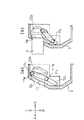
上記の蓋体開閉機構及びそれを備えた記録再生装置90は、図17(a)(b)(c)に示すように、キャビネット94の上部内壁と、MD91の挿入完了位置に配されたディスクホルダー97との間には、蓋体95が仰臥し得る程度の間隙93が設定されている。蓋体95の側面部に設けられた蓋体保持部92には、蓋体95からその長手方向に突設された第1ガイドピン95bと第2ガイドピン95cとが各々摺動する第1ガイド溝92bと第2ガイド溝92cとが形成されている。
【0012】
上記の蓋体開閉機構では、各ガイドピン95b・95cを各ガイド溝92b・95cに沿って案内することにより、蓋体95は、キャビネット94の内壁に沿うような略弧状の軌跡を描いて、その上縁部から上記間隙93に進入する。蓋体95にこのような移動軌跡を取らせることで、記録媒体を挿入する記録再生装置90の開口部94aを、記録媒体の装着状態の如何によらず蓋体95で閉状態とし、かつ記録再生装置90のキャビネット94を小型化することが可能となっている。
【0013】
【発明が解決しようとする課題】
しかしながら、上記従来の蓋体開閉機構及びそれを備えた記録再生装置90では、キャビネット94の上部内壁と、MD91の挿入完了位置に配されたディスクホルダー97との間に、蓋体95を仰臥し得る程度の間隙93が必要となるため、MD91の挿入完了位置の上部が遊びの空間なり、記録再生装置90の厚さが大きくなるという問題点を有している。
【0014】
特に、MDに関する記録再生装置は携帯用として使用されるため、極力、装置の薄型化及びコンパクト化が望まれており、この問題は重要である。
【0015】
本発明は、上記従来の問題点に鑑みなされたものであって、その目的は、記録媒体の装着時・非装着時に係わらず開口部を閉蓋状態とし、装置を薄くして小型化を図り得る蓋体開閉機構及びそれを備えた記録再生装置を提供することにある。
【0016】
【課題を解決するための手段】
本発明に係る蓋体開閉機構は、上記課題を解決するために、例えばMD等の記録媒体を内蔵したケースを挿入する開口部が筐体に形成され、開口部を開閉する蓋体が、開口部の筐体内側に備えられていると共に、筐体内に挿入され終えた挿入完了位置にあるケースを記録再生可能位置にて記録再生駆動部により記録再生するように構成された記録再生装置の蓋体開閉機構において、上記開口部の裏面側には、挿入完了位置にあるケースに対して挿入完了位置よりも開口部側かつ記録再生駆動部側に間隙が設定されており、上記開口部から挿入されるケースと当接する蓋体を、ケースの挿入による当接力によって、上記間隙により近い蓋体の辺縁部から先に間隙内に進入させる案内手段を備えていることを特徴としている。
【0017】
上記の発明によれば、例えば、開口部が形成された筐体の面を前面とし、前面から曲折する上面を考えると、上記ケースは、前面に交差するように開口部から挿入され挿入完了位置を経て記録再生位置に配されることになる。
【0018】
従来の蓋体開閉機構では、蓋体上縁部に回動軸を設け、蓋体下縁部を回動端として回動させて蓋体を間隙内に導く構成や、挿入完了位置と筐体の上面内壁との間に挿入すべく間隙を設ける構成であったので、筐体を薄型にすることが困難であった。
【0019】
しかし、本発明では、この開口部の裏面側には、挿入完了位置にあるケースに対して挿入完了位置よりも開口部側かつ記録再生駆動部側に間隙が設定されている。
【0020】
また、開口部の筐体内側に備えられた蓋体は、開蓋時には上記間隙により近い辺縁部、つまり蓋体の下辺縁部から間隙内に収容される。従って、蓋体の回動半径によって定まる従来の移動領域と比べて、蓋体の厚みで定まる本発明の移動領域はより小さくなる。また、ケースの挿入完了位置と筐体上面との間に遊びの空間を設ける必要がない。
【0021】
この結果、装置を薄くして小型化を図り得る蓋体開閉機構を提供することができる。
【0022】
本発明に係る蓋体開閉機構は、上記課題を解決するために、上記の蓋体開閉機構において、上記ケースの挿入完了位置と記録再生可能位置とが一致していると共に、ケースが挿入完了位置に到達したときに、上記蓋体の間隙への進入軌跡に沿って蓋体を逆動させ、開口部を閉状態とする付勢手段を備えていることを特徴としている。
【0023】
即ち、従来の記録再生装置では、記録再生可能位置が挿入完了位置よりも筐体の下側になるものがある。この場合、挿入完了位置と記録再生可能位置との間に、距離が必要となるので、記録再生装置の薄型化に対して障害となる。
【0024】
しかし、本発明では、挿入完了位置が記録再生可能位置に一致している。このため、挿入完了位置と記録再生可能位置との間に距離を設ける必要がない。この結果、記録再生装置を薄型化することが可能となる。
【0025】
また、本発明では、ケースが挿入完了位置に到達したときに、上記蓋体の間隙への進入軌跡に沿って蓋体を逆動させ、開口部を閉状態とする付勢手段を備えている。このため、ケースの装着・非装着に係わらず、常に開口部を閉状態として、埃や異物等の侵入から記録再生装置を充分に保護する蓋体開閉機構を提供することができる。
【0026】
本発明に係る蓋体開閉機構は、上記課題を解決するために、上記の蓋体開閉機構において、上記案内手段は、上記蓋体の長手方向両端の各側面部に、上記長手方向と平行に突出して形成された第1ガイドピン及び第2ガイドピンと、各ガイドピンを嵌入させて蓋体の移動を案内するガイド溝が形成され、対向状態で上記筐体に設けられた1対の蓋体保持部とを備え、上記ガイド溝の内、第1ガイドピンに対応する第1ガイド溝よりも第2ガイドピンに対応する第2ガイド溝が上記間隙に近い側で、上記ケースの挿入方向と略直角に形成される一方、ケースが上記間隙内に進入する際の第2ガイドピンに対する第1ガイドピンの相対的な移動が、第2ガイドピンを中心とした回動となるように、第1ガイド溝及び第2ガイド溝が形成されていることを特徴としている。
【0027】
上記の発明によれば、第1ガイドピンに対応する第1ガイド溝よりも第2ガイドピンに対応する第2ガイド溝が上記間隙に近い側にあるので、第2ガイド溝が主に蓋体の下辺縁部を案内し、第1ガイド溝が主に蓋体の上辺縁部を案内する。
【0028】
また、第2ガイド溝は、上記ケースの挿入方向と略直角に形成されているので、蓋体の長手方向両端に形成された第2ガイドピンが、それぞれの第2ガイド溝を摺動することにより、蓋体の下辺縁部は、ケースの挿入方向と略垂直に間隙内に引き込まれるように移動する。
【0029】
一方、各第1ガイド溝は、第1ガイドピンの相対的な移動が、第2ガイドピンを中心とした回動となるように形成されているので、蓋体の下辺縁部は、開口部の裏面側から上記筐体の内壁に沿う略弧状の軌跡を描くように、蓋体の下辺縁部の後から間隙内に進入する。蓋体の下縁部及び上縁部が、間隙内に上記のように案内されることにより、蓋体全体としても、略弧状の進入軌跡を描いて移動する。
【0030】
このように、蓋体の長手方向両端の各側面部にガイドピンを突設し、ガイドピンの移動を案内するガイド溝を各ガイドピンに対応付けて蓋体保持部に形成するといった簡単な構成で、蓋体の移動領域を最も小さくする略弧状の軌跡を描いて、蓋体を開口部と間隙との間で移動させることができる。
【0031】
本発明に係る蓋体開閉機構は、上記課題を解決するために、上記の蓋体開閉機構において、上記ケースの挿入開始時に、第2ガイド溝における第2ガイドピンの移動開始方向よりも筐体内側へ第1ガイドピンが移動できるように、第1ガイド溝の溝幅が、局部的に円弧状に広げられていると共に、この円弧はケースの挿入開始時に蓋体が大きく傾き、かつ挿入終了時に近づくに伴い蓋体が小さく傾くように形成されていることを特徴としている。
【0032】
上記の発明によれば、第1ガイド溝の溝幅は、ケースの挿入開始時に、第2ガイド溝における第2ガイドピンの移動開始方向よりも筐体内側へ第1ガイドピンが移動できるように、局部的に円弧状に広げられている。
【0033】
このため、ケースの挿入開始時におけるケースの蓋体への押圧によって、下方移動する蓋体の上辺縁部がこの円弧状に沿って傾斜する。従って、ケースの挿入角度に対して蓋体が直交するように閉蓋されている場合においても、ケースの挿入開始時には、蓋体を容易に傾斜してケースを抵抗なく挿入することができる。
【0034】
一方、本発明では、さらに、この円弧はケースの挿入開始時に蓋体が大きく傾き、かつ挿入終了時に近づくに伴い蓋体が小さく傾くように形成されている。
【0035】
即ち、最終的には、蓋体を間隙内に収容する必要があり、収容に際しては蓋体を立設状態にして収容したほうが、間隙幅が大きくならない。
【0036】
しかし、本発明では、上記のように第1ガイド溝の溝幅が形成されているので、間隙幅を小さくし、記録再生装置をケースの挿入方向に薄くして小型化を図り得る蓋体開閉機構を提供することができる。
【0037】
本発明に係る蓋体開閉機構は、上記課題を解決するために、上記の蓋体開閉機構において、上記蓋体を上記間隙により近い蓋体の辺縁部から先に間隙内に進入させるに際して、蓋体における長手方向の両端共を均一に進入させる進入均一化手段が設けられていることを特徴としている。
【0038】
即ち、上記蓋体を上記間隙により近い蓋体の辺縁部から先に間隙内に進入させるに際して、蓋体の一部を引っ張るように間隙内に進入させたのでは、蓋体における長手方向で偏心した状態で進入するおそれがある。
【0039】
しかし、本発明では、蓋体を上記間隙により近い蓋体の辺縁部から先に間隙内に進入させるに際して、進入均一化手段が蓋体における長手方向の両端共を均一に進入させる。
【0040】
この結果、蓋体が均一に安定して間隙に進入するので、蓋体開閉機構の品質の向上を図ることができる。
【0041】
本発明に係る記録再生装置は、上記課題を解決するために、例えばMD等の記録媒体を内蔵したケースを挿入する開口部が筐体に形成され、開口部を開閉する蓋体が、開口部の筐体内側に備えられていると共に、筐体内に挿入され終えた挿入完了位置にあるケースを記録再生可能位置にて記録再生駆動部により記録再生するように構成された記録再生装置において、上記開口部の裏面側には、挿入完了位置にあるケースに対して挿入完了位置よりも開口部側かつ記録再生駆動部側に間隙が設定されており、上記開口部から挿入されるケースと当接する蓋体を、ケースの挿入による当接力によって、上記間隙により近い蓋体の辺縁部から先に間隙内に進入させる案内手段を備えている蓋体開閉機構と、上記ケースを開口部と挿入完了位置との間で進退させると共に、挿入完了位置と記録再生可能位置との間で移動させる媒体脱着機構と、上記筐体から露出して設けられた操作部に連接され、上記ケースが記録再生可能位置にあるときに、操作者により操作された操作部の移動ストロークに対応して、上記蓋体開閉機構に係合した状態で、蓋体開閉機構に蓋体の開移動を行わせると共に、上記媒体脱着機構に係合した状態で、媒体脱着機構にケースの排出動作を行わせる係合部材とを備えていることを特徴としている。
【0042】
上記の発明によれば、蓋体を開閉する蓋体開閉機構と、ケースを記録再生装置に対して脱着する媒体脱着機構と、操作者が操作する操作部との三者が、係合部材を仲介として機構的に連動し、記録再生可能位置に配されたケースを筐体外に排出させることができる。即ち、操作部の操作ひとつで、開口部を開き、ケースを記録再生可能位置から挿入完了位置及び開口部を経て筐体外へ排出する一連の動作を、機構的な係合関係で行わせることができる。
【0043】
これにより、蓋体開閉機構の蓋体開閉動作、或いは媒体脱着機構のケース脱着動作を行わせるための専用の駆動源を別途備える必要が無い。また、駆動源の駆動力を蓋体開閉機構や媒体脱着機構に伝達するための伝達機構を別途設ける必要も無い。従って、駆動源や伝達機構を設けなくて済む分、記録再生装置の小型化もしくは薄型化、並びに軽量化を図ることができる。
【0044】
また、本発明では、蓋体が開蓋時に収容される間隙は、開口部の裏面側における、挿入完了位置にあるケースに対して挿入完了位置よりも開口部側かつ記録再生駆動部側に間隙が設定されているので、特に、記録再生装置の薄型化及び小型化を図ることができる。
【0045】
【発明の実施の形態】
〔実施の形態1〕
本発明の実施の一形態について図1ないし図7に基づいて説明すれば、以下のとおりである。
【0046】
本実施の形態で説明する記録再生装置は、MDと呼ばれる光磁気記録媒体を対象としているが、例えば、3.5インチFDやカセットテープ、或いはMOディスク等のようにハードカートリッジ(ケース)に外装された記録媒体であれば同様の蓋体開閉機構を適用することができる。
【0047】
尚、上記記録再生装置の蓋体開閉機構に関する部分を除く構成、例えば、記録媒体の装着や記録・再生に関する機構等の構成については従来と同じであるので、これらの点については、上記説明で必要となる部分に関してその都度説明するだけに留める。
【0048】
本実施の形態の蓋体開閉機構を備えた記録再生装置1は、図2に示すように、MD2よりも少し大きめの薄型の略直方体の筐体としてのキャビネット3を有しており、その前面に、MD2を挿入するための開口部3aが設けられ、その開口部3aには開閉自在の蓋体11が設けられている。
【0049】
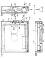
上記の記録再生装置1の内部には、図3(a)(b)(c)に示すように、挿入される上記MD2を挿入完了位置かつ記録再生位置にて保持するディスクホルダー4が設けられていると共に、その下部には上記MD2を記録再生するための記録再生駆動部5が設けられている。この記録再生駆動部5は、図示しない光ピックアップや駆動モータ等を有している。
【0050】
即ち、本実施の形態の記録再生装置1では、上述したように、MD2の挿入完了位置と記録再生位置とが同じ位置となっている。従って、MD2を挿入完了位置まで挿入すれば、その位置でMD2の記録再生が行えるようになっている。
【0051】
一方、上記の蓋体11は、蓋体開閉機構10によって、開閉するものとなっている。
【0052】
蓋体開閉機構10は、図4に示すように、蓋体11を長手方向の両翼で上下移動可能に保持する案内手段としての蓋体保持部12・12を有すると共に、蓋体11と連接された同案内手段としての蓋体開閉レバー13が回動軸13aを中心として回動可能に軸支されている構成である。
【0053】
蓋体開閉機構10を構成する各部材についてさらに詳細に述べる。尚、図2及び図4に示された矢印A〜H方向は、次のように定義される。上記開口部3aが形成された記録再生装置1の面を前面かつ正面として、矢印A方向を記録再生装置1の前方、矢印B方向を記録再生装置1の後方、矢印C方向を記録再生装置1の上方、矢印D方向を記録再生装置1の下方、矢印A方向を記録再生装置1の後方に向かって左側方、矢印B方向を記録再生装置1の後方に向かって右側方、矢印H方向を上記F方向に向かって時計回り、矢印G方向を上記F方向に向かって反時計回りとする。また、A−B方向、C−D方向、E−F方向は、互いに直交関係にある。但し、他の図面においては、上記A〜F方向における各方向の整合性は必ずしもない。
【0054】
先ず、図4に示すように、蓋体11には、矢印A方向側の面、即ち前面に、上下に延びかつ矢印A方向に突出した二条の凸部11a・11aが蓋体11の面に沿って形成されている。また、蓋体11における矢印E−F方向の両側部からは、矢印E−F方向の両方向に突出する第1ガイドピン11b・11bと第2ガイドピン11c・11cとがそれぞれ形成されている。
【0055】
各蓋体保持部12・12には、上下方向に直線状に穿設されかつ上記第1ガイドピン11b・11bが摺動可能に挿通する第1ガイド溝12b・12bと、第1ガイド溝12b・12bの下端部12b1 ・12b1 の下方位置に少し離れて、これら第1ガイド溝12b・12bに対して下端が少し矢印A方向へ傾斜するように穿設された第2ガイド溝12c・12cとが形成されている。これら第2ガイド溝12c・12cには、第2ガイドピン11c・11cが摺動可能に挿入されている。
【0056】
尚、これら第2ガイド溝12c・12cは、必ずしも傾斜させる必要はなく、立設状態に形成することも可能である。また、上記の各ガイド溝12b・12c及び各ガイドピン11b・11cも、本発明の案内手段を構成している。
【0057】
一方、図5(b)に示すように、開口部3aの裏面側には、挿入完了位置にあるMD2に対して挿入完了位置よりも開口部3a側かつ記録再生駆動部5側に間隙6が設定されている。そして、上記の蓋体11は、後述するように、外部から挿入されるMD2と当接することにより、このMD2の挿入による当接力によって、間隙6により近い蓋体11の下辺縁部11dから先に間隙6内に進入するものとなっている。
【0058】
一方、図4に示すように、上記蓋体開閉レバー13は、略くの字状に形成され、その中央に上記の回動軸13aを有している。また、蓋体開閉レバー13の矢印F方向の端部には駆動部13cが形成される一方、矢印E方向の端部には、蓋体11に係合する蓋体係合部13bが設けられている。この蓋体開閉レバー13は、図示しない付勢手段としてのバネやスプリング等の弾性部材にて反時計方向に付勢されている。この結果、蓋体11は絶えず上方移動するように付勢されている。
【0059】
上記の蓋体開閉機構10におけるMD2を装着するときの蓋体11の開閉動作について、以下に説明する。
【0060】
先ず、MD2が記録再生装置1に未装着のときは、図1(a)に示すように、蓋体11はその上下縁部が開口部3aに密着状態となり、蓋体11における全閉状態となっている。この状態から、MD2を装着すべく、MD2を開口部3aに向けて矢印B方向に挿入する。
【0061】
次いで、図1(b)に示すように、MD2の矢印B方向先端部を蓋体11の凸部11aに当接させて、蓋体11を矢印B方向に押圧すると、凸部11aに形成されている傾斜により、第1ガイドピン11b及び第2ガイドピン11cが、それぞれ第1ガイド溝12b及び第2ガイド溝12cに沿って案内され、下方移動する。
【0062】
即ち、上記蓋体11における凸部11aは、傾斜状態に形成されているので、MD2の凸部11aへの当接及び押圧によって、下方への分力が作用し、蓋体11に下方への移動力が働く。このため、MD2をさらに挿入移動させると、蓋体11が第1ガイドピン11b及び第2ガイドピン11cを介して第1ガイド溝12b及び第2ガイド溝12cに沿って下方移動することになる。この結果、凸部11aの傾斜は、矢印A−B方向に対して緩い程、下方移動し易くなる。
【0063】
また、本実施の形態では、第1ガイド溝12bが略垂直方向に穿設されているのに対して、第2ガイド溝12cはこれよりも少し傾斜を有して穿設されている。さらに、蓋体11は蓋体開閉レバー13を介して図示しないバネ等にて上方向に付勢されている。このため、蓋体11の下方への移動に際しては、下方に向かうに従って、逐次傾斜角度が緩くなるように移動するようになっている。
【0064】
次いで、図1(c)に示すように、MD2をさらに挿入すると、MD2と蓋体11の凸部11aとの摺動により、やがて、MD2は蓋体11の上辺縁部11eを摺動しながら通過する。このとき、上記第1ガイドピン11b及び第2ガイドピン11cは、第1ガイド溝12b及び第2ガイド溝12cの各最下端位置にまで到達している。
【0065】
次いで、図1(d)に示すように、MD2を矢印B方向にさらに押圧して、MD2の後端が開口部3aを越えると、図示しないMD装着機構により、MD2がディスクホルダー4の奥へ引き込まれる。そして、MD2と蓋体11の上辺縁部11eとの係合が外れると、蓋体11は前記弾性部材により、第1ガイドピン11b及び第2ガイドピン11cの第1ガイド溝12b及び第2ガイド溝12cに沿う案内移動により、上方移動し、元の閉蓋状態に戻る。そして、同図(d)に示す位置にてMD2はディスクホルダー4内に完全に収納され、挿入完了位置となると共に、その位置が記録再生可能位置となる。これにより、図5(a)(b)(c)にも示すように、MD2の装着が完了する。
【0066】
このように蓋体11は、MD2の非装着状態のみならず、装着状態においても全閉可能とされているので、MD2の装着又は非装着に係わらず埃や異物等の侵入を防止できる。
【0067】
次に、MD2を取り出す場合の蓋体開閉機構10の動作を、図5(a)(b)(c)に基づいて説明する。
【0068】
先ず、MD2が装着されているときは、図5(a)に示すように、蓋体11は全閉状態とされている。この状態から、ユーザが図示しないイジェクト操作手段を作動させると、蓋体開閉レバー13の駆動部13cが図示しないイジェクト機構により反時計方向の付勢を受けて、図示しないバネの付勢力に抗して、回動軸13aを中心にして反時計方向に回動し始める。
【0069】
その結果、蓋体係合部13bが反時計方向に回動し、これに伴って、蓋体11は下方移動し、蓋体11が全開状態となる。
【0070】
上記全開状態でさらに図示しないイジェクト操作手段を操作すると、イジェクト機構は、MD2を矢印D方向に排出させるので、MD2の一部が開口部3aよりも外部に突出する。
【0071】
次いで、ユーザがこのMD2を掴んで、開口部3aより取り出せば、MD2の下面による蓋体11の拘束状態が解除されるので、図示しないバネにより蓋体開閉レバー13に加えられた時計方向の付勢力により、蓋体11が再び開口部3aを全閉状態とする。
【0072】
つまり、記録再生可能位置かつ挿入完了位置にあるMD2を排出させるときに、ユーザによるイジェクト操作に機構的に連動させて、蓋体11を開放してMD2の取り出しを可能とし、さらに、MD2を完全に取り出せば、蓋体11を全閉状態とすることができる。尚、イジェクト機構及びMD2の装着機構と蓋体11とを連動させる機構については、後述の実施の形態2で詳しく説明する。
【0073】
このように、本実施の形態の蓋体開閉機構10を有する記録再生装置1では、MD2は、前面に交差するように開口部3aから挿入され挿入完了位置かつ記録再生位置に配されることになる。
【0074】
ところで、従来の蓋体開閉機構では、蓋体上縁部に回動軸を設け、蓋体下縁部を回動端として回動させて蓋体を間隙内に導く構成や、挿入完了位置とキャビネット3の上面内壁との間に挿入すべく間隙を設ける構成であったので、キャビネット3を薄型にすることが困難であった。
【0075】
しかし、本実施の形態では、開口部3aの裏面側には、挿入完了位置にあるMD2に対して挿入完了位置よりも開口部3a側かつ記録再生駆動部5側に間隙6が設定されている。
【0076】
また、開口部3aのキャビネット3内側に備えられた蓋体11は、開蓋時には上記間隙6により近い辺縁部、つまり蓋体11の下辺縁部11dから間隙6内に収容される。従って、蓋体11の回動半径によって定まる従来の移動領域と比べて、蓋体11の厚みで定まる本実施の形態の移動領域はより小さくなる。また、MD2の挿入完了位置とキャビネット3の上面との間に遊びの空間を設ける必要がない。
【0077】
この結果、記録再生装置1を薄くして小型化を図り得る蓋体開閉機構10を提供することができる。
【0078】
一方、従来の記録再生装置では、例えば、記録再生可能位置が挿入完了位置よりもキャビネット3の下側になる構成のものがある。この場合、挿入完了位置と記録再生可能位置との間に、距離が必要となるので、記録再生装置1の薄型化に対して障害となる。
【0079】
しかし、本実施の形態では、挿入完了位置が記録再生可能位置に一致している。このため、挿入完了位置と記録再生可能位置との間に距離を設ける必要がない。この結果、記録再生装置1を薄型化することが可能となる。
【0080】
また、本実施の形態では、MD2が挿入完了位置に到達したときに、蓋体11の間隙6への進入軌跡に沿って蓋体11を逆動させ、開口部3aを閉状態とする蓋体開閉レバー13を備えている。このため、MD2の装着又は非装着に係わらず、常に開口部3aを閉状態として、埃や異物等の侵入から記録再生装置1を充分に保護する蓋体開閉機構10を提供することができる。
【0081】
また、本実施の形態の蓋体開閉機構10では、第1ガイドピン11bに対応する第1ガイド溝12bよりも第2ガイドピン11cに対応する第2ガイド溝12cが間隙6に近い側にあるので、第2ガイド溝12cが主に蓋体11の下辺縁部11dを案内し、第1ガイド溝12bが主に蓋体11の上辺縁部11eを案内する。
【0082】
また、第2ガイド溝12cは、MD2の挿入方向と略直角に形成されているので、蓋体11の長手方向両端に形成された第2ガイドピン11c・11cが、それぞれの第2ガイド溝12c・12cを摺動することにより、蓋体11の下辺縁部11dは、MD2の挿入方向と略垂直に間隙6内に引き込まれるように移動する。
【0083】
一方、各第1ガイド溝12b・12bは、第1ガイドピン11b・11bの相対的な移動が、第2ガイドピン11c・11cを中心とした回動となるように形成されているので、蓋体11の下辺縁部11dは、開口部3aの裏面側からキャビネット3の内壁に沿う略弧状の軌跡を描くように、蓋体11の下辺縁部11dの後から間隙6内に進入する。そして、蓋体11の下辺縁部11d及び上辺縁部11eが、間隙6内に上記のように案内されることにより、蓋体11全体としても、略弧状の進入軌跡を描いて移動する。
【0084】
このように、蓋体11の長手方向両端の各側面部に第1ガイドピン11b・11b及び第2ガイドピン11c・11cを突設し、第1ガイドピン11b・11b及び第2ガイドピン11c・11cの移動を案内する第1ガイド溝12b・12b及び第2ガイド溝12c・12cを各第1ガイドピン11b・11b及び第2ガイドピン11c・11cに対応付けて蓋体保持部12・12に形成するといった簡単な構成で、蓋体11の移動領域を最も小さくする略弧状の軌跡を描いて、蓋体11を開口部3aと間隙6との間で移動させることができる。
【0085】
また、本実施の形態では、MD2の挿入方向と略垂直に間隙6内に引き込まれるように蓋体11が移動するに際して、この蓋体11の移動は、開口部3aの裏側において、キャビネット3の挿入側の内壁に沿った平行移動とすることが可能である。
【0086】
これによって、蓋体11の移動時における占有空間を低減することができるので、記録再生装置1の小型化及び薄型化が可能となる。
【0087】
また、本実施の形態では、蓋体11の凸部11a・11aにおける傾斜を大きくとることが可能である。
【0088】
これによって、MD2の挿入時における蓋体11への当接及び押圧に際して、蓋体11の下方移動を容易にすることができる。
【0089】
尚、本発明は、上記の実施の形態に限定されるものではなく、本発明の範囲内で種々の変更が可能である。例えば、上記実施の形態では、第1ガイド溝12bは、直線状に形成されていたが、特にこれに限定するものではなく、例えば、図6(a)(b)に示すように、矢印B方向側に湾曲凹部となる第1ガイド溝22bを形成することが可能である。
【0090】
即ち、本実施の形態では、MD2を記録再生装置1に装着する際に、その挿入力で蓋体11を下方に移動させるべく、蓋体11に凸部11aを設け、その傾斜を大きくすることによって容易に蓋体11を下方移動し得るものとなっている。
【0091】
しかし、凸部11aの傾斜を大きくとるための空間が無い場合やデザイン上の制約がある場合もある。
【0092】
このようなときに、上述した第1ガイド溝22bを穿設することによって、容易に蓋体11を下方移動させることができる。
【0093】
即ち、この第1ガイド溝22bでは、MD2が蓋体11を押圧すると、蓋体11が第2ガイドピン11cを中心として傾斜しながら下方移動する。このため、MD2は容易に進入することが可能であり、蓋体11の下方移動も容易である。
【0094】
このように、本実施の形態では、第1ガイド溝22bの溝幅は、MD2の挿入開始時に、第2ガイド溝12cにおける第2ガイドピン11cの移動開始方向よりもキャビネット3内側へ第1ガイドピン11bが移動できるように、局部的に円弧状に広げることが可能である。
【0095】
これによって、MD2ケースの挿入開始時におけるMD2の蓋体11への押圧によって、下方移動する蓋体11の上辺縁部11eがこの円弧状に沿って傾斜する。従って、MD2の挿入角度に対して蓋体11が直交するように閉蓋されている場合においても、MD2の挿入開始時には、蓋体11を容易に傾斜してMD2を抵抗なく挿入することができる。
【0096】
一方、本実施の形態では、さらに、この円弧はMD2の挿入開始時に蓋体11が大きく傾き、かつ挿入終了時に近づくに伴い蓋体11が小さく傾くように形成されている。
【0097】
即ち、最終的には、蓋体11を間隙6内に収容する必要があり、収容に際しては蓋体11を立設状態にして収容した方が、間隙6の幅が大きくならない。
【0098】
この点、本実施の形態では、上記のように第1ガイド溝22bの溝幅が形成されているので、間隙幅を小さくし、記録再生装置1をMD2の挿入方向に薄くして小型化を図り得る蓋体開閉機構10を提供することができる。
【0099】
ところで、本実施の形態では、蓋体開閉レバー13は、一つのレバーにて構成されていると共に、蓋体11との蓋体係合部13bが一点連結となっているので、蓋体11の上下移動の安定性に欠けるおそれがある。そこで、例えば、図7に示すように、蓋体51の開閉移動時の左右バランスを良好に保つために、蓋体開閉レバー53に交差する蓋体同期レバー52を設け、蓋体51を二点支持することが可能である。尚、この構成については、後述する実施の形態3にて詳細に説明する。
【0100】
〔実施の形態2〕
本発明の実施の他の形態について図8ないし図10に基づいて説明すれば、以下のとおりである。尚、説明の便宜上、前記実施の形態1の図面に示した部材と同一の機能を有する部材には、同一の符号を付記して、その説明を省略する。
【0101】
本実施の形態では、記録再生装置に装着されたMDを排出させるために、操作者が操作するイジェクト機構と、実施の形態1で説明した蓋体開閉機構とを連動させる機構について説明する。
【0102】
先ず、前記図2に示すように、本実施の形態の記録再生装置1における開口部3aが形成されたキャビネット3の側面には、操作部としてのイジェクトつまみ31が設けられている。
【0103】
そして、操作者がこのイジェクトつまみ31を回動操作することにより、図8(a)(b)(c)に示すように、イジェクト機構30にて、蓋体11が開蓋状態になると共に、MD2を開口部3aから外に排出することができるものとなっている。
【0104】
上記のイジェクト機構30は、同図(a)(b)(c)に示すように、上記のイジェクトつまみ31と、キャビネット3の側面の裏側に固定されたイジェクトフレーム32と、イジェクトつまみ31の回動駆動力を蓋体開閉レバー13に伝達するための係合部材としての連結レバー33と、イジェクトつまみ31の回動によりMD2を記録再生位置から排出移動させるためのディスクイジェクトレバー34等を有している。
【0105】
上記イジェクトフレーム32には、キャビネット3の側面の矢印C−D方向の略中央にイジェクトつまみ31が回動支点31aを中心に回動自在に取り付けられる一方、同図(b)に示すように、キャビネット3の側面において、矢印B方向側に、つまりキャビネット3の底面近傍に、上記の連結レバー33が回動支点33aを中心に矢印G−H方向に回動自在に取り付けられている。
【0106】
また、上記のイジェクトつまみ31には、上部における矢印C方向の外周近傍位置に作用ピン31bが設けられると共に、上部における矢印D方向の外周近傍位置に作用ピン31cが設けられている。
【0107】
さらに、イジェクトつまみ31は、図示しないバネによって、矢印H方向に付勢されている。
【0108】
一方、ディスクイジェクトレバー34は、記録再生駆動部5に矢印C−D方向に移動自在に設けられ、その矢印C−D方向の略中央位置に作用部34aを有している。
【0109】
また、ディスクイジェクトレバー34は、前記図示しないMD装着機構と連動すると共に、挿入完了位置におけるMD2に係合している。このMD装着機構は、イジェクトつまみ31の作用ピン31bがこのディスクイジェクトレバー34の作用部34aに係合してディスクイジェクトレバー34を矢印D方向に移動させることにより、記録再生位置にあるMD2を矢印D方向に移動させ、記録再生装置1の外部に排出するものとなっている。
【0110】
一方、上記の連結レバー33は、矢印C−D方向に略くの字状に形成されており、その略中央に上記の回動支点33aが設けられている。この連結レバー33の矢印C方向の端部には、立上げ部33bが設けられており、その立上げ部33bの上端には矢印C方向になだらかに折曲された折曲部33cが形成されている。
【0111】
そして、この折曲部33cは、上記イジェクトつまみ31の作用ピン31cに係合しており、イジェクトつまみ31を操作しない状態では、作用ピン31cは折曲部33cに当接している。
【0112】
また、連結レバー33の矢印D方向の端部には、作用部33dが設けられており、前記蓋体開閉レバー13の駆動部13cに係合するようになっている。
【0113】
一方、上記蓋体開閉レバー13は、図8(c)に示すように、キャビネット3に固定された固定フレーム14に回動軸13aにて軸支されている。また、蓋体開閉レバー13は、図示しない別のバネによって、矢印H方向に付勢されている。さらに、前記実施の形態1で述べたように、蓋体開閉レバー13の他端は蓋体係合部13bにて蓋体11と係合している。このため、蓋体11は絶えず閉蓋状態を保持するようになっている。
【0114】
上記構成のイジェクト機構30の動作について、以下に説明する。
【0115】
図8(a)(b)(c)に示すように、MD2がディスクホルダー4内の記録再生位置にあるときには、蓋体11は閉蓋状態となっている。この状態においては、蓋体開閉レバー13はバネにて矢印H方向に付勢されているので、上述したように、閉蓋状態を保持するようになっている。従って、この状態では、くの字状の蓋体開閉レバー13は蓋体係合部13bが上部に位置する一方、駆動部13cがキャビネット3の略底面近傍の下端位置となっている。
【0116】
この駆動部13cには、連結レバー33の作用部33dが係合している。このため、くの字状の連結レバー33の他端にある立上げ部33bの下端とキャビネット3の底面との間には、クリアランスが形成されている。また、立上げ部33bの上端の折曲部33cは、イジェクトつまみ31の作用ピン31cに当接している。
【0117】
ここで、イジェクトつまみ31も矢印H方向に付勢されているので、イジェクトつまみ31の作用ピン31cの連結レバー33の折曲部33cへの当接においては、連結レバー33の折曲部33cは、自然状態では押し下がらないものとなっている。
【0118】
この状態から、イジェクトつまみ31を矢印G方向に回動させると、連結レバー33の折曲部33cに当接している作用ピン31cが折曲部33cを押し下げる。このため、連結レバー33は回動支点33aを中心にして矢印H方向に回動し、連結レバー33の他端部の作用部33dが持ち上がる。その結果、連結レバー33におけるこの作用部33dを介して、蓋体開閉レバー13の駆動部13cが矢印C方向に持ち上がる。この結果、蓋体開閉レバー13が回動軸13aを中心として矢印G方向に回動するので、蓋体係合部13bを介して蓋体11が矢印D方向に移動して開蓋動作を始める。
【0119】
一方、このとき、イジェクトつまみ31の外周近傍に設けられた作用ピン31bも矢印G方向に回動し、やがて、図9(a)(b)(c)に示すように、作用ピン31bがディスクイジェクトレバー34に設けられた作用部34aに当接する。
【0120】
尚、この位置までの回動は、弱い力で容易に行うことができるものとなっている。そして、同図(a)(b)(c)の状態では、イジェクトつまみ31の作用ピン31cは、未だ、折曲部33cに係合していると共に、折曲部33cを一杯に押し下げた状態となっているので、蓋体11は、連結レバー33の作用部33d、蓋体開閉レバー13の駆動部13c及び蓋体係合部13bを介して矢印D方向一杯に下降移動して開蓋状態を維持している。
【0121】
次いで、この状態から、さらにイジェクトつまみ31を先程よりもやや少し力をかけて回動させると、イジェクトつまみ31の作用ピン31bとディスクイジェクトレバー34の作用部34aとの係合により、ディスクイジェクトレバー34に矢印D方向の力が作用し、これによって、MD装着機構のディスクイジェクトレバー34の作用部34aを矢印D方向に移動させて、記録再生位置にあるMD2を装着解除する。これによって、MD2が矢印D方向に移動する。
【0122】
一方、このとき、連結レバー33の折曲部33cに係合していたイジェクトつまみ31の作用ピン31cは、イジェクトつまみ31の瞬時の回動により、図10(a)(b)(c)に示すように、折曲部33cとの係合が外れると同時に、連結レバー33の立上げ部33bの根元まで移動する。このため、連結レバー33の立上げ部33bの下端部は、キャビネット3の底面近くの位置を維持する。
【0123】
このため、連結レバー33は回動変化しないので、蓋体11が開蓋状態を維持する。
【0124】
この結果、MD2は、蓋体11に阻止されることなく、キャビネット3外に突出され、その後、操作者がその一端を掴んで記録再生装置1の外へ排出することができる。
【0125】
このように、本実施の形態の記録再生装置1では、蓋体11を開閉する蓋体開閉機構10と、MD2を記録再生装置1に対して脱着する媒体脱着機構と、操作者が操作するイジェクトつまみ31との三者が、連結レバー33を仲介として機構的に連動し、記録再生可能位置に配されたMD2をキャビネット3外に排出させることができる。即ち、イジェクトつまみ31の操作一つで、開口部3aを開き、MD2を記録再生可能位置から開口部3aを経てキャビネット3外へ排出する一連の動作を、機構的な係合関係で行わせることができる。
【0126】
これにより、蓋体開閉機構10の蓋体開閉動作、或いは媒体脱着機構のMD2着脱動作を行わせるための専用の駆動源を別途備える必要が無い。また、駆動源の駆動力を蓋体開閉機構10や媒体脱着機構に伝達するための伝達機構を別途設ける必要も無い。従って、駆動源や伝達機構を設けなくて済む分、記録再生装置1の小型化若しくは薄型化、並びに軽量化を図ることができる。
【0127】
〔実施の形態3〕
本発明の実施の他の形態について図11ないし図14に基づいて説明すれば、以下のとおりである。尚、説明の便宜上、前記実施の形態1及び実施の形態2の図面に示した部材と同一の機能を有する部材には、同一の符号を付記して、その説明を省略する。
【0128】
本実施の形態では、実施の形態1で少し述べた蓋体11を二点支持して上下移動させる蓋体同期安定機構と操作者が操作するイジェクト機構とを連動させる機構について説明する。
【0129】
本実施の形態の蓋体開閉機構50は、図11に示すように、前記実施の形態1で示した蓋体11に対して下辺縁部11dに設けた蓋体係合部51e・51eが矢印E−F方向の2箇所に設けられた蓋体51を有している。上記の蓋体係合部51e・51eには、それぞれ蓋体係合孔51a・51aが穿設されている。尚、蓋体51のその他の構造は、前記蓋体11と同じである。従って、蓋体51の長手方向の両翼で蓋体51を上下移動可能に保持する蓋体保持部12・12も前記実施の形態1で示したものと同じ構造である。
【0130】
一方、上記蓋体51の下方には、略くの字状に形成された蓋体開閉レバー53が設けられると共に、この蓋体開閉レバー53に交差する蓋体同期レバー52が略くの字状に形成されて上記蓋体開閉レバー53と左右対称形状に設けられている。
【0131】
上記蓋体開閉レバー53の中心には回動軸53cが矢印B方向に設けられる一方、蓋体同期レバー52の中心には貫通孔52cが穿設されている。そして、上記の蓋体開閉レバー53の回動軸53cはこの貫通孔52cに貫通されており、これによって、蓋体開閉レバー53及び蓋体同期レバー52は、回動軸53cを中心として互いに回動自在となっている。
【0132】
また、蓋体開閉レバー53の上端部及び下端部には作用ピン53a・53bがそれぞれ設けられる一方、蓋体同期レバー52の上端部及び下端部にも作用ピン52a・52bがそれぞれ設けられている。
【0133】
上記の蓋体開閉レバー53及び蓋体同期レバー52の矢印B方向側には固定フレーム54と同期連結レバー55とが順に設けられている。
【0134】
上記の固定フレーム54は、前記キャビネット3に固定されている。また、固定フレーム54には、下部に2ヵ所の横溝54b・54bが穿設されると共に、中央に縦溝54cが穿設されている。
【0135】
一方、同期連結レバー55には、2つの横溝55d・55dが穿設されており、上記固定フレーム54に形成されたピン54d・ピン54dが通され、これによって、同期連結レバー55は、矢印E−F方向に移動自在となっている。また、同期連結レバー55に中央位置には、斜め溝55cが穿設されており、前記蓋体開閉レバー53の回動軸53cが上記固定フレーム54の縦溝54cを通してこの斜め溝55cに通されるようになっている。
【0136】
また、前記蓋体開閉レバー53の作用ピン53a・53b及び蓋体同期レバー52の作用ピン52a・52bは、それぞれ固定フレーム54の横溝54b・54b及び蓋体51における蓋体係合部51e・51eの蓋体係合孔51a・51aに通されている。
【0137】
この結果、同期連結レバー55が矢印F方向に移動すると、同期連結レバー55の斜め溝55cに通された蓋体開閉レバー53の回動軸53cが斜め溝55cに案内されて上方へ移動する。これによって、蓋体開閉レバー53及び同期連結レバー55の上端がそれぞれ持ち上がるので、作用ピン52a・52bが上方移動し、蓋体51を持ち上げる。このため、下方にあった蓋体51が上方移動して開口部3aを閉じる。
【0138】
逆に、同期連結レバー55を矢印E方向に移動すると、全く逆の動作で、同期連結レバー55の斜め溝55cに通された蓋体開閉レバー53の回動軸53cが斜め溝55cに案内されて下方へ移動する。この結果、蓋体開閉レバー53及び同期連結レバー55の上端がそれぞれ持ち下がるので、作用ピン52a・52bが下方移動し、蓋体51を持ち下げる。このため、上方にあった蓋体51が下方移動して開口部3aを開ける。
【0139】
尚、上記の同期連結レバー55が矢印E−F方向に移動するのは、同期連結レバー55の矢印F方向の端部に形成された駆動部55aに、以下に述べるイジェクト機構60が作用するためである。
【0140】
上記のイジェクト機構60について説明する。
【0141】
本実施の形態のイジェクト機構60は、図12(a)(b)(c)に示すように、イジェクトつまみ61と、キャビネット3の側面の裏側に固定されたイジェクトフレーム62と、このイジェクトフレーム62の内側でイジェクトフレーム62に沿って移動自在にスライドするスライドレバー65と、イジェクトつまみ61の回動駆動力を上記スライドレバー65を介して蓋体開閉レバー53に伝達するための連結レバー63と、イジェクトつまみ61の回動によりMD2を記録再生位置から排出移動させるためのディスクイジェクトレバー64等を有している。
【0142】
上記イジェクトフレーム62には、キャビネット3の側面の矢印C−D方向の略中央にイジェクトつまみ61が回動支点61aを中心に回動自在に取り付けられる一方、キャビネット3の側面の矢印D方向側に上記の連結レバー63が回動支点63aを中心に回動自在に取り付けられている。
【0143】
また、イジェクトフレーム62における矢印D方向の端部の下側には、上記の連結レバー63が、回動支点63aを中心として同図(a)において矢印G−H方向に回動自在に設けられている。
【0144】
また、上記のイジェクトつまみ61には、上部におけるやや矢印C方向の外周近傍位置に作用ピン61bが設けられている。
【0145】
上記のスライドレバー65には、矢印C−D方向の両側に横溝65a・65aが穿設されており、これら横溝65a・65aに、イジェクトフレーム62に形成された作用ピン62a・62aが通されることによって、スライドレバー65は、矢印C−D方向に移動自在となっている。
【0146】
また、スライドレバー65は、矢印C−D方向の略中央位置の上側において、内側つまり矢印A方向に突出する駆動部65bを有している。
【0147】
さらに、スライドレバー65は、下側における矢印D方向の端部に、外側になだらかに折曲する折曲部65cを有している。
【0148】
この折曲部65cは、スライドレバー65の矢印D方向への移動によって、連結レバー63に上側に突出して設けられた駆動ピン63cに押圧係合することにより、上記連結レバー63を回動支点63aを中心として、同図(a)において矢印H方向に回動するようになっている。
【0149】
また、このとき、連結レバー63の矢印D方向の端部に設けられた作用ピン63bが、前記同期連結レバー55の駆動部55aを押圧係合するようになっており、これによって、蓋体51の開蓋を可能とするものとなっている。
【0150】
さらに、連結レバー63は、後述するように、同期連結レバー55が閉蓋状態を保つべく、図示しない別のバネによって、矢印B方向に付勢されているので、この連結レバー63は、通常は、キャビネット3の側面に接触する状態を維持するものとなっている。
【0151】
一方、上記のディスクイジェクトレバー64は、記録再生駆動部5において矢印C−D方向に移動自在に設けられ、その矢印C−D方向の略中央位置に作用部64aを有している。
【0152】
そして、ディスクイジェクトレバー64は、前記図示しないMD装着機構と連動すると共に、挿入完了位置におけるMD2に係合しており、このMD装着機構は、スライドレバー65の駆動部65bがこのディスクイジェクトレバー64の作用部64aに係合して矢印D方向に移動することにより、記録再生位置にあるMD2を矢印D方向に移動させ、記録再生装置1の外部に排出するものとなっている。
【0153】
一方、図12(c)に示すように、上記蓋体開閉レバー53及び蓋体同期レバー52は、回動軸53cにて回動自在となっていると共に、同期連結レバー55は矢印B方向に図示しないバネによって付勢されている。従って、蓋体51は閉蓋状態となるように付勢されている。
【0154】
上記構成のイジェクト機構60の動作について、以下に説明する。
【0155】
図12(a)(b)(c)に示すように、MD2がディスクホルダー4内の記録再生位置にあるときには、蓋体51は閉蓋状態となっている。この状態においては、同期連結レバー55はバネにて矢印B方向に付勢されており、蓋体開閉レバー53及び同期連結レバー55は、回動軸53cが同期連結レバー55の前記斜め溝55cに案内されて上端に位置することにより、蓋体係合部51e・51eが上部位置を保持している。
【0156】
また、同期連結レバー55の駆動部55aは、イジェクト機構60における連結レバー63の作用ピン63bを押圧して係合している。このため、連結レバー63は、回動してキャビネット3の近傍に位置している。
【0157】
また、このとき、スライドレバー65の折曲部65cは、連結レバー63の駆動ピン63cに当接する一方、スライドレバー65の駆動部65bには、イジェクトつまみ61の作用ピン61bが当接している。
【0158】
また、スライドレバー65は、図示しないバネによって、矢印C方向に付勢されている。このため、イジェクトつまみ61も、スライドレバー65の駆動部65b及びイジェクトつまみ61の作用ピン61bを介して矢印H方向に付勢されている。
【0159】
この状態から、イジェクトつまみ61を矢印G方向に回動させると、イジェクトつまみ61の作用ピン61bがスライドレバー65の駆動部65bを矢印D方向に押圧する。これによって、やがて、図13(a)(b)(c)に示すように、スライドレバー65の駆動部65bは、ディスクイジェクトレバー64の作用部64aに当接する。
【0160】
一方、このときまでに、スライドレバー65の折曲部65cは、連結レバー63の駆動ピン63cを押圧する。
【0161】
このため、図13(a)(b)(c)に示すように、連結レバー63は、回動支点63aを中心として矢印H方向に回動する。このとき、連結レバー63の駆動ピン63cは回動支点63aの近くにあるため、この駆動ピン63cを折曲部65cにて押圧すると、連結レバー63の端部の作用ピン63bでは、大きな回動ストロークを発生する。
【0162】
この結果、連結レバー63の作用ピン63bに係合している同期連結レバー55における駆動部55aを介して、同期連結レバー55が矢印A方向に移動する。これによって、図11に示す蓋体開閉レバー53の回動軸53cが、矢印E方向に移動する同期連結レバー55の斜め溝55cに案内されて、下方移動する。
【0163】
この結果、蓋体開閉レバー53の作用ピン53a及び作用ピン52aが下方移動し、これに伴って、これら作用ピン53a・52aが係合する蓋体51の蓋体係合部51e・51eが下方移動するので、図13(a)(b)(c)に示すように、蓋体51が開蓋状態となる。
【0164】
次いで、この状態から、さらにイジェクトつまみ61を先程よりもやや少し力をかけて回動させると、イジェクトつまみ61の作用ピン61bを介してスライドレバー65の駆動部65bがディスクイジェクトレバー64の作用部64aを押圧するので、ディスクイジェクトレバー64に矢印D方向の力が作用し、これによって、MD装着機構のディスクイジェクトレバー64の作用部64aを矢印D方向に移動させて、記録再生位置にあるMD2を装着解除する。これによって、MD2が矢印D方向に移動する。
【0165】
一方、このとき、連結レバー63の駆動ピン63cに係合していたスライドレバー65の折曲部65cは、駆動ピン63cに当接した状態でなお押圧を続けるので、連結レバー63は、図14(a)(b)(c)に示すように、矢印H方向への回動力を与え続ける。このため、連結レバー63の作用ピン63bは、同期連結レバー55の駆動部55aを押圧し続けるので、蓋体開閉レバー53及び蓋体同期レバー52は、図12に示す斜め溝55cを介して回動軸53cが下方位置状態を保ち、その結果、蓋体51の開蓋状態を維持する。
【0166】
この結果、MD2は、蓋体51に阻止されることなく、キャビネット3外に突出され、その後、操作者がその一端を掴んで記録再生装置1の外へ排出することができる。
【0167】
このように、蓋体51を間隙6により近い下辺縁部11dから先に間隙6内に進入させるに際して、蓋体51の一部を引っ張るように間隙6内に進入させたのでは、蓋体51における長手方向で偏心した状態で進入するおそれがある。
【0168】
しかし、本実施の形態の蓋体開閉機構50では、蓋体51を間隙6により近い下辺縁部11dから先に間隙6内に進入させるに際して、進入均一化手段としての蓋体開閉レバー53及び蓋体同期レバー52が蓋体における長手方向の両端共を均一に進入させる。
【0169】
この結果、蓋体51蓋体が均一に安定して間隙6に進入するので、蓋体開閉機構50の品質の向上を図ることができる。
【0170】
【発明の効果】
本発明に係る蓋体開閉機構は、以上のように、開口部の裏面側には、挿入完了位置にあるケースに対して挿入完了位置よりも開口部側かつ記録再生駆動部側に間隙が設定されており、上記開口部から挿入されるケースと当接する蓋体を、ケースの挿入による当接力によって、上記間隙により近い蓋体の辺縁部から先に間隙内に進入させる案内手段を備えているものである。
【0171】
それゆえ、蓋体の回動半径によって定まる従来の移動領域と比べて、蓋体の厚みで定まる本発明の移動領域はより小さくなる。また、ケースの挿入完了位置と筐体上面との間に遊びの空間を設ける必要がない。
【0172】
この結果、装置を薄くして小型化を図り得る蓋体開閉機構を提供することができるという効果を奏する。
【0173】
本発明に係る蓋体開閉機構は、以上のように、上記の蓋体開閉機構において、上記ケースの挿入完了位置と記録再生可能位置とが一致していると共に、ケースが挿入完了位置に到達したときに、上記蓋体の間隙への進入軌跡に沿って蓋体を逆動させ、開口部を閉状態とする付勢手段を備えているものである。
【0174】
それゆえ、挿入完了位置が記録再生可能位置に一致しているので、挿入完了位置と記録再生可能位置との間に距離を設ける必要がない。この結果、記録再生装置を薄型化することが可能となる。
【0175】
また、本発明では、ケースが挿入完了位置に到達したときに、上記蓋体の間隙への進入軌跡に沿って蓋体を逆動させ、開口部を閉状態とする付勢手段を備えている。このため、ケースの装着・非装着に係わらず、常に開口部を閉状態として、埃や異物等の侵入から記録再生装置を充分に保護する蓋体開閉機構を提供することができるという効果を奏する。
【0176】
本発明に係る蓋体開閉機構は、以上のように、上記の蓋体開閉機構において、上記案内手段は、上記蓋体の長手方向両端の各側面部に、上記長手方向と平行に突出して形成された第1ガイドピン及び第2ガイドピンと、各ガイドピンを嵌入させて蓋体の移動を案内するガイド溝が形成され、対向状態で上記筐体に設けられた1対の蓋体保持部とを備え、上記ガイド溝の内、第1ガイドピンに対応する第1ガイド溝よりも第2ガイドピンに対応する第2ガイド溝が上記間隙に近い側で、上記ケースの挿入方向と略直角に形成される一方、ケースが上記間隙内に進入する際の第2ガイドピンに対する第1ガイドピンの相対的な移動が、第2ガイドピンを中心とした回動となるように、第1ガイド溝及び第2ガイド溝が形成されているものである。
【0177】
それゆえ、蓋体の長手方向両端の各側面部にガイドピンを突設し、ガイドピンの移動を案内するガイド溝を各ガイドピンに対応付けて蓋体保持部に形成するといった簡単な構成で、蓋体の移動領域を最も小さくする略弧状の軌跡を描いて、蓋体を開口部と間隙との間で移動させることができるという効果を奏する。
【0178】
本発明に係る蓋体開閉機構は、以上のように、上記の蓋体開閉機構において、上記ケースの挿入開始時に、第2ガイド溝における第2ガイドピンの移動開始方向よりも筐体内側へ第1ガイドピンが移動できるように、第1ガイド溝の溝幅が、局部的に円弧状に広げられていると共に、この円弧はケースの挿入開始時に蓋体が大きく傾き、かつ挿入終了時に近づくに伴い蓋体が小さく傾くように形成されているものである。
【0179】
それゆえ、ケースの挿入開始時におけるケースの蓋体への押圧によって、下方移動する蓋体の上辺縁部がこの円弧状に沿って傾斜する。従って、ケースの挿入角度に対して蓋体が直交するように閉蓋されている場合においても、ケースの挿入開始時には、蓋体を容易に傾斜してケースを抵抗なく挿入することができる。
【0180】
また、本発明では、上記のように第1ガイド溝の溝幅が形成されているので、間隙幅を小さくし、記録再生装置をケースの挿入方向に薄くして小型化を図り得る蓋体開閉機構を提供することができるという効果を奏する。
【0181】
本発明に係る蓋体開閉機構は、以上のように、上記の蓋体開閉機構において、上記蓋体を上記間隙により近い蓋体の辺縁部から先に間隙内に進入させるに際して、蓋体における長手方向の両端共を均一に進入させる進入均一化手段が設けられているものである。
【0182】
それゆえ、蓋体が均一に安定して間隙に進入するので、蓋体開閉機構の品質の向上を図ることができるという効果を奏する。
【0183】
本発明に係る記録再生装置は、以上のように、開口部の裏面側には、挿入完了位置にあるケースに対して挿入完了位置よりも開口部側かつ記録再生駆動部側に間隙が設定されており、上記開口部から挿入されるケースと当接する蓋体を、ケースの挿入による当接力によって、上記間隙により近い蓋体の辺縁部から先に間隙内に進入させる案内手段を備えている蓋体開閉機構と、上記ケースを開口部と挿入完了位置との間で進退させると共に、挿入完了位置と記録再生可能位置との間で移動させる媒体脱着機構と、上記筐体から露出して設けられた操作部に連接され、上記ケースが記録再生可能位置にあるときに、操作者により操作された操作部の移動ストロークに対応して、上記蓋体開閉機構に係合した状態で、蓋体開閉機構に蓋体の開移動を行わせると共に、上記媒体脱着機構に係合した状態で、媒体脱着機構にケースの排出動作を行わせる係合部材とを備えているものである。
【0184】
それゆえ、蓋体を開閉する蓋体開閉機構と、ケースを記録再生装置に対して脱着する媒体脱着機構と、操作者が操作する操作部との三者が、係合部材を仲介として機構的に連動し、記録再生可能位置に配されたケースを筐体外に排出させることができる。即ち、操作部の操作ひとつで、開口部を開き、ケースを記録再生可能位置から挿入完了位置及び開口部を経て筐体外へ排出する一連の動作を、機構的な係合関係で行わせることができる。
【0185】
これにより、蓋体開閉機構の蓋体開閉動作、或いは媒体脱着機構のケース脱着動作を行わせるための専用の駆動源を別途備える必要が無い。また、駆動源の駆動力を蓋体開閉機構や媒体脱着機構に伝達するための伝達機構を別途設ける必要も無い。従って、駆動源や伝達機構を設けなくて済む分、記録再生装置の小型化もしくは薄型化、並びに軽量化を図ることができる。
【0186】
また、本発明では、蓋体が開蓋時に収容される間隙は、開口部の裏面側における、挿入完了位置にあるケースに対して挿入完了位置よりも開口部側かつ記録再生駆動部側に間隙が設定されているので、特に、記録再生装置の薄型化及び小型化を図ることができるという効果を奏する。
【図面の簡単な説明】
【図1】(a)ないし(d)は、本発明の実施の一形態に係る蓋体開閉機構の部分断面図であり、MD挿入時の蓋体の動作を示す説明図である。
【図2】上記の記録再生装置の外観を示す斜視図である。
【図3】(a)は蓋体開閉機構の平面の断面図であり、(b)は同右側面の断面図であり、(c)は同正面の断面図である。
【図4】上記記録再生装置の蓋体開閉機構を示す斜視図である。
【図5】(a)はMDが装着された状態における蓋体開閉機構の平面の断面図であり、(b)は同右側面の断面図であり、(c)は同正面の断面図である。
【図6】上記蓋体開閉機構における第1ガイド溝の変形例を示すものであり、(a)はMDの未装着の状態における断面図であり、(b)はMDの挿入開始時の状態における断面図である。
【図7】上記蓋体開閉機構における他の変形例を示すものであり、蓋体開閉レバー及び蓋体同期レバーを備えた蓋体開閉機構を示す斜視図である。
【図8】本発明における記録再生装置の他の実施の形態を示すものであり、(a)はイジェクト機構を備えた蓋体開閉機構のMDの装着状態における平面の断面図であり、(b)は同右側面の断面図であり、(c)は同正面の断面図である。
【図9】(a)は上記記録再生装置においてイジェクトつまみを少し回動した状態を示す平面の断面図であり、(b)は同右側面の断面図であり、(c)は同正面の断面図である。
【図10】(a)は上記記録再生装置においてMDが取り出された状態を示す平面の断面図であり、(b)は同右側面の断面図であり、(c)は同正面の断面図である。
【図11】本発明における記録再生装置の他の実施の形態を示すものであり、蓋体開閉機構を示す斜視図である。
【図12】(a)は上記蓋体開閉機構のMDの装着状態における平面の断面図であり、(b)は同右側面の断面図であり、(c)は同正面の断面図である。
【図13】(a)は上記記録再生装置においてイジェクトつまみを少し回動した状態を示す平面の断面図であり、(b)は同右側面の断面図であり、(c)は同正面の断面図である。
【図14】(a)は上記記録再生装置においてMDが取り出された状態を示す平面の断面図であり、(b)は同右側面の断面図であり、(c)は同正面の断面図である。
【図15】従来の蓋体開閉機構の構成例を示すものであり、(a)はMDの未装着状態を示す断面図であり、(b)はMDの装着状態を示す断面図である。
【図16】従来の他の蓋体開閉機構の構成例を示すものであり、(a)はMDの未装着状態を示す断面図であり、(b)はMDの装着状態を示す断面図である。
【図17】従来の蓋体開閉機構のさらに他の構成例を示すものであり、(a)は正面図であり、(b)は同平面であり、(c)は図(b)のX−X線断面図である。
【符号の説明】
1 記録再生装置
2 MD(ケース)
3 キャビネット(筐体)
3a 開口部
6 間隙
10 蓋体開閉機構
11 蓋体
12 蓋体保持部(案内手段)
12b 第1ガイド溝(案内手段)
12c 第2ガイド溝(案内手段)
11b 第1ガイドピン(案内手段)
11c 第2ガイドピン(案内手段)
11d 下辺縁部(辺縁部)
11e 上辺縁部
13 蓋体開閉レバー(案内手段、駆動部材)
31 イジェクトつまみ(操作部)
33 連結レバー(係合部材)
52 蓋体同期レバー(進入均一化手段)
53 蓋体開閉レバー(進入均一化手段)[0001]
BACKGROUND OF THE INVENTION
The present invention relates to a recording / reproducing apparatus for recording / reproducing information signals on a recording medium having a hard cartridge mounted thereon, such as an MD (Mini Disk), 3.5-inch FD, or MO disk (Magneto-Optical Disk). The present invention relates to a lid opening / closing mechanism that opens and closes a lid that closes an opening for inserting a recording medium when the recording / reproducing apparatus is mounted or not.
[0002]
[Prior art]
For example, as shown in FIGS. 15A and 15B, there is a recording / reproducing
[0003]
Conventionally, in the recording / reproducing
[0004]
In the recording / reproducing
[0005]
At this time, the
[0006]
However, in the configuration of the recording / reproducing
[0007]
Therefore, in order to prevent intrusion of dust, foreign matter, and the like when the
[0008]
However, in the former case, since the MD 81 has to be pulled back beyond the turning radius of the
[0009]
On the other hand, in the latter case, the
[0010]
In order to solve these problems, the applicant of the present application previously invented a lid opening / closing mechanism and a recording / reproducing apparatus including the lid opening / closing mechanism, and disclosed in Japanese Patent Laid-Open No. 9-223386.
[0011]
As shown in FIGS. 17A, 17B, and 17C, the lid opening / closing mechanism and the recording / reproducing
[0012]
In the lid opening / closing mechanism described above, by guiding the
[0013]
[Problems to be solved by the invention]
However, in the above-described conventional lid opening / closing mechanism and the recording / reproducing
[0014]
In particular, since a recording / reproducing apparatus related to MD is used for portable use, it is desired to make the apparatus thinner and more compact as much as possible, and this problem is important.
[0015]
The present invention has been made in view of the above-described conventional problems, and an object of the present invention is to reduce the size by reducing the thickness of the apparatus by closing the opening regardless of whether the recording medium is attached or not. An object of the present invention is to provide a lid opening / closing mechanism and a recording / reproducing apparatus including the lid opening / closing mechanism.
[0016]
[Means for Solving the Problems]
According to the present invention In order to solve the above-described problem, the lid opening / closing mechanism has an opening for inserting a case containing a recording medium such as an MD formed in the casing, and the lid for opening / closing the opening is formed in the casing of the opening. In a lid opening / closing mechanism of a recording / reproducing apparatus which is provided on the inner side and configured to record / reproduce a case at an insertion completion position which has been inserted into a housing by a recording / reproducing drive unit at a recording / reproducing position A gap is set on the back surface side of the opening portion on the opening side and the recording / reproducing drive side from the insertion completion position with respect to the case at the insertion completion position. A guide means is provided for causing the abutting lid to enter the gap first from the edge of the lid closer to the gap by the abutting force due to the insertion of the case.
[0017]
According to the above invention, for example, when considering the upper surface that bends from the front surface with the front surface of the housing in which the opening portion is formed, the case is inserted from the opening portion so as to intersect the front surface, and the insertion completion position After that, it is arranged at the recording / reproducing position.
[0018]
In the conventional lid opening / closing mechanism, a rotation shaft is provided at the upper edge of the lid, and the lid is rotated around the lower edge of the lid to guide the lid into the gap. It was difficult to make the casing thin because a gap was provided between the upper wall and the inner wall.
[0019]
However, in the present invention, on the back side of the opening, a gap is set on the opening side and on the recording / reproducing drive side with respect to the case at the insertion completion position.
[0020]
Further, the lid provided inside the casing of the opening is accommodated in the gap from the side edge closer to the gap, that is, the lower edge of the lid when the lid is opened. Therefore, the moving area of the present invention determined by the thickness of the lid is smaller than the conventional moving area determined by the turning radius of the lid. Further, it is not necessary to provide a play space between the case insertion completion position and the upper surface of the housing.
[0021]
As a result, it is possible to provide a lid opening / closing mechanism that can be thinned and reduced in size.
[0022]
According to the present invention In order to solve the above problems, the lid opening / closing mechanism the above In the lid opening / closing mechanism, the insertion completion position of the case coincides with the recordable / reproducible position, and when the case reaches the insertion completion position, the lid is moved along the locus of entry into the gap of the lid. An urging means that reversely moves the body and closes the opening is provided.
[0023]
In other words, in some conventional recording / reproducing apparatuses, the recording / reproducing position is located below the housing from the insertion completion position. In this case, since a distance is required between the insertion completion position and the recordable / reproducible position, this is an obstacle to making the recording / reproducing apparatus thinner.
[0024]
However, in the present invention, the insertion completion position coincides with the recordable / reproducible position. For this reason, it is not necessary to provide a distance between the insertion completion position and the recordable / reproducible position. As a result, the recording / reproducing apparatus can be thinned.
[0025]
Further, in the present invention, when the case reaches the insertion completion position, there is provided an urging means that reversely moves the lid along the locus of entry into the gap of the lid to close the opening. . Therefore, it is possible to provide a lid opening / closing mechanism that sufficiently protects the recording / reproducing apparatus from intrusion of dust, foreign matter, etc. by always closing the opening regardless of whether the case is attached or not.
[0026]
According to the present invention In order to solve the above problems, the lid opening / closing mechanism the above In the lid opening / closing mechanism, the guide means includes a first guide pin and a second guide pin that are formed to protrude in parallel with the longitudinal direction on each side surface at both ends in the longitudinal direction of the lid, and each guide pin. A guide groove that is inserted to guide the movement of the lid body is formed, and includes a pair of lid body holding portions provided in the housing in an opposed state, and corresponds to the first guide pin in the guide groove. The second guide groove corresponding to the second guide pin is formed closer to the gap than the first guide groove at a substantially right angle to the insertion direction of the case, while the second guide groove when the case enters the gap. The first guide groove and the second guide groove are formed so that the relative movement of the first guide pin with respect to the two guide pins is rotation about the second guide pin.
[0027]
According to the above invention, since the second guide groove corresponding to the second guide pin is closer to the gap than the first guide groove corresponding to the first guide pin, the second guide groove is mainly the lid. The first guide groove mainly guides the upper edge of the lid.
[0028]
In addition, since the second guide grooves are formed substantially perpendicular to the insertion direction of the case, the second guide pins formed at both ends in the longitudinal direction of the lid body slide in the respective second guide grooves. Accordingly, the lower edge portion of the lid body moves so as to be drawn into the gap substantially perpendicular to the insertion direction of the case.
[0029]
On the other hand, each first guide groove is formed so that the relative movement of the first guide pin is a rotation about the second guide pin. From the rear surface side of the lid, it enters the gap from behind the lower edge of the lid body so as to draw a substantially arc-shaped locus along the inner wall of the housing. By guiding the lower edge and the upper edge of the lid body in the gap as described above, the lid body as a whole moves in a substantially arcuate approach locus.
[0030]
In this way, a simple structure is provided in which guide pins are provided on the side portions at both ends in the longitudinal direction of the lid, and guide grooves for guiding the movement of the guide pins are formed in the lid holding portion in association with the guide pins. Thus, the lid can be moved between the opening and the gap by drawing a substantially arcuate locus that minimizes the movement area of the lid.
[0031]
According to the present invention In order to solve the above problems, the lid opening / closing mechanism the above In the lid opening / closing mechanism of the first guide groove, the groove width of the first guide groove is such that the first guide pin can move to the inside of the housing from the movement start direction of the second guide pin in the second guide groove when the case starts to be inserted. However, the arc is locally expanded in an arc shape, and the arc is formed so that the lid body is largely inclined at the start of insertion of the case, and the lid body is inclined slightly as it approaches the end of insertion. Yes.
[0032]
According to the above invention, the groove width of the first guide groove is such that the first guide pin can move to the inside of the housing from the movement start direction of the second guide pin in the second guide groove at the start of insertion of the case. , Locally expanded in an arc.
[0033]
For this reason, the upper edge part of the lid body that moves downward is inclined along this arc shape by pressing the lid body of the case at the start of insertion of the case. Therefore, even when the lid is closed so as to be orthogonal to the insertion angle of the case, the case can be inserted without resistance by tilting the lid easily at the start of insertion of the case.
[0034]
On the other hand, in the present invention, the arc is formed so that the lid body is greatly inclined at the start of the insertion of the case, and the lid body is inclined slightly as it approaches the end of the insertion.
[0035]
That is, finally, the lid body needs to be accommodated in the gap, and the gap width does not increase when the lid body is stood up and accommodated.
[0036]
However, in the present invention, since the groove width of the first guide groove is formed as described above, the lid opening / closing which can reduce the gap width and reduce the size by making the recording / reproducing apparatus thin in the case insertion direction. A mechanism can be provided.
[0037]
According to the present invention In order to solve the above problems, the lid opening / closing mechanism the above In the lid opening / closing mechanism, when the lid is made to enter the gap first from the edge of the lid closer to the gap, an entrance uniformizing means for uniformly entering both ends in the longitudinal direction of the lid is provided. It is characterized by being.
[0038]
That is, when the lid body is advanced into the gap first from the edge of the lid body closer to the gap, if the lid body is entered into the gap so that a part of the lid body is pulled, There is a risk of entering in an eccentric state.
[0039]
However, in the present invention, when the lid body is advanced from the edge of the lid body closer to the gap first into the gap, the entrance uniformizing means uniformly enters both ends of the lid body in the longitudinal direction.
[0040]
As a result, the lid body stably and uniformly enters the gap, so that the quality of the lid body opening / closing mechanism can be improved.
[0041]
According to the present invention In order to solve the above problem, the recording / reproducing apparatus has an opening for inserting a case containing a recording medium such as an MD formed in the casing, and a lid for opening and closing the opening is formed on the inner side of the opening. And a recording / reproducing apparatus configured to record / reproduce the case at the insertion completion position after being inserted into the housing by the recording / reproducing drive unit at a recording / reproducing position. On the side, with respect to the case at the insertion completion position, a gap is set on the opening side and the recording / reproduction driving unit side from the insertion completion position, and a lid that comes into contact with the case inserted from the opening, A lid opening / closing mechanism provided with guide means for first entering the gap from the edge of the lid closer to the gap by the contact force due to insertion of the case, and the case between the opening and the insertion completion position Advance and retreat Both are connected to a medium detaching mechanism that moves between an insertion completion position and a recordable / reproducible position, and an operation unit that is exposed from the casing, and is operated when the case is in a recordable / reproducible position. In response to the movement stroke of the operation unit operated by the user, the lid opening / closing mechanism is caused to open and the lid opening / closing mechanism is engaged while the lid opening / closing mechanism is engaged. And an engaging member that causes the medium detaching mechanism to perform the discharging operation of the case.
[0042]
According to the above invention, the three members including the lid opening / closing mechanism that opens and closes the lid, the medium detaching mechanism that detaches the case from the recording / reproducing apparatus, and the operation unit operated by the operator, It is mechanically linked as an intermediary, and the case placed at the recording / reproducing position can be discharged out of the housing. That is, a single operation of the operation unit opens the opening, and a series of operations for discharging the case from the recording / reproducing position to the outside of the housing through the insertion completion position and the opening can be performed in a mechanical engagement relationship. it can.
[0043]
Thereby, it is not necessary to separately provide a dedicated drive source for performing the lid opening / closing operation of the lid opening / closing mechanism or the case detaching operation of the medium detaching mechanism. Further, it is not necessary to separately provide a transmission mechanism for transmitting the driving force of the driving source to the lid opening / closing mechanism and the medium attaching / detaching mechanism. Accordingly, the recording / reproducing apparatus can be reduced in size, thickness, and weight as much as it is not necessary to provide a drive source or a transmission mechanism.
[0044]
Further, according to the present invention, the gap accommodated when the lid is opened is a gap on the back side of the opening, closer to the opening side than the insertion completion position and to the recording / reproduction driving unit side with respect to the case at the insertion completion position. In particular, the recording / reproducing apparatus can be reduced in thickness and size.
[0045]
DETAILED DESCRIPTION OF THE INVENTION
[Embodiment 1]
An embodiment of the present invention will be described with reference to FIGS. 1 to 7 as follows.
[0046]
The recording / reproducing apparatus described in the present embodiment is intended for a magneto-optical recording medium called MD. For example, it is mounted on a hard cartridge (case) such as a 3.5-inch FD, a cassette tape, or an MO disk. A similar lid opening / closing mechanism can be applied to any recorded medium.
[0047]
Note that the configuration other than the portion related to the lid opening / closing mechanism of the recording / reproducing apparatus, for example, the configuration of the mechanism related to mounting of the recording medium and recording / reproducing is the same as the conventional one, and these points are described above. I'll just give you an explanation of what is needed.
[0048]
As shown in FIG. 2, the recording / reproducing apparatus 1 provided with the lid opening / closing mechanism of the present embodiment has a
[0049]
As shown in FIGS. 3A, 3B, and 3C, the recording / reproducing apparatus 1 is provided with a disc holder 4 that holds the inserted
[0050]
That is, in the recording / reproducing apparatus 1 of the present embodiment, as described above, the MD2 insertion completion position and the recording / reproducing position are the same position. Therefore, if the MD2 is inserted to the insertion completion position, the MD2 can be recorded and reproduced at that position.
[0051]
On the other hand, the
[0052]
As shown in FIG. 4, the lid body opening /
[0053]
Each member constituting the lid opening /
[0054]
First, as shown in FIG. 4, the
[0055]
The
[0056]
Note that the
[0057]
On the other hand, as shown in FIG. 5B, a
[0058]
On the other hand, as shown in FIG. 4, the lid opening / closing
[0059]
The opening / closing operation of the
[0060]
First, when the
[0061]
Next, as shown in FIG. 1B, when the tip of MD2 in the arrow B direction is brought into contact with the
[0062]
That is, since the
[0063]
In the present embodiment, the
[0064]
Next, as shown in FIG. 1C, when MD2 is further inserted, MD2 slides on
[0065]
Next, as shown in FIG. 1 (d), when the MD2 is further pressed in the direction of arrow B and the rear end of the MD2 exceeds the
[0066]
Thus, since the
[0067]
Next, operation | movement of the cover body opening /
[0068]
First, when the
[0069]
As a result, the
[0070]
When an unillustrated eject operation means is further operated in the fully opened state, the ejection mechanism ejects MD2 in the direction of arrow D, so that a part of MD2 protrudes outside the
[0071]
Next, when the user grasps the MD2 and removes it from the
[0072]
In other words, when the MD2 at the recording / playback possible position and the insertion completion position is ejected, it is mechanically interlocked with the ejection operation by the user, the
[0073]
Thus, in the recording / reproducing apparatus 1 having the lid opening /
[0074]
By the way, in the conventional lid opening / closing mechanism, a rotation shaft is provided at the upper edge of the lid, and the lid is rotated around the lower edge of the lid to guide the lid into the gap. Since it was the structure which provided the gap | interval in order to insert between the upper surface inner walls of the
[0075]
However, in the present embodiment, on the back surface side of the
[0076]
The
[0077]
As a result, it is possible to provide the lid opening /
[0078]
On the other hand, some conventional recording / reproducing apparatuses have a configuration in which the recordable / reproducible position is below the
[0079]
However, in the present embodiment, the insertion completion position matches the recordable / reproducible position. For this reason, it is not necessary to provide a distance between the insertion completion position and the recordable / reproducible position. As a result, the recording / reproducing apparatus 1 can be thinned.
[0080]
Further, in the present embodiment, when the
[0081]
In the lid opening /
[0082]
Further, since the
[0083]
On the other hand, the
[0084]
In this way, the first guide pins 11b and 11b and the second guide pins 11c and 11c are projected from the side portions at both ends in the longitudinal direction of the
[0085]
Further, in the present embodiment, when the
[0086]
As a result, the occupied space during the movement of the
[0087]
Moreover, in this Embodiment, it is possible to take the inclination in the
[0088]
Thereby, the downward movement of the
[0089]
In addition, this invention is not limited to said embodiment, A various change is possible within the scope of the present invention. For example, in the above-described embodiment, the
[0090]
That is, in the present embodiment, when the
[0091]
However, there may be a case where there is no space for increasing the inclination of the
[0092]
In such a case, the
[0093]
In other words, in the
[0094]
Thus, in the present embodiment, the groove width of the
[0095]
Thus, the
[0096]
On the other hand, in the present embodiment, the circular arc is formed so that the
[0097]
That is, finally, the
[0098]
In this respect, in the present embodiment, since the groove width of the
[0099]
By the way, in this Embodiment, while the cover body opening / closing
[0100]
[Embodiment 2]
The following will describe another embodiment of the present invention with reference to FIGS. For convenience of explanation, members having the same functions as those shown in the drawings of Embodiment 1 are given the same reference numerals and explanation thereof is omitted.
[0101]
In the present embodiment, a mechanism for interlocking the eject mechanism operated by the operator and the lid opening / closing mechanism described in the first embodiment in order to discharge the MD mounted on the recording / reproducing apparatus will be described.
[0102]
First, as shown in FIG. 2, an
[0103]
Then, when the operator rotates the
[0104]
The
[0105]
An
[0106]
The
[0107]
Further, the
[0108]
On the other hand, the disc eject
[0109]
The disc eject
[0110]
On the other hand, the connecting
[0111]
The
[0112]
Further, an
[0113]
On the other hand, as shown in FIG. 8C, the lid opening / closing
[0114]
The operation of the
[0115]
As shown in FIGS. 8A, 8B, and 8C, when the
[0116]
The
[0117]
Here, since the
[0118]
From this state, when the
[0119]
On the other hand, at this time, the
[0120]
The rotation to this position can be easily performed with a weak force. And in the state of (a) (b) (c) of the figure, the
[0121]
Next, when the
[0122]
On the other hand, at this time, the
[0123]
For this reason, since the
[0124]
As a result, the
[0125]
As described above, in the recording / reproducing apparatus 1 of the present embodiment, the lid opening /
[0126]
Accordingly, it is not necessary to separately provide a dedicated drive source for performing the lid opening / closing operation of the lid opening /
[0127]
[Embodiment 3]
The following will describe another embodiment of the present invention with reference to FIGS. For convenience of explanation, members having the same functions as those shown in the drawings of Embodiment 1 and
[0128]
In the present embodiment, a mechanism for interlocking a lid synchronization stabilizing mechanism that supports two points of the
[0129]
In the lid opening /
[0130]
On the other hand, a lid body opening / closing
[0131]
A
[0132]
The upper and lower ends of the lid opening / closing
[0133]
A fixed
[0134]
The fixed
[0135]
On the other hand, the synchronous connecting
[0136]
The action pins 53a and 53b of the lid opening / closing
[0137]
As a result, when the synchronous connecting
[0138]
Conversely, when the synchronous connecting
[0139]
The synchronous connecting
[0140]
The
[0141]
As shown in FIGS. 12A, 12B, and 12C, the
[0142]
An
[0143]
The connecting
[0144]
The
[0145]
The
[0146]
The
[0147]
Furthermore, the
[0148]
The
[0149]
At this time, the
[0150]
Further, as will be described later, the connecting
[0151]
On the other hand, the disc eject
[0152]
The disc eject
[0153]
On the other hand, as shown in FIG. 12C, the lid opening / closing
[0154]
The operation of the
[0155]
As shown in FIGS. 12A, 12B, and 12C, when the
[0156]
Further, the
[0157]
At this time, the
[0158]
The
[0159]
When the
[0160]
On the other hand, by this time, the
[0161]
Therefore, as shown in FIGS. 13A, 13B, and 13C, the connecting
[0162]
As a result, the
[0163]
As a result, the working
[0164]
Next, when the
[0165]
On the other hand, at this time, the
[0166]
As a result, the
[0167]
As described above, when the
[0168]
However, in the lid opening /
[0169]
As a result, since the
[0170]
【The invention's effect】
According to the present invention As described above, the lid opening / closing mechanism has a gap on the back side of the opening, on the opening side of the insertion completion position and on the recording / reproducing drive side with respect to the case at the insertion completion position, Guide means for causing the lid that comes into contact with the case inserted from the opening to enter the gap first from the edge of the lid closer to the gap by the contact force of insertion of the case. .
[0171]
Therefore, the moving region of the present invention determined by the thickness of the lid is smaller than the conventional moving region determined by the turning radius of the lid. Further, it is not necessary to provide a play space between the case insertion completion position and the upper surface of the housing.
[0172]
As a result, there is an effect that it is possible to provide a lid opening / closing mechanism that can be thinned and reduced in size.
[0173]
According to the present invention The lid opening / closing mechanism is the above In the lid opening / closing mechanism, the insertion completion position of the case coincides with the recordable / reproducible position, and when the case reaches the insertion completion position, the lid is moved along the locus of entry into the gap of the lid. An urging means is provided that reverses the body and closes the opening.
[0174]
Therefore, since the insertion completion position coincides with the recordable / reproducible position, there is no need to provide a distance between the insertion completion position and the recordable / reproducible position. As a result, the recording / reproducing apparatus can be thinned.
[0175]
Further, in the present invention, when the case reaches the insertion completion position, there is provided an urging means that reversely moves the lid along the locus of entry into the gap of the lid to close the opening. . Therefore, it is possible to provide a lid opening / closing mechanism that sufficiently protects the recording / reproducing apparatus from intrusion of dust, foreign matter, etc. by always closing the opening regardless of whether the case is attached or not. .
[0176]
According to the present invention The lid opening / closing mechanism is the above In the lid opening / closing mechanism, the guide means includes a first guide pin and a second guide pin that are formed to protrude in parallel with the longitudinal direction on each side surface at both ends in the longitudinal direction of the lid, and each guide pin. A guide groove that is inserted to guide the movement of the lid body is formed, and includes a pair of lid body holding portions provided in the housing in an opposed state, and corresponds to the first guide pin in the guide groove. The second guide groove corresponding to the second guide pin is formed closer to the gap than the first guide groove at a substantially right angle to the insertion direction of the case, while the second guide groove when the case enters the gap. The first guide groove and the second guide groove are formed so that the relative movement of the first guide pin with respect to the two guide pins is rotation about the second guide pin.
[0177]
Therefore, the guide pin is protruded from each side portion at both ends in the longitudinal direction of the lid body, and a guide groove for guiding the movement of the guide pin is formed in the lid body holding portion in association with each guide pin. An effect is obtained in that the lid can be moved between the opening and the gap by drawing a substantially arc-shaped locus that minimizes the movement area of the lid.
[0178]
According to the present invention The lid opening / closing mechanism is the above In the lid opening / closing mechanism of the first guide groove, the groove width of the first guide groove is such that the first guide pin can move to the inside of the housing from the movement start direction of the second guide pin in the second guide groove when the case starts to be inserted. However, the arc is locally expanded in an arc shape, and the arc is formed so that the lid body is greatly inclined at the start of the insertion of the case, and the lid body is inclined slightly as it approaches the end of the insertion.
[0179]
Therefore, when the case is started to be inserted, the upper edge portion of the lid that moves downward is inclined along this arc shape by pressing the lid of the case. Therefore, even when the lid is closed so as to be orthogonal to the insertion angle of the case, the case can be inserted without resistance by tilting the lid easily at the start of insertion of the case.
[0180]
Further, in the present invention, since the groove width of the first guide groove is formed as described above, the lid opening / closing which can reduce the gap width and reduce the size by making the recording / reproducing apparatus thin in the case insertion direction. There is an effect that a mechanism can be provided.
[0181]
According to the present invention The lid opening / closing mechanism is the above In the lid opening / closing mechanism, when the lid is made to enter the gap first from the edge of the lid closer to the gap, an entrance uniformizing means for uniformly entering both ends in the longitudinal direction of the lid is provided. It is what has been.
[0182]
Therefore, since the lid body enters the gap stably and uniformly, the quality of the lid body opening / closing mechanism can be improved.
[0183]
According to the present invention As described above, in the recording / reproducing apparatus, on the back side of the opening, a gap is set on the opening side and the recording / reproducing driving unit side from the insertion completion position with respect to the case at the insertion completion position. A lid opening / closing mechanism provided with guide means for causing the lid that comes into contact with the case inserted from the opening to enter the gap first from the edge of the lid closer to the gap by the contact force of the insertion of the case And a medium detachment mechanism that moves the case between the opening and the insertion completion position and moves between the insertion completion position and the recordable / reproducible position, and an operation unit that is exposed from the housing. When the case is in the recording / reproducing position, the lid opening / closing mechanism is closed in a state of being engaged with the lid opening / closing mechanism corresponding to the movement stroke of the operation unit operated by the operator. When you move your body open To, in engagement with the medium desorption mechanism, in which is provided an engaging member to perform a discharging operation of the case in the medium desorption mechanism.
[0184]
Therefore, the lid body opening / closing mechanism for opening / closing the lid body, the medium detaching mechanism for detaching the case from the recording / reproducing apparatus, and the operation unit operated by the operator are mechanically operated by using the engaging member as a mediator. In conjunction with this, the case placed at the recording / reproducing position can be discharged out of the housing. That is, a single operation of the operation unit opens the opening, and a series of operations for discharging the case from the recording / reproducing position to the outside of the housing through the insertion completion position and the opening can be performed in a mechanical engagement relationship. it can.
[0185]
Thereby, it is not necessary to separately provide a dedicated drive source for performing the lid opening / closing operation of the lid opening / closing mechanism or the case detaching operation of the medium detaching mechanism. Further, it is not necessary to separately provide a transmission mechanism for transmitting the driving force of the driving source to the lid opening / closing mechanism and the medium attaching / detaching mechanism. Accordingly, the recording / reproducing apparatus can be reduced in size, thickness, and weight as much as it is not necessary to provide a drive source or a transmission mechanism.
[0186]
Further, according to the present invention, the gap accommodated when the lid is opened is a gap on the back side of the opening, closer to the opening side than the insertion completion position and to the recording / reproduction driving unit side with respect to the case at the insertion completion position. In particular, the recording / reproducing apparatus can be reduced in thickness and size.
[Brief description of the drawings]
FIGS. 1A to 1D are partial cross-sectional views of a lid opening / closing mechanism according to an embodiment of the present invention, and are explanatory views showing the operation of the lid when an MD is inserted.
FIG. 2 is a perspective view showing an appearance of the recording / reproducing apparatus.
3A is a plan sectional view of the lid opening / closing mechanism, FIG. 3B is a sectional view of the right side surface thereof, and FIG. 3C is a sectional view of the front surface thereof;
FIG. 4 is a perspective view showing a lid opening / closing mechanism of the recording / reproducing apparatus.
5A is a plan sectional view of the lid opening / closing mechanism in a state where the MD is mounted, FIG. 5B is a sectional view of the right side surface, and FIG. 5C is a sectional view of the front surface. is there.
6A and 6B show a modification of the first guide groove in the lid opening / closing mechanism, wherein FIG. 6A is a cross-sectional view of a state where the MD is not mounted, and FIG. 6B is a state when MD insertion is started. FIG.
FIG. 7 is a perspective view showing a lid opening / closing mechanism including a lid opening / closing lever and a lid synchronization lever, showing another modification of the lid opening / closing mechanism.
8A and 8B show another embodiment of the recording / reproducing apparatus of the present invention, in which FIG. 8A is a cross-sectional plan view of a lid opening / closing mechanism equipped with an ejection mechanism in a state where MD is mounted; ) Is a cross-sectional view of the right side surface, and (c) is a cross-sectional view of the front surface.
9A is a cross-sectional plan view showing a state in which the eject knob is slightly rotated in the recording / reproducing apparatus, FIG. 9B is a cross-sectional view on the right side, and FIG. It is sectional drawing.
10A is a plan sectional view showing a state in which the MD is taken out in the recording / reproducing apparatus, FIG. 10B is a sectional view on the right side, and FIG. 10C is a sectional view on the front side. It is.
FIG. 11 is a perspective view showing a lid opening / closing mechanism according to another embodiment of the recording / reproducing apparatus of the present invention.
12A is a cross-sectional plan view of the lid opening / closing mechanism in an MD-mounted state, FIG. 12B is a right-side cross-sectional view, and FIG. 12C is a front cross-sectional view; .
FIG. 13A is a plan sectional view showing a state in which the eject knob is slightly rotated in the recording / reproducing apparatus, FIG. 13B is a sectional view on the right side, and FIG. It is sectional drawing.
14A is a plan sectional view showing a state in which the MD is taken out in the recording / reproducing apparatus, FIG. 14B is a sectional view on the right side, and FIG. 14C is a sectional view on the front side. It is.
FIGS. 15A and 15B show a configuration example of a conventional lid opening / closing mechanism, wherein FIG. 15A is a cross-sectional view showing an unmounted state of an MD, and FIG. 15B is a cross-sectional view showing a mounted state of the MD.
FIGS. 16A and 16B show a configuration example of another conventional lid opening / closing mechanism, wherein FIG. 16A is a cross-sectional view showing an unmounted state of the MD, and FIG. 16B is a cross-sectional view showing a mounted state of the MD. is there.
FIGS. 17A and 17B show still another configuration example of a conventional lid opening / closing mechanism, where FIG. 17A is a front view, FIG. 17B is the same plane, and FIG. 17C is X in FIG. FIG.
[Explanation of symbols]
1 Recording and playback device
2 MD (case)
3 Cabinet (housing)
3a opening
6 gap
10 Lid opening / closing mechanism
11 Lid
12 Lid holding part (guide means)
12b First guide groove (guide means)
12c Second guide groove (guide means)
11b First guide pin (guide means)
11c Second guide pin (guide means)
11d Lower edge (edge)
11e Upper edge
13 Lid opening / closing lever (guide means, drive member)
31 Eject knob (operation unit)
33 Connecting lever (engaging member)
52 Lid synchronization lever (means for uniform approach)
53 Lid opening / closing lever (means for uniform approach)
Claims (7)
上記開口部の裏面側には、挿入完了位置にあるケースに対して挿入完了位置よりも開口部側かつ記録再生駆動部側に間隙が設定されており、
上記開口部から挿入されるケースと当接する蓋体を、ケースの挿入による当接力によって、上記間隙により近い蓋体の辺縁部から先に間隙内に進入させる案内手段を備え、
上記ケースの挿入完了位置と記録再生可能位置とが一致していると共に、ケースが挿入完了位置に到達したときに、上記蓋体の間隙への進入軌跡に沿って蓋体を逆動させ、開口部を閉状態とする付勢手段を備えていることを特徴とする蓋体開閉機構。An opening for inserting a case containing a recording medium is formed in the housing, and a lid for opening and closing the opening is provided inside the housing of the opening, and the insertion completion position after being inserted into the housing In the lid opening / closing mechanism of the recording / reproducing apparatus configured to record / reproduce the case at the recording / reproducing position by the recording / reproducing drive unit,
On the back side of the opening, a gap is set on the opening side and the recording / reproducing drive side from the insertion completion position with respect to the case at the insertion completion position.
A guide means for causing the lid, which comes into contact with the case inserted from the opening, to enter the gap first from the edge of the lid closer to the gap by the contact force due to the insertion of the case ;
When the insertion completion position of the case coincides with the recordable / reproducible position, and when the case reaches the insertion completion position, the lid is moved backward along the locus of entry into the gap of the lid, and the opening is opened. A lid opening / closing mechanism comprising biasing means for closing the part.
上記蓋体の長手方向両端の各側面部に、上記長手方向と平行に突出して形成された第1ガイドピン及び第2ガイドピンと、
各ガイドピンを嵌入させて蓋体の移動を案内するガイド溝が形成され、対向状態で上記筐体に設けられた1対の蓋体保持部とを備え、
上記ガイド溝の内、第1ガイドピンに対応する第1ガイド溝よりも第2ガイドピンに対応する第2ガイド溝が上記間隙に近い側で、上記ケースの挿入方向と略直角に形成される一方、ケースが上記間隙内に進入する際の第2ガイドピンに対する第1ガイドピンの相対的な移動が、第2ガイドピンを中心とした回動となるように、第1ガイド溝及び第2ガイド溝が形成されていることを特徴とする請求項1又は2記載の蓋体開閉機構。The guiding means is
A first guide pin and a second guide pin formed on each side portion of the lid in the longitudinal direction so as to protrude in parallel with the longitudinal direction;
A guide groove for guiding the movement of the lid body by inserting each guide pin is formed, and a pair of lid body holding portions provided in the housing in an opposed state,
Of the guide grooves, the second guide groove corresponding to the second guide pin is formed closer to the gap than the first guide groove corresponding to the first guide pin, and substantially perpendicular to the insertion direction of the case. On the other hand, the first guide groove and the second guide so that the relative movement of the first guide pin with respect to the second guide pin when the case enters the gap is rotation about the second guide pin. The lid opening / closing mechanism according to claim 1, wherein a guide groove is formed.
上記開口部の裏面側には、挿入完了位置にあるケースに対して挿入完了位置よりも開口部側かつ記録再生駆動部側に間隙が設定されており、
上記開口部から挿入されるケースと当接する蓋体を、ケースの挿入による当接力によって、上記間隙により近い蓋体の辺縁部から先に間隙内に進入させる案内手段を備えている蓋体開閉機構と、
上記ケースを開口部と挿入完了位置との間で進退させると共に、挿入完了位置と記録再生可能位置との間で移動させる媒体脱着機構と、
上記筐体から露出して設けられた操作部に連接され、上記ケースが記録再生可能位置にあるときに、操作者により操作された操作部の移動ストロークに対応して、上記蓋体開閉機構に係合した状態で、蓋体開閉機構に蓋体の開移動を行わせると共に、上記媒体脱着機構に係合した状態で、媒体脱着機構にケースの排出動作を行わせる係合部材とを備えていることを特徴とする記録再生装置。An opening for inserting a case containing a recording medium is formed in the housing, and a lid for opening and closing the opening is provided inside the housing of the opening, and the insertion completion position after being inserted into the housing In the recording / reproducing apparatus configured to record / reproduce the case in the recording / reproducing position by the recording / reproducing drive unit,
On the back side of the opening, a gap is set on the opening side and the recording / reproducing drive side from the insertion completion position with respect to the case at the insertion completion position.
Lid opening / closing provided with guide means for causing the lid that comes into contact with the case inserted from the opening to enter the gap first from the edge of the lid closer to the gap by the contact force of the case insertion Mechanism,
A medium detachment mechanism for moving the case between the opening and the insertion completion position, and moving between the insertion completion position and the recordable / reproducible position;
The lid opening / closing mechanism is connected to an operation unit that is exposed from the housing and corresponds to the movement stroke of the operation unit operated by the operator when the case is at a recording / reproducing position. An engaging member for causing the lid opening / closing mechanism to open and move the lid in the engaged state, and for causing the medium detaching mechanism to perform a case discharging operation in the state engaged with the medium detaching mechanism. And a recording / reproducing apparatus.
上記ケースを開口部と記録再生可能位置に一致した挿入完了位置との間で進退させる媒体脱着機構と、
上記筐体から露出して設けられた操作部に連接され、上記ケースが記録再生可能位置にあるときに、操作者により操作された操作部の移動ストロークに対応して、上記蓋体開閉機構に係合した状態で、蓋体開閉機構に蓋体の開移動を行わせると共に、上記媒体脱着機構に係合した状態で、媒体脱着機構にケースの排出動作を行わせる係合部材とを備えていることを特徴とする記録再生装置。 The lid opening / closing mechanism according to any one of claims 1 to 5,
A medium detaching mechanism for moving the case forward and backward between an opening and an insertion completion position corresponding to a recordable / reproducible position;
The lid opening / closing mechanism is connected to an operation unit that is exposed from the housing and corresponds to a movement stroke of the operation unit operated by an operator when the case is at a recording / reproducing position. An engaging member for causing the lid opening / closing mechanism to open and move the lid in the engaged state, and for causing the medium detaching mechanism to eject the case in a state engaged with the medium detaching mechanism. And a recording / reproducing apparatus.
Priority Applications (1)
| Application Number | Priority Date | Filing Date | Title |
|---|---|---|---|
| JP07605998A JP3617768B2 (en) | 1998-03-24 | 1998-03-24 | Lid opening / closing mechanism and recording / reproducing apparatus including the same |
Applications Claiming Priority (1)
| Application Number | Priority Date | Filing Date | Title |
|---|---|---|---|
| JP07605998A JP3617768B2 (en) | 1998-03-24 | 1998-03-24 | Lid opening / closing mechanism and recording / reproducing apparatus including the same |
Publications (2)
| Publication Number | Publication Date |
|---|---|
| JPH11273213A JPH11273213A (en) | 1999-10-08 |
| JP3617768B2 true JP3617768B2 (en) | 2005-02-09 |
Family
ID=13594211
Family Applications (1)
| Application Number | Title | Priority Date | Filing Date |
|---|---|---|---|
| JP07605998A Expired - Fee Related JP3617768B2 (en) | 1998-03-24 | 1998-03-24 | Lid opening / closing mechanism and recording / reproducing apparatus including the same |
Country Status (1)
| Country | Link |
|---|---|
| JP (1) | JP3617768B2 (en) |
Families Citing this family (2)
| Publication number | Priority date | Publication date | Assignee | Title |
|---|---|---|---|---|
| JP4948988B2 (en) * | 2006-11-28 | 2012-06-06 | アルパイン株式会社 | Recording medium driving device |
| WO2012049793A1 (en) * | 2010-10-13 | 2012-04-19 | パナソニック株式会社 | Disk device |
-
1998
- 1998-03-24 JP JP07605998A patent/JP3617768B2/en not_active Expired - Fee Related
Also Published As
| Publication number | Publication date |
|---|---|
| JPH11273213A (en) | 1999-10-08 |
Similar Documents
| Publication | Publication Date | Title |
|---|---|---|
| US5408459A (en) | Opening/closing door mechanism for a recording/reproducing apparatus | |
| JP3617768B2 (en) | Lid opening / closing mechanism and recording / reproducing apparatus including the same | |
| JP3229212B2 (en) | Lid opening / closing mechanism and recording / reproducing apparatus provided with the same | |
| JP3627945B2 (en) | Information recording disk recording / reproducing apparatus | |
| JP2918790B2 (en) | Disc loading device | |
| JPH09231654A (en) | Md-cd compatible player | |
| JP2004164697A (en) | Disk recording reproducing apparatus | |
| JP3593417B2 (en) | Information recording disk recording and playback device | |
| JP2002260319A (en) | Opening/closing device of recording medium loading slot | |
| JP3395945B2 (en) | Disc player | |
| JP3591008B2 (en) | Cartridge ejection device and recording and / or reproducing device | |
| JP3594408B2 (en) | Information recording disk recording and playback device | |
| JP2595157B2 (en) | Recording and playback device | |
| JP3873447B2 (en) | Disc recording and / or playback device | |
| JP3636488B2 (en) | Information recording medium recording / reproducing apparatus | |
| JP3114639B2 (en) | Disk unit | |
| JP4434430B2 (en) | Lid opening / closing device for recording / reproducing apparatus | |
| JP2706111B2 (en) | Cassette loading device | |
| JPH05282762A (en) | Door opening and closing device for port of inserting cartridge | |
| JP4201084B2 (en) | Lid opening / closing device for recording / reproducing apparatus | |
| JP3732778B2 (en) | Vertical disc insertion / ejection mechanism | |
| JP2557164Y2 (en) | Floppy disk drive | |
| JP2675404B2 (en) | Recording medium playing device | |
| JP2001319404A (en) | Cartridge holder device for recording and reproducing device | |
| JPH0721914B2 (en) | Cassette loading device |
Legal Events
| Date | Code | Title | Description |
|---|---|---|---|
| A131 | Notification of reasons for refusal |
Free format text: JAPANESE INTERMEDIATE CODE: A131 Effective date: 20040427 |
|
| A521 | Written amendment |
Free format text: JAPANESE INTERMEDIATE CODE: A523 Effective date: 20040628 |
|
| TRDD | Decision of grant or rejection written | ||
| A01 | Written decision to grant a patent or to grant a registration (utility model) |
Free format text: JAPANESE INTERMEDIATE CODE: A01 Effective date: 20041102 |
|
| A61 | First payment of annual fees (during grant procedure) |
Free format text: JAPANESE INTERMEDIATE CODE: A61 Effective date: 20041104 |
|
| R150 | Certificate of patent or registration of utility model |
Free format text: JAPANESE INTERMEDIATE CODE: R150 |
|
| FPAY | Renewal fee payment (event date is renewal date of database) |
Free format text: PAYMENT UNTIL: 20081119 Year of fee payment: 4 |
|
| FPAY | Renewal fee payment (event date is renewal date of database) |
Free format text: PAYMENT UNTIL: 20091119 Year of fee payment: 5 |
|
| FPAY | Renewal fee payment (event date is renewal date of database) |
Free format text: PAYMENT UNTIL: 20091119 Year of fee payment: 5 |
|
| FPAY | Renewal fee payment (event date is renewal date of database) |
Free format text: PAYMENT UNTIL: 20101119 Year of fee payment: 6 |
|
| FPAY | Renewal fee payment (event date is renewal date of database) |
Free format text: PAYMENT UNTIL: 20111119 Year of fee payment: 7 |
|
| FPAY | Renewal fee payment (event date is renewal date of database) |
Free format text: PAYMENT UNTIL: 20111119 Year of fee payment: 7 |
|
| FPAY | Renewal fee payment (event date is renewal date of database) |
Free format text: PAYMENT UNTIL: 20121119 Year of fee payment: 8 |
|
| LAPS | Cancellation because of no payment of annual fees |